US7623784B1 - Network connection verification in optical communication networks - Google Patents
Network connection verification in optical communication networks Download PDFInfo
- Publication number
- US7623784B1 US7623784B1 US10/838,798 US83879804A US7623784B1 US 7623784 B1 US7623784 B1 US 7623784B1 US 83879804 A US83879804 A US 83879804A US 7623784 B1 US7623784 B1 US 7623784B1
- Authority
- US
- United States
- Prior art keywords
- network
- identification code
- network component
- read
- component
- Prior art date
- Legal status (The legal status is an assumption and is not a legal conclusion. Google has not performed a legal analysis and makes no representation as to the accuracy of the status listed.)
- Active, expires
Links
Images


Classifications
-
- H—ELECTRICITY
- H04—ELECTRIC COMMUNICATION TECHNIQUE
- H04B—TRANSMISSION
- H04B10/00—Transmission systems employing electromagnetic waves other than radio-waves, e.g. infrared, visible or ultraviolet light, or employing corpuscular radiation, e.g. quantum communication
- H04B10/07—Arrangements for monitoring or testing transmission systems; Arrangements for fault measurement of transmission systems
Definitions
- the invention is related to the field of communications, and in particular, to the verification of the identity of network connections in an optical communication network. Still more particularly, the invention is related to verifying the identity of a network connection before a field technician may connect/disconnect a fiber optic cable from a network component.
- Fiber optic cabling As a media for transmitting data because of its high-bandwidth capacity. Fiber optic cables can reliably transport optical signals over long distances, allowing the service providers to offer higher bandwidths to their customers. As the optical communication networks are built out to handle more users and more traffic, the amount of network connections, network components, fiber optic cables, and other equipment needed for the build out increases.
- a typical hub for an optical communication network includes multiple racks, with each rack housing a plurality of line cards.
- Each line card has one or more slots configured to receive a network component, such as a transceiver, a repeater, an amplifier, etc.
- Most network components include one or more ports configured to receive a fiber optic cable.
- the network components are connected to one another using fiber optic cables according to connection diagrams for the optical communication network.
- the network components are also connected to the fibers dug into the ground to connect the hub to the rest of the optical communication network.
- the invention helps solve the above and other problems by verifying the identity of a network connection in an optical communication network before a fiber optic cable is connected or disconnected from a network component or before the network component is otherwise handled by a field technician.
- the optical communication network according to the invention includes a plurality of network components. Examples of a network component comprise optical transceivers, lasers, optical line cards, router cards, etc.
- a method of verifying the identity of network connections in the optical communication network may include the following steps. One step of the method includes assigning an identification code to each network component. The identification code for each network component identifies the network component and/or distinguishes the network component from other network components. Another step of the method includes storing the identification code for a network component in the network component, such as in a memory.
- Another step of the method includes positioning a read system proximate to one of the network components. With the read system in the proper position proximate to the network component, another step includes reading the identification code stored on the network component using the read system. Another step of the method includes verifying the identity of a network connection based on the identification code read from the network component by the read system. Another step of the method includes indicating the results of the verification using the read system. For instance, indicating the results may mean sounding an alarm to indicate the results to the field technician, or displaying a message to the field technician. Based on the results of the verification, a field technician may verify the identity of a network connection before connecting or disconnecting a fiber optic cable from the network component or before otherwise handling the network component.
- the invention may also be embodied in a communication system that includes an optical communication network and a read system.
- the optical communication network includes a plurality of network components that each is configured to store an identification code.
- the identification code may be previously assigned to each network component to identify the network component and/or distinguish the network component from other network components.
- the read system is configured to read an identification code stored on one of the network components when the read system is positioned proximate to the one network component.
- the read system is also configured to verify the identity of a network connection based on the identification code read from the network component, and indicate the results of the verification. For instance, indicating the results may mean sounding an alarm to indicate the results to the field technician, or displaying a message to the field technician. Based on the results of the verification, a field technician may verify the identity of a network connection before connecting or disconnecting a fiber optic cable from the network component or before otherwise handling the network component.
- the invention may help to ensure that a field technician is making the proper network connections or disconnections within the optical communication network, and to reduce the chance of mistakes. If mistakes are reduced or eliminated, the services providers may be able to deliver new services to customers faster, and decrease service disruptions to the customers.
- the invention may include other embodiments provided below.
- FIG. 1 illustrates a communication system in an embodiment of the invention.
- FIG. 2 is a flow chart illustrating a method of verifying the identity of network connections of an optical communication network in an embodiment of the invention.
- FIG. 3 illustrates another communication system in an embodiment of the invention.
- FIG. 4 shows an isometric view of a transceiver in an embodiment of the invention.
- FIGS. 1-4 and the following description depict specific embodiments of the invention to teach those skilled in the art how to make and use the best mode of the invention. For the purpose of teaching inventive principles, some conventional aspects of the invention have been simplified or omitted. Those skilled in the art will appreciate variations from these embodiments that fall within the scope of the invention. Those skilled in the art will appreciate that the features described below can be combined in various ways to form multiple variations of the invention. As a result, the invention is not limited to the specific embodiments described below, but only by the claims and their equivalents.
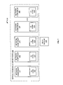
- FIG. 1 illustrates a communication system 100 in an embodiment of the invention.
- Communication system 100 includes an optical communication network 120 and a read system 130 .
- Optical communication network 120 is comprised of a plurality of network components 101 - 105 .
- Network components 101 - 105 may form part of optical communication network 120 and may be connected by multiple fiber optic cables that are not shown in FIG. 1 .
- a network component comprises any system or device configured to connect to a fiber optic cable and to facilitate the transport of optical signals over the fiber optic cable. Examples of a network component comprise optical transceivers, lasers, optical line cards, router cards, etc.
- Read system 130 comprises any system, device, or component configured to read an identification code from a network component 101 - 105 .
- Communication system 100 and optical communication network 120 may include other systems, devices, or components not shown for the sake of brevity.
- FIG. 2 is a flow chart illustrating a method 200 of verifying the identity of network connections in optical communication network 120 .
- Field technicians and network managers may want to verify the identity of network connections before field technicians connect/disconnect a fiber optic cable from a network component, such as to fix a problem with optical communication network 120 , to add wavelengths to optical communication network 120 , to debug optical communication network 120 , etc.
- a field technician may be instructed to connect a fiber optic cable to network component 103 in FIG. 1 to add a wavelength to optical communication network 120 .
- the following steps may take place.
- Step 202 of method 200 includes assigning each network component 101 - 105 an identification code 111 - 115 .
- the identification code identifies the network component and/or distinguishes the network component from other network components.
- Step 204 includes storing the identification code 111 - 115 for the network component 101 - 105 in the network component 101 - 105 , such as in a memory (see FIG. 1 ).
- Steps 202 and 204 may be preliminary steps that are used by manufacturers of network components 101 - 105 or other parties dealing with the service provider. Steps 202 - 204 may take place before the network components 101 - 105 are incorporated into optical communication network 120 .
- Step 206 includes positioning read system 130 proximate to network component 103 (i.e., the network component having the network connection of which the field technician wants to verify the identity).
- Step 206 may include positioning read system 130 proximate to any one of network components 101 - 105 , but network component 103 is used for illustration. Positioning in this instance may mean moving read system 130 , a peripheral device or antenna for read system 130 , etc, in the immediate area of network component 103 . Positioning in this instance may also mean positioning read system 130 so as to connect read system 130 to network component 103 optically or electrically in a wireless fashion.
- step 208 includes reading the identification code 113 stored on network component 103 using read system 130 .
- Reading in this instance may mean receiving a signal indicating the identification code 113 , transmitting a signal to receive another signal indicating the identification code 113 , transmitting a query to receive a response indicating the identification code 113 , etc.
- Step 210 includes verifying the identity of a network connection based on the identification code 113 read from network component 103 by read system 130 . Verifying the identity of a network connection means verifying a current network connection to network component 103 , or verifying a potential or future network connection to network component 103 .
- Step 212 includes indicating the results of the verification using read system 130 . For instance, indicating the results may mean sounding an alarm to indicate the results to the field technician, or displaying a message to the field technician indicating the results.
- the method 200 may further include authorizing the field technician to handle the network connection. For instance, the field technician may be authorized to connect a fiber optic cable to network component 103 . Method 200 may be repeated multiple times to handle more network connections.
- method 200 may help to ensure that a field technician is making the proper connections or disconnections within optical communication network 120 , and to reduce the chance of mistakes. If mistakes are reduced or eliminated, the services providers may be able to deliver new services to customers faster, and decrease service disruptions to the customers.
- FIG. 3 illustrates a communication system 300 in another embodiment of the invention.
- Communication system 300 is comprised of an optical communication network 310 and a hand-held reader 370 .
- Optical communication network 310 is a DWDM optical network comprised of a plurality of line cards 301 - 303 and a network management system 320 . Each line card 301 - 303 is able to communicate with network management system 320 .
- the line cards 301 - 303 may be secured in racks (not shown), such as in a hub of an optical communication network.
- Optical communication network 310 may include many other line cards, systems, devices, or components not shown for the sake of brevity.
- Line card 302 includes a processor 342 and a slot 352 configured to receive a network component.
- a transceiver (XCVR) 312 represents the network component that is inserted in slot 352 .
- Line card 302 may include a network component other than a transceiver, or may include multiple network components.
- transceiver 312 is able to communicate with processor 342 of line card 302 .
- Transceiver 312 includes a memory 316 , a wireless storage device 325 , and a port 322 .
- Line cards 301 and 303 may include similar configurations as line card 302 .
- Hand-held reader 370 may be used by a field technician for optical communication network 310 .
- Reader 370 includes a display 371 , a keypad 372 , an antenna 373 , and an antenna 374 .
- Reader 370 is configured to use antenna 373 to read an identification code and possibly other information from storage devices such as storage device 325 .
- Reader 370 is configured to use antenna 374 to communicate with other devices, such as with network management system 320 .
- Antenna 373 is most likely a short range antenna, such as a Radio Frequency Identification (RFID) antenna.
- Antenna 374 is most likely a longer-range antenna, such as an antenna for a cell phone.
- RFID Radio Frequency Identification
- FIG. 4 shows an isometric view of transceiver 312 in an embodiment of the invention.
- Transceiver 312 includes memory 316 , wireless storage device 325 , and port 322 .
- Storage device 325 comprises any device, component, or chip configured to store an identification code for transceiver 312 and communicate with hand-held reader 370 .
- Storage device 325 may be affixed on or in transceiver 312 at any desired location. In one embodiment, storage device 325 may be affixed in close proximity to a fiber optic connection point, such as port 322 on transceiver 312 .
- a storage device 325 is an RFID tag.
- Port 322 comprises any interface configured to receive or connect with a fiber optic cable.
- Memory 316 comprises any device, component, or chip configured to store an identification code for transceiver 312 and communicate with processor 342 of line card 302 (see FIG. 3 ). Examples of memory 316 include an Electrical Programmable Read-Only Memory (EPROM) and an Erasable EPROM (EEPROM).
- EPROM Electrical Programmable Read-Only Memory
- EEPROM Erasable EPROM
- Transceiver 312 may comprise a Small Form Factor (SFF) transceiver.
- SFF Small Form Factor
- FTRX-1411-3 Optical Transceiver from Finisar Corporation.
- XP3-SA2 Optical Transceiver from JDS Uniphase.
- each transceiver 311 - 313 is assigned an identification code.
- Each identification code is a different or globally unique identification code, number, address, etc., that identifies the transceiver and/or distinguishes the transceiver from other network components.
- the identification code may be a 32-bit address that resembles an Ethernet address.
- a manufacturer of the transceiver 331 - 313 may assign the identification codes.
- a network administrator may assign the identification codes or the network management system 320 may automatically assign the identification codes.
- the transceivers 311 - 313 store their identification code on storage devices 324 - 326 , respectively.
- Storage devices 324 - 326 may comprise RFID tags, or some other device configured to store an identification code and provide a wireless signal indicating the identification code.
- the transceivers 311 - 313 may also store their identification code in memory 315 - 317 , respectively.
- the identification codes stored in memory 315 - 317 may be used to register the identification codes and the corresponding transceivers 311 - 313 with network management system 320 . For instance, when transceiver 312 is initially plugged into slot 352 of line card 302 , transceiver 312 may forward its identification code stored in memory 316 to processor 342 . Processor 342 , in response to receiving the identification code, registers the identification code and transceiver 312 with network management system 320 .
- optical communication network 310 Assume that the network administrator wishes to add a wavelength to optical communication network 310 . To add a wavelength, a field technician will have to connect or disconnect fiber optic cables to transceivers 311 - 313 and other transceivers not shown.
- An actual optical communication network will include many more transceivers and line cards connected by multiple fiber optic cables than that shown in FIG. 3 . The number of transceivers and fiber optic cables may make connections and disconnections of fiber optic cables a difficult task.
- the field technician may load a work order onto reader 370 .
- the work order may include a list of instructions for the field technician to perform to provision the new wavelength.
- the network management system 320 may automatically generate the work order or network administrators may manually generate the work order.
- the field technician may load the work order onto reader 370 by connecting reader 370 to network management system 320 or another computer, either directly or remotely through antenna 374 while the field technician is in the field. Once connected to network management system 320 , reader 370 may load the proper work order based on a work number.
- the field technician may operate reader 370 to display a list of instructions to perform and/or a connection diagram from the work order.
- the work order may first instruct the field technician to connect a fiber optic cable to the transceiver in the second line card in the first rack (i.e., transceiver 312 in line card 302 ).
- the field technician identifies the transceiver that he/she thinks is the correct transceiver with which to connection the fiber optic cable.
- the field technician positions antenna 373 of reader 370 proximate to transceiver 312 .
- the field technician positions antenna 373 of reader 370 proximate to storage device 325 of transceiver 312 .
- reader 370 reads the identification code from storage device 325 of transceiver 312 .
- Antenna 373 may read the identification code by transmitting a radio frequency signal to storage device 325 , and receiving a radio frequency signal from storage device 325 indicating the identification code.
- antenna 373 is configured to communicate with only one storage device 325 even if two or more storage devices 325 are within a small area. For instance, if storage device 325 is an RFID tag, then the reception/transmission distance of the RFID tag may be limited to 2 cm or less to keep neighboring RFID tags from interfering with one another. To prevent false identification, antenna 373 reads only one storage device 325 when placed proximate to the storage device 325 . One way to avoid false identifications is to instruct the field technician to insert antenna 373 partially or completely into port 322 of transceiver 312 . If storage device 325 is located very close to port 322 , then antenna 373 will be proximate to storage device 325 when the antenna 373 is inserted into port 322 of transceiver 312 .
- reader 370 After reading the identification code from transceiver 312 , reader 370 compares the identification code read from transceiver 312 with a known identification code for the transceiver needed for the proper network connection. Reader 370 knows the identification code of the transceiver needed for the proper network connection based on information in the work order. If the identification codes match, then reader 370 indicates the match for the proper network connection with an audible indicator such as a beep, or a visual indicator such as a message on display 371 . Reader 370 may also authorize a connection or disconnection of a fiber optic cable to transceiver 312 , or authorize the field technician to otherwise handle transceiver 312 , based on the identification code read from transceiver 312 matching the known identification code. The field technician thus knows that the transceiver 312 is the proper transceiver for which to plug a fiber optic cable. Reader 370 may also indicate transceiver 312 and the proper network connection on a connection diagram for the convenience of the field technician.
- transceiver 312 is not the transceiver needed for the proper network connection. The field technician then needs to find the transceiver needed for the proper network connection.
- the comparison of identification codes may take place in the network management system 320 .
- reader 370 may read the identification code from storage device 325 of transceiver 312 .
- reader 370 forwards the identification code read from transceiver 312 to network management system 320 .
- Network management system 320 knows the identification code of the transceiver needed for the proper network connection based on information in the work order.
- Network management system 320 compares the identification code read from transceiver 312 to the known identification code for the transceiver needed for the proper network connection. If the identification codes match, then network management system 320 forwards a message to reader 370 indicating that transceiver 312 is the transceiver needed for the proper network connection.
- reader 370 Responsive to the message, reader 370 provides an audible indicator, visual indicator, etc. If the identification codes do not match, then network management system 320 forwards a message to reader 370 indicating that transceiver 312 is not the transceiver needed for the proper network connection. Responsive to the message, reader 370 provides an audible indicator, a visual indicator, etc.
- Line cards 301 - 303 or other network components in FIG. 3 may also be assigned identification codes.
- the identification codes may be stored on a storage device, such as an RFID tag. Field technicians may read the identification codes any time the identity of a network connection needs to be verified.
- a field technician may quickly verify the identity of the network connection by reading the identification code on the network component. This helps ensure that a field technician is making the proper connections or disconnections within an optical communication network, and reduces the chance of mistakes.
- the identification code on a network component may be used to determine the identity of the network component for other reasons. For instance, if a new network component is needed to replace an existing network component, then the identification code of the existing network component may be read to verify the identity of the existing network component. Once the identity of the existing network component is verified, the existing network component may be replaced with the new network component.
Landscapes
- Physics & Mathematics (AREA)
- Electromagnetism (AREA)
- Engineering & Computer Science (AREA)
- Computer Networks & Wireless Communication (AREA)
- Signal Processing (AREA)
- Optical Communication System (AREA)
- Data Exchanges In Wide-Area Networks (AREA)
Abstract
Description
Claims (24)
Priority Applications (1)
| Application Number | Priority Date | Filing Date | Title |
|---|---|---|---|
| US10/838,798 US7623784B1 (en) | 2004-05-04 | 2004-05-04 | Network connection verification in optical communication networks |
Applications Claiming Priority (1)
| Application Number | Priority Date | Filing Date | Title |
|---|---|---|---|
| US10/838,798 US7623784B1 (en) | 2004-05-04 | 2004-05-04 | Network connection verification in optical communication networks |
Publications (1)
| Publication Number | Publication Date |
|---|---|
| US7623784B1 true US7623784B1 (en) | 2009-11-24 |
Family
ID=41327880
Family Applications (1)
| Application Number | Title | Priority Date | Filing Date |
|---|---|---|---|
| US10/838,798 Active 2026-09-23 US7623784B1 (en) | 2004-05-04 | 2004-05-04 | Network connection verification in optical communication networks |
Country Status (1)
| Country | Link |
|---|---|
| US (1) | US7623784B1 (en) |
Cited By (16)
| Publication number | Priority date | Publication date | Assignee | Title |
|---|---|---|---|---|
| US20080031620A1 (en) * | 2006-08-04 | 2008-02-07 | Emcore Corporation | Wireless monitoring of optoelectronic modules and network components |
| US20080166131A1 (en) * | 2007-01-05 | 2008-07-10 | Hudgins Clay E | Parametric monitoring of optoelectronic modules on host system |
| US20110193690A1 (en) * | 2007-09-03 | 2011-08-11 | Froehlich Paul | Method for identification of components in an electrical low-voltage switchgear assembly |
| CN102801462A (en) * | 2011-05-23 | 2012-11-28 | 中兴通讯股份有限公司 | Method and device for detecting optical fiber connection |
| US20150053758A1 (en) * | 2013-08-26 | 2015-02-26 | Fu Tai Hua Industry (Shenzhen) Co., Ltd. | Fiber management system and method thereof |
| US20150120927A1 (en) * | 2013-10-24 | 2015-04-30 | Ciena Corporation | Network based onsite support |
| CN105243416A (en) * | 2015-09-15 | 2016-01-13 | 国网北京市电力公司 | Method and device for finding buried cable, and intelligent electronic label of buried cable |
| CN105245282A (en) * | 2015-11-03 | 2016-01-13 | 黄迪 | Intelligent optical fiber management system and testing method thereof |
| US9479219B1 (en) | 2012-09-24 | 2016-10-25 | Google Inc. | Validating a connection to an optical circuit switch |
| CN102801462B (en) * | 2011-05-23 | 2016-11-30 | 南京中兴新软件有限责任公司 | The detection method of optical fiber connection and device |
| US9749039B1 (en) * | 2013-06-10 | 2017-08-29 | Amazon Technologies, Inc. | Portable connection diagnostic device |
| US10097443B2 (en) | 2015-12-16 | 2018-10-09 | Fluke Corporation | System and method for secure communications between a computer test tool and a cloud-based server |
| US10361945B2 (en) * | 2015-10-08 | 2019-07-23 | Fluke Corporation | System and method to reconcile cabling test results with cabling test configurations |
| US10367713B2 (en) | 2015-10-15 | 2019-07-30 | Fluke Corporation | Cloud based system and method for managing testing configurations for cable test devices |
| US20200059710A1 (en) * | 2018-08-20 | 2020-02-20 | Quanta Computer Inc. | Optical cable identification tool |
| JP2020527752A (en) * | 2017-07-19 | 2020-09-10 | ファイバー・マウンテン・インコーポレイテッド | Fiber connector assembly |
Citations (10)
| Publication number | Priority date | Publication date | Assignee | Title |
|---|---|---|---|---|
| US20020176131A1 (en) * | 2001-02-28 | 2002-11-28 | Walters David H. | Protection switching for an optical network, and methods and apparatus therefor |
| US20030021580A1 (en) * | 2001-07-18 | 2003-01-30 | Photoris, Inc. | Method and apparatus for coupling terminal equipment to a node in an optical communications network |
| US20030061393A1 (en) * | 2001-09-21 | 2003-03-27 | Frank Steegmans | System and method for improving the management of information in networks by disposing machine accessible information tags along the interconnection means |
| US20030180042A1 (en) * | 2002-03-20 | 2003-09-25 | Nelles David Edward | Method for visualization of optical network topology |
| US6694455B1 (en) * | 2000-06-16 | 2004-02-17 | Ciena Corporation | Communications network and method performing distributed processing of fault and alarm objects |
| US6704407B1 (en) * | 1998-12-23 | 2004-03-09 | Nokia Networks Oy | Interface for digital telecommunications system |
| US6810496B1 (en) * | 2001-11-07 | 2004-10-26 | Ciena Corporation | System and method for troubleshooting a network |
| US6917759B2 (en) * | 2002-01-31 | 2005-07-12 | Nortel Networks Limited | Shared mesh signaling algorithm and apparatus |
| US20060220838A1 (en) * | 2003-04-03 | 2006-10-05 | Peter Wakim | Network serving device, portable electronic device, system and methods for mediating networked services |
| US20070043849A1 (en) * | 2003-09-05 | 2007-02-22 | David Lill | Field data collection and processing system, such as for electric, gas, and water utility data |
-
2004
- 2004-05-04 US US10/838,798 patent/US7623784B1/en active Active
Patent Citations (10)
| Publication number | Priority date | Publication date | Assignee | Title |
|---|---|---|---|---|
| US6704407B1 (en) * | 1998-12-23 | 2004-03-09 | Nokia Networks Oy | Interface for digital telecommunications system |
| US6694455B1 (en) * | 2000-06-16 | 2004-02-17 | Ciena Corporation | Communications network and method performing distributed processing of fault and alarm objects |
| US20020176131A1 (en) * | 2001-02-28 | 2002-11-28 | Walters David H. | Protection switching for an optical network, and methods and apparatus therefor |
| US20030021580A1 (en) * | 2001-07-18 | 2003-01-30 | Photoris, Inc. | Method and apparatus for coupling terminal equipment to a node in an optical communications network |
| US20030061393A1 (en) * | 2001-09-21 | 2003-03-27 | Frank Steegmans | System and method for improving the management of information in networks by disposing machine accessible information tags along the interconnection means |
| US6810496B1 (en) * | 2001-11-07 | 2004-10-26 | Ciena Corporation | System and method for troubleshooting a network |
| US6917759B2 (en) * | 2002-01-31 | 2005-07-12 | Nortel Networks Limited | Shared mesh signaling algorithm and apparatus |
| US20030180042A1 (en) * | 2002-03-20 | 2003-09-25 | Nelles David Edward | Method for visualization of optical network topology |
| US20060220838A1 (en) * | 2003-04-03 | 2006-10-05 | Peter Wakim | Network serving device, portable electronic device, system and methods for mediating networked services |
| US20070043849A1 (en) * | 2003-09-05 | 2007-02-22 | David Lill | Field data collection and processing system, such as for electric, gas, and water utility data |
Cited By (22)
| Publication number | Priority date | Publication date | Assignee | Title |
|---|---|---|---|---|
| US7856185B2 (en) * | 2006-08-04 | 2010-12-21 | Emcore Corporation | Wireless monitoring of optoelectronic modules and network components |
| US20080031620A1 (en) * | 2006-08-04 | 2008-02-07 | Emcore Corporation | Wireless monitoring of optoelectronic modules and network components |
| US20080166131A1 (en) * | 2007-01-05 | 2008-07-10 | Hudgins Clay E | Parametric monitoring of optoelectronic modules on host system |
| US7853150B2 (en) * | 2007-01-05 | 2010-12-14 | Emcore Corporation | Identification and authorization of optoelectronic modules by host system |
| US8917164B2 (en) * | 2007-09-03 | 2014-12-23 | Siemens Aktiengesellschaft | Method for identification of components in an electrical low-voltage switchgear assembly |
| US20110193690A1 (en) * | 2007-09-03 | 2011-08-11 | Froehlich Paul | Method for identification of components in an electrical low-voltage switchgear assembly |
| CN102801462B (en) * | 2011-05-23 | 2016-11-30 | 南京中兴新软件有限责任公司 | The detection method of optical fiber connection and device |
| CN102801462A (en) * | 2011-05-23 | 2012-11-28 | 中兴通讯股份有限公司 | Method and device for detecting optical fiber connection |
| US9479219B1 (en) | 2012-09-24 | 2016-10-25 | Google Inc. | Validating a connection to an optical circuit switch |
| US9749039B1 (en) * | 2013-06-10 | 2017-08-29 | Amazon Technologies, Inc. | Portable connection diagnostic device |
| US20150053758A1 (en) * | 2013-08-26 | 2015-02-26 | Fu Tai Hua Industry (Shenzhen) Co., Ltd. | Fiber management system and method thereof |
| US20150120927A1 (en) * | 2013-10-24 | 2015-04-30 | Ciena Corporation | Network based onsite support |
| US9729265B2 (en) * | 2013-10-24 | 2017-08-08 | Ciena Corporation | Network based onsite support |
| CN105243416A (en) * | 2015-09-15 | 2016-01-13 | 国网北京市电力公司 | Method and device for finding buried cable, and intelligent electronic label of buried cable |
| US10361945B2 (en) * | 2015-10-08 | 2019-07-23 | Fluke Corporation | System and method to reconcile cabling test results with cabling test configurations |
| US10367713B2 (en) | 2015-10-15 | 2019-07-30 | Fluke Corporation | Cloud based system and method for managing testing configurations for cable test devices |
| CN105245282A (en) * | 2015-11-03 | 2016-01-13 | 黄迪 | Intelligent optical fiber management system and testing method thereof |
| US10097443B2 (en) | 2015-12-16 | 2018-10-09 | Fluke Corporation | System and method for secure communications between a computer test tool and a cloud-based server |
| JP2020527752A (en) * | 2017-07-19 | 2020-09-10 | ファイバー・マウンテン・インコーポレイテッド | Fiber connector assembly |
| US11650380B2 (en) * | 2017-07-19 | 2023-05-16 | Green Lambda Corporation | Fiber connector assembly |
| US20200059710A1 (en) * | 2018-08-20 | 2020-02-20 | Quanta Computer Inc. | Optical cable identification tool |
| US10694269B2 (en) * | 2018-08-20 | 2020-06-23 | Quanta Computer Inc. | Optical cable identification tool |
Similar Documents
| Publication | Publication Date | Title |
|---|---|---|
| US9064022B2 (en) | Component identification and tracking system for telecommunication networks | |
| US7623784B1 (en) | Network connection verification in optical communication networks | |
| US8210755B2 (en) | Identifiable fiber optics | |
| US12386126B2 (en) | Connectivity appliance | |
| US8731405B2 (en) | RFID-based systems and methods for collecting telecommunications network information | |
| CN104539640B (en) | Managed connectivity devices, systems and methods | |
| EP2098095B1 (en) | Rfid systems and methods for optical fiber network deployment and maintenance | |
| US9130318B2 (en) | Localized reading of RFID tags located on multiple sides of a port from a single side using RFID coupling circuit and portable RFID reader | |
| US20100079248A1 (en) | Optical fiber connector assembly with wire-based RFID antenna | |
| US11747876B2 (en) | Systems and methods for network port occupancy state change monitoring using low energy wireless communications | |
| US20110111750A1 (en) | Method for the diagnostic testing of a mobile telephone terminal including contactless applications | |
| US20170163573A1 (en) | Systems and methods for detecting component rotation within a communication assembly | |
| US10462540B2 (en) | Intelligent system for interconnecting data networking equipment | |
| KR20230069023A (en) | Passive optical couplers having passive optical activity indicators and methods of operating the same | |
| US12335259B2 (en) | Systems and methods for automated configuration of communications equipment | |
| US10374920B2 (en) | Communication media and methods for providing indication of signal power to a network entity | |
| KR20230069024A (en) | Systems and methods for mapping optical connections in a fiber distribution hub of a passive optical network | |
| KR102139973B1 (en) | Administration module of optical cable and method for operating using the same | |
| AU2012255814A1 (en) | Component identification and tracking systems for telecommunication networks | |
| CN106162384A (en) | The roaming authentication method of a kind of optical network access equipment and relevant device |
Legal Events
| Date | Code | Title | Description |
|---|---|---|---|
| AS | Assignment |
Owner name: SPRINT COMMUNICATIONS COMPANY, L.P., KANSAS Free format text: ASSIGNMENT OF ASSIGNORS INTEREST;ASSIGNORS:PAN, JAMES J.;WHITE, IAN M.;REEL/FRAME:015304/0927 Effective date: 20040426 |
|
| STCF | Information on status: patent grant |
Free format text: PATENTED CASE |
|
| CC | Certificate of correction | ||
| FPAY | Fee payment |
Year of fee payment: 4 |
|
| AS | Assignment |
Owner name: DEUTSCHE BANK TRUST COMPANY AMERICAS, NEW YORK Free format text: GRANT OF FIRST PRIORITY AND JUNIOR PRIORITY SECURITY INTEREST IN PATENT RIGHTS;ASSIGNOR:SPRINT COMMUNICATIONS COMPANY L.P.;REEL/FRAME:041895/0210 Effective date: 20170203 |
|
| FPAY | Fee payment |
Year of fee payment: 8 |
|
| AS | Assignment |
Owner name: SPRINT COMMUNICATIONS COMPANY L.P., KANSAS Free format text: TERMINATION AND RELEASE OF FIRST PRIORITY AND JUNIOR PRIORITY SECURITY INTEREST IN PATENT RIGHTS;ASSIGNOR:DEUTSCHE BANK TRUST COMPANY AMERICAS;REEL/FRAME:052969/0475 Effective date: 20200401 Owner name: DEUTSCHE BANK TRUST COMPANY AMERICAS, NEW YORK Free format text: SECURITY AGREEMENT;ASSIGNORS:T-MOBILE USA, INC.;ISBV LLC;T-MOBILE CENTRAL LLC;AND OTHERS;REEL/FRAME:053182/0001 Effective date: 20200401 |
|
| AS | Assignment |
Owner name: T-MOBILE INNOVATIONS LLC, KANSAS Free format text: ASSIGNMENT OF ASSIGNORS INTEREST;ASSIGNOR:SPRINT COMMUNICATIONS COMPANY L.P.;REEL/FRAME:055604/0001 Effective date: 20210303 Owner name: T-MOBILE INNOVATIONS LLC, KANSAS Free format text: ASSIGNMENT OF ASSIGNOR'S INTEREST;ASSIGNOR:SPRINT COMMUNICATIONS COMPANY L.P.;REEL/FRAME:055604/0001 Effective date: 20210303 |
|
| MAFP | Maintenance fee payment |
Free format text: PAYMENT OF MAINTENANCE FEE, 12TH YEAR, LARGE ENTITY (ORIGINAL EVENT CODE: M1553); ENTITY STATUS OF PATENT OWNER: LARGE ENTITY Year of fee payment: 12 |
|
| AS | Assignment |
Owner name: SPRINT SPECTRUM LLC, KANSAS Free format text: RELEASE BY SECURED PARTY;ASSIGNOR:DEUTSCHE BANK TRUST COMPANY AMERICAS;REEL/FRAME:062595/0001 Effective date: 20220822 Owner name: SPRINT INTERNATIONAL INCORPORATED, KANSAS Free format text: RELEASE BY SECURED PARTY;ASSIGNOR:DEUTSCHE BANK TRUST COMPANY AMERICAS;REEL/FRAME:062595/0001 Effective date: 20220822 Owner name: SPRINT COMMUNICATIONS COMPANY L.P., KANSAS Free format text: RELEASE BY SECURED PARTY;ASSIGNOR:DEUTSCHE BANK TRUST COMPANY AMERICAS;REEL/FRAME:062595/0001 Effective date: 20220822 Owner name: SPRINTCOM LLC, KANSAS Free format text: RELEASE BY SECURED PARTY;ASSIGNOR:DEUTSCHE BANK TRUST COMPANY AMERICAS;REEL/FRAME:062595/0001 Effective date: 20220822 Owner name: CLEARWIRE IP HOLDINGS LLC, KANSAS Free format text: RELEASE BY SECURED PARTY;ASSIGNOR:DEUTSCHE BANK TRUST COMPANY AMERICAS;REEL/FRAME:062595/0001 Effective date: 20220822 Owner name: CLEARWIRE COMMUNICATIONS LLC, KANSAS Free format text: RELEASE BY SECURED PARTY;ASSIGNOR:DEUTSCHE BANK TRUST COMPANY AMERICAS;REEL/FRAME:062595/0001 Effective date: 20220822 Owner name: BOOST WORLDWIDE, LLC, KANSAS Free format text: RELEASE BY SECURED PARTY;ASSIGNOR:DEUTSCHE BANK TRUST COMPANY AMERICAS;REEL/FRAME:062595/0001 Effective date: 20220822 Owner name: ASSURANCE WIRELESS USA, L.P., KANSAS Free format text: RELEASE BY SECURED PARTY;ASSIGNOR:DEUTSCHE BANK TRUST COMPANY AMERICAS;REEL/FRAME:062595/0001 Effective date: 20220822 Owner name: T-MOBILE USA, INC., WASHINGTON Free format text: RELEASE BY SECURED PARTY;ASSIGNOR:DEUTSCHE BANK TRUST COMPANY AMERICAS;REEL/FRAME:062595/0001 Effective date: 20220822 Owner name: T-MOBILE CENTRAL LLC, WASHINGTON Free format text: RELEASE BY SECURED PARTY;ASSIGNOR:DEUTSCHE BANK TRUST COMPANY AMERICAS;REEL/FRAME:062595/0001 Effective date: 20220822 Owner name: PUSHSPRING, LLC, WASHINGTON Free format text: RELEASE BY SECURED PARTY;ASSIGNOR:DEUTSCHE BANK TRUST COMPANY AMERICAS;REEL/FRAME:062595/0001 Effective date: 20220822 Owner name: LAYER3 TV, LLC, WASHINGTON Free format text: RELEASE BY SECURED PARTY;ASSIGNOR:DEUTSCHE BANK TRUST COMPANY AMERICAS;REEL/FRAME:062595/0001 Effective date: 20220822 Owner name: IBSV LLC, WASHINGTON Free format text: RELEASE BY SECURED PARTY;ASSIGNOR:DEUTSCHE BANK TRUST COMPANY AMERICAS;REEL/FRAME:062595/0001 Effective date: 20220822 Owner name: IBSV LLC, WASHINGTON Free format text: RELEASE OF SECURITY INTEREST;ASSIGNOR:DEUTSCHE BANK TRUST COMPANY AMERICAS;REEL/FRAME:062595/0001 Effective date: 20220822 Owner name: LAYER3 TV, LLC, WASHINGTON Free format text: RELEASE OF SECURITY INTEREST;ASSIGNOR:DEUTSCHE BANK TRUST COMPANY AMERICAS;REEL/FRAME:062595/0001 Effective date: 20220822 Owner name: PUSHSPRING, LLC, WASHINGTON Free format text: RELEASE OF SECURITY INTEREST;ASSIGNOR:DEUTSCHE BANK TRUST COMPANY AMERICAS;REEL/FRAME:062595/0001 Effective date: 20220822 Owner name: T-MOBILE CENTRAL LLC, WASHINGTON Free format text: RELEASE OF SECURITY INTEREST;ASSIGNOR:DEUTSCHE BANK TRUST COMPANY AMERICAS;REEL/FRAME:062595/0001 Effective date: 20220822 Owner name: T-MOBILE USA, INC., WASHINGTON Free format text: RELEASE OF SECURITY INTEREST;ASSIGNOR:DEUTSCHE BANK TRUST COMPANY AMERICAS;REEL/FRAME:062595/0001 Effective date: 20220822 Owner name: ASSURANCE WIRELESS USA, L.P., KANSAS Free format text: RELEASE OF SECURITY INTEREST;ASSIGNOR:DEUTSCHE BANK TRUST COMPANY AMERICAS;REEL/FRAME:062595/0001 Effective date: 20220822 Owner name: BOOST WORLDWIDE, LLC, KANSAS Free format text: RELEASE OF SECURITY INTEREST;ASSIGNOR:DEUTSCHE BANK TRUST COMPANY AMERICAS;REEL/FRAME:062595/0001 Effective date: 20220822 Owner name: CLEARWIRE COMMUNICATIONS LLC, KANSAS Free format text: RELEASE OF SECURITY INTEREST;ASSIGNOR:DEUTSCHE BANK TRUST COMPANY AMERICAS;REEL/FRAME:062595/0001 Effective date: 20220822 Owner name: CLEARWIRE IP HOLDINGS LLC, KANSAS Free format text: RELEASE OF SECURITY INTEREST;ASSIGNOR:DEUTSCHE BANK TRUST COMPANY AMERICAS;REEL/FRAME:062595/0001 Effective date: 20220822 Owner name: SPRINTCOM LLC, KANSAS Free format text: RELEASE OF SECURITY INTEREST;ASSIGNOR:DEUTSCHE BANK TRUST COMPANY AMERICAS;REEL/FRAME:062595/0001 Effective date: 20220822 Owner name: SPRINT COMMUNICATIONS COMPANY L.P., KANSAS Free format text: RELEASE OF SECURITY INTEREST;ASSIGNOR:DEUTSCHE BANK TRUST COMPANY AMERICAS;REEL/FRAME:062595/0001 Effective date: 20220822 Owner name: SPRINT INTERNATIONAL INCORPORATED, KANSAS Free format text: RELEASE OF SECURITY INTEREST;ASSIGNOR:DEUTSCHE BANK TRUST COMPANY AMERICAS;REEL/FRAME:062595/0001 Effective date: 20220822 Owner name: SPRINT SPECTRUM LLC, KANSAS Free format text: RELEASE OF SECURITY INTEREST;ASSIGNOR:DEUTSCHE BANK TRUST COMPANY AMERICAS;REEL/FRAME:062595/0001 Effective date: 20220822 |