US7614325B2 - Tool protection apparatus - Google Patents
Tool protection apparatus Download PDFInfo
- Publication number
- US7614325B2 US7614325B2 US11/980,810 US98081007A US7614325B2 US 7614325 B2 US7614325 B2 US 7614325B2 US 98081007 A US98081007 A US 98081007A US 7614325 B2 US7614325 B2 US 7614325B2
- Authority
- US
- United States
- Prior art keywords
- handle
- protecting cover
- disposed
- protection apparatus
- tool
- Prior art date
- Legal status (The legal status is an assumption and is not a legal conclusion. Google has not performed a legal analysis and makes no representation as to the accuracy of the status listed.)
- Expired - Fee Related, expires
Links
Images


Classifications
-
- B—PERFORMING OPERATIONS; TRANSPORTING
- B25—HAND TOOLS; PORTABLE POWER-DRIVEN TOOLS; MANIPULATORS
- B25B—TOOLS OR BENCH DEVICES NOT OTHERWISE PROVIDED FOR, FOR FASTENING, CONNECTING, DISENGAGING, OR HOLDING
- B25B15/00—Screwdrivers
-
- B—PERFORMING OPERATIONS; TRANSPORTING
- B25—HAND TOOLS; PORTABLE POWER-DRIVEN TOOLS; MANIPULATORS
- B25G—HANDLES FOR HAND IMPLEMENTS
- B25G1/00—Handle constructions
Definitions
- the present invention relates to a tool protection apparatus that comes with a simple and easy operation and a high safety.
- a tool head of the hand tool 4 has a sharp distal edge to cope with its operating effect.
- the sharp edge of the hand tool 4 can give a good operating effect, yet it is dangerous to carry a sharp tool, particularly when the hand tool 4 drops by accident, it may jeopardize the safety of users, and thus the present invention intends to improve the safety issue of the aforementioned hand tool.
- the present invention provides a tool protection apparatus, comprising:
- a protecting cover pivotally coupled to an end of the handle, and being substantially in a U-shape and hollow on both lateral sides;
- each of the pivotal connection portions comprising a latch hole and a circular hole
- FIG. 1 is a perspective view of the present invention
- FIG. 2 is a schematic view of operating and using the present invention
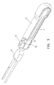
- FIG. 3 is a perspective view of operating and using the present invention.
- FIG. 4 is a schematic view of a second preferred embodiment of the present invention.
- FIG. 5 is a schematic view of a conventional hand tool.
- FIGS. 1 to 3 for a structure of a tool protection apparatus in accordance with a preferred embodiment of the present invention, the embodiment is used for illustrating the invention only, but not intended for limiting the scope of the present invention.
- a protecting cover 2 pivotally coupled to an end of the handle 1 , and the protecting cover 2 being substantially in a U-shape and hollow on both lateral sides, and in this embodiment, wherein the protecting cover 2 is integrally formed (by injection molding);
- each of the pivotal connection portions 21 comprising a latch hole 211 and a circular hole 212 ;
- the present invention provides a safer way of carrying a tool by pivotally turning the protecting cover 2 to a position of a tool head 3 , so as to cover the sharp distal edge of the tool head 3 .
- a user pivotally turns the protecting cover 2 to the handle 1 to expose the tool piece 3 for its use, whenever the user wants to use the tool.
- the operation procedure includes a step of pushing the protecting cover 2 towards the handle 1 , wherein the pivotal connection portion 21 includes a latch hole 211 and a circular hole 212 , and thus the external diameter of the latch hole 211 is approximately equal to the external diameter of the protruding pillar 11 to provide a latching effect, and the external diameter of the circular hole 212 is greater than the external diameter of the protruding pillar 11 of the handle 1 , such that when the protruding pillar 11 is installed into the circular hole 212 , the protecting cover 2 slides away from the latch of the latch hole 211 for a pivotal turn, and the protecting cover 2 is pushed towards the handle 1 by sliding the protruding pillar 11 away from the latch hole 211 , and entering into the circular hole 212 to facilitate a pivotal turn.
- the protecting cover 2 After the protecting cover 2 is turned pivotally to overlap with the handle 1 , the stop portion 12 of the handle 1 is limited by the limit position slot 22 of the protecting cover 2 , and thus the protecting cover 2 can no longer be turned pivotally. Now, the protecting cover 2 is pushed further towards the tool head 3 , so that the protruding pillar 11 enters into the position of the latch hole 211 from the position of the circular hole 212 to achieve the effect of positioning the protecting cover 2 . If it is necessary to store the tool after its use, the operation procedure is reversed. The protecting cover 2 is positioned to cover the position of the tool head 3 , so as to facilitate users to carry the tool safely.
- the tool protection apparatus uses a stop portion 12 to press against the protecting cover 2 proximate to an end of the handle 1 , so as to provide a safe tool protection apparatus.
- the present invention is definitely a safe, easy-to-use and convenient tool protection apparatus.
Landscapes
- Engineering & Computer Science (AREA)
- Mechanical Engineering (AREA)
- Auxiliary Devices For Machine Tools (AREA)
- Workshop Equipment, Work Benches, Supports, Or Storage Means (AREA)
Abstract
A tool protection apparatus includes a handle; a protecting cover pivotally coupled to an end of the handle, and substantially U-shaped and hollow on both lateral sides; two pivotal connection portions, each disposed separately on top and bottom surfaces of an intersection of the handle and the protecting cover, and including a latch hole and a circular hole; two protruding pillars, each disposed separately on top and bottom surfaces of an intersection of the handle and the protecting cover, and passing through each circular hole; two limit position slots, each disposed on the protecting cover and at a position proximate to the pivotal connection portion; two stop portions, each disposed on the handle and at a position proximate to the protruding pillar, and the stop portion can be latched precisely into limit position slot, such that the present invention is a safe and easy-to operate tool protection apparatus.
Description
1. Field of the Invention
The present invention relates to a tool protection apparatus that comes with a simple and easy operation and a high safety.
2. Description of the Related Art
Referring to FIG. 5 for a general prior art hand tool 3, a tool head of the hand tool 4 has a sharp distal edge to cope with its operating effect. Although the sharp edge of the hand tool 4 can give a good operating effect, yet it is dangerous to carry a sharp tool, particularly when the hand tool 4 drops by accident, it may jeopardize the safety of users, and thus the present invention intends to improve the safety issue of the aforementioned hand tool.
It is a primary objective of the present invention to provide a tool protection apparatus that comes with a simple operation and a high safety to overcome the shortcomings of the prior art.
To achieve the foregoing objective, the present invention provides a tool protection apparatus, comprising:
a handle;
a protecting cover, pivotally coupled to an end of the handle, and being substantially in a U-shape and hollow on both lateral sides;
two pivotal connection portions, each disposed separately on top and bottom surfaces of an intersection of the handle and the protecting cover, and each of the pivotal connection portions comprising a latch hole and a circular hole;
two protruding pillars, each disposed separately on top and bottom surfaces of an intersection of the handle and the protecting cover, and each of the protruding pillars passing through each circular hole;
two limit position slots, each disposed on the protecting cover and at a position proximate to the pivotal connection portion; and
two stop portions, each disposed on the handle and at a position proximate to the protruding pillar, and the stop portion being latched precisely into the limit position slot.
Referring to FIGS. 1 to 3 for a structure of a tool protection apparatus in accordance with a preferred embodiment of the present invention, the embodiment is used for illustrating the invention only, but not intended for limiting the scope of the present invention.
The tool protection apparatus in accordance with a preferred embodiment of the present invention comprises:
a handle 1;
a protecting cover 2, pivotally coupled to an end of the handle 1, and the protecting cover 2 being substantially in a U-shape and hollow on both lateral sides, and in this embodiment, wherein the protecting cover 2 is integrally formed (by injection molding);
two pivotal connection portions 21, each disposed separately on top and bottom surfaces of an intersection of the handle 1 and the protecting cover 2, and each of the pivotal connection portions 21 comprising a latch hole 211 and a circular hole 212;
two protruding pillars 11, each disposed separately on top and bottom surfaces of an intersection of the handle 1 and the protecting cover 2, and each of the protruding pillars 11 passing through each circular hole 212;
two limit position slots 22, each disposed on the protecting cover 2 and at a position proximate to the pivotal connection portion 21; and
two stop portions 12, each disposed on the handle 1 and at a position proximate to the protruding pillar 11, and the stop portion 12 being latched precisely into the limit position slot 22.
In FIG. 1 , the present invention provides a safer way of carrying a tool by pivotally turning the protecting cover 2 to a position of a tool head 3, so as to cover the sharp distal edge of the tool head 3.
In FIGS. 2 and 3 , a user pivotally turns the protecting cover 2 to the handle 1 to expose the tool piece 3 for its use, whenever the user wants to use the tool. The operation procedure includes a step of pushing the protecting cover 2 towards the handle 1, wherein the pivotal connection portion 21 includes a latch hole 211 and a circular hole 212, and thus the external diameter of the latch hole 211 is approximately equal to the external diameter of the protruding pillar 11 to provide a latching effect, and the external diameter of the circular hole 212 is greater than the external diameter of the protruding pillar 11 of the handle 1, such that when the protruding pillar 11 is installed into the circular hole 212, the protecting cover 2 slides away from the latch of the latch hole 211 for a pivotal turn, and the protecting cover 2 is pushed towards the handle 1 by sliding the protruding pillar 11 away from the latch hole 211, and entering into the circular hole 212 to facilitate a pivotal turn. After the protecting cover 2 is turned pivotally to overlap with the handle 1, the stop portion 12 of the handle 1 is limited by the limit position slot 22 of the protecting cover 2, and thus the protecting cover 2 can no longer be turned pivotally. Now, the protecting cover 2 is pushed further towards the tool head 3, so that the protruding pillar 11 enters into the position of the latch hole 211 from the position of the circular hole 212 to achieve the effect of positioning the protecting cover 2. If it is necessary to store the tool after its use, the operation procedure is reversed. The protecting cover 2 is positioned to cover the position of the tool head 3, so as to facilitate users to carry the tool safely.
Referring to FIG. 4 for a second preferred embodiment of the present invention, the tool protection apparatus uses a stop portion 12 to press against the protecting cover 2 proximate to an end of the handle 1, so as to provide a safe tool protection apparatus.
In summation of the description above, the present invention is definitely a safe, easy-to-use and convenient tool protection apparatus.
Claims (3)
1. A tool protection apparatus, comprising:
a handle;
a protecting cover, pivotally coupled to an end of the handle, and the protecting cover being substantially in a U-shape and hollow on both lateral sides;
two pivotal connection portions, each disposed separately on top and bottom surfaces of an intersection of the handle and the protecting cover, and each of the pivotal connection portions comprising a latch hole and a circular hole;
two protruding pillars, each disposed separately on top and bottom surfaces of an intersection of the handle and the protecting cover, and each of the protruding pillars passing through each circular hole;
two limit position slots, each disposed on the protecting cover and at a position proximate to the pivotal connection portion; and
two stop portions, each disposed on the handle and at a position proximate to the protruding pillar, and the stop portion is latched precisely into the limit position slot.
2. The tool protection apparatus as recited in claim 1 , wherein the handle includes a tool head disposed at an upper end of the handle.
3. The tool protection apparatus as recited in claim 1 , wherein the protecting cover is integrally formed.
Applications Claiming Priority (2)
| Application Number | Priority Date | Filing Date | Title |
|---|---|---|---|
| TW096117887 | 2007-05-18 | ||
| TW096117887A TW200846143A (en) | 2007-05-18 | 2007-05-18 | Protection device for tools |
Publications (2)
| Publication Number | Publication Date |
|---|---|
| US20080283430A1 US20080283430A1 (en) | 2008-11-20 |
| US7614325B2 true US7614325B2 (en) | 2009-11-10 |
Family
ID=40026416
Family Applications (1)
| Application Number | Title | Priority Date | Filing Date |
|---|---|---|---|
| US11/980,810 Expired - Fee Related US7614325B2 (en) | 2007-05-18 | 2007-10-31 | Tool protection apparatus |
Country Status (2)
| Country | Link |
|---|---|
| US (1) | US7614325B2 (en) |
| TW (1) | TW200846143A (en) |
Cited By (1)
| Publication number | Priority date | Publication date | Assignee | Title |
|---|---|---|---|---|
| US11109700B2 (en) * | 2019-08-02 | 2021-09-07 | Skip Hop, Inc. | Utensil having self-storage handle |
Families Citing this family (1)
| Publication number | Priority date | Publication date | Assignee | Title |
|---|---|---|---|---|
| DE102015002214B4 (en) * | 2015-02-20 | 2021-06-10 | Rose Plastic Ag | Protective packaging with assembly and disassembly function |
Citations (6)
| Publication number | Priority date | Publication date | Assignee | Title |
|---|---|---|---|---|
| US2413926A (en) * | 1945-02-13 | 1947-01-07 | Nels S Olesen | Razor blade handle or holder |
| US4607432A (en) * | 1985-01-24 | 1986-08-26 | Montgomery Calvin W | Hunting knife for field dressing an animal |
| US4707920A (en) * | 1985-01-24 | 1987-11-24 | Montgomery Calvin W | Knife with retractable point protector |
| US5116325A (en) * | 1990-06-06 | 1992-05-26 | Paterson Donald W | Needle assembly |
| US5697157A (en) * | 1996-09-13 | 1997-12-16 | Spellbound Development Group | Heavy-duty box opener |
| US6464419B1 (en) * | 2001-05-11 | 2002-10-15 | C. C. & L Company Limited | Foldable writing implement |
-
2007
- 2007-05-18 TW TW096117887A patent/TW200846143A/en not_active IP Right Cessation
- 2007-10-31 US US11/980,810 patent/US7614325B2/en not_active Expired - Fee Related
Patent Citations (6)
| Publication number | Priority date | Publication date | Assignee | Title |
|---|---|---|---|---|
| US2413926A (en) * | 1945-02-13 | 1947-01-07 | Nels S Olesen | Razor blade handle or holder |
| US4607432A (en) * | 1985-01-24 | 1986-08-26 | Montgomery Calvin W | Hunting knife for field dressing an animal |
| US4707920A (en) * | 1985-01-24 | 1987-11-24 | Montgomery Calvin W | Knife with retractable point protector |
| US5116325A (en) * | 1990-06-06 | 1992-05-26 | Paterson Donald W | Needle assembly |
| US5697157A (en) * | 1996-09-13 | 1997-12-16 | Spellbound Development Group | Heavy-duty box opener |
| US6464419B1 (en) * | 2001-05-11 | 2002-10-15 | C. C. & L Company Limited | Foldable writing implement |
Cited By (1)
| Publication number | Priority date | Publication date | Assignee | Title |
|---|---|---|---|---|
| US11109700B2 (en) * | 2019-08-02 | 2021-09-07 | Skip Hop, Inc. | Utensil having self-storage handle |
Also Published As
| Publication number | Publication date |
|---|---|
| TW200846143A (en) | 2008-12-01 |
| US20080283430A1 (en) | 2008-11-20 |
| TWI319736B (en) | 2010-01-21 |
Similar Documents
| Publication | Publication Date | Title |
|---|---|---|
| JP3166805U (en) | Positioning structure of battery pack for electric vehicle | |
| US8006389B2 (en) | Pocket safety cutter | |
| US9579807B2 (en) | Foldable knife with multiple switching modes | |
| US7513045B2 (en) | Folding knife with handle pivoting mechanism | |
| US8393835B2 (en) | Detachable operating handle for a power tool | |
| US20130133205A1 (en) | Assisted opening folding knife with sliding key | |
| JP2008539979A5 (en) | ||
| US7779736B2 (en) | Miter saw having securable positioning structure for blade guard thereof | |
| US20130081281A1 (en) | Retractable knife with a safety lock | |
| US9457483B2 (en) | Cutter assembly having dual locking effect | |
| TW200603967A (en) | Improved stud-lock knife | |
| US7614325B2 (en) | Tool protection apparatus | |
| TWI336652B (en) | ||
| TWM537524U (en) | Folding knife with locking function | |
| US9656403B2 (en) | Collapsible fingerguard | |
| US20080276463A1 (en) | Folding knife | |
| ATE346766T1 (en) | CHILD SEAT | |
| US20140230254A1 (en) | High Reliablility Scraper | |
| US20110119927A1 (en) | Utility knife with function hook carabineer | |
| CN201841314U (en) | Pull rod locking device of miter saw | |
| CN104757874A (en) | Pressure cooker capable of being opened and closed by pushing and pulling | |
| CN103846968B (en) | Angle adjustment device for sawing machine | |
| US7624781B2 (en) | Tape dispenser with a grip having a safety telescopic knife | |
| US8904648B2 (en) | Hydraulic hose cutting device | |
| CN205817918U (en) | Folding knife with auxiliary unfolding function |
Legal Events
| Date | Code | Title | Description |
|---|---|---|---|
| STCF | Information on status: patent grant |
Free format text: PATENTED CASE |
|
| FPAY | Fee payment |
Year of fee payment: 4 |
|
| FPAY | Fee payment |
Year of fee payment: 8 |
|
| FEPP | Fee payment procedure |
Free format text: MAINTENANCE FEE REMINDER MAILED (ORIGINAL EVENT CODE: REM.); ENTITY STATUS OF PATENT OWNER: SMALL ENTITY |
|
| LAPS | Lapse for failure to pay maintenance fees |
Free format text: PATENT EXPIRED FOR FAILURE TO PAY MAINTENANCE FEES (ORIGINAL EVENT CODE: EXP.); ENTITY STATUS OF PATENT OWNER: SMALL ENTITY |
|
| STCH | Information on status: patent discontinuation |
Free format text: PATENT EXPIRED DUE TO NONPAYMENT OF MAINTENANCE FEES UNDER 37 CFR 1.362 |
|
| FP | Lapsed due to failure to pay maintenance fee |
Effective date: 20211110 |