US7613293B2 - Hinge apparatus for a portable terminal and portable terminal having the same - Google Patents
Hinge apparatus for a portable terminal and portable terminal having the same Download PDFInfo
- Publication number
- US7613293B2 US7613293B2 US11/758,481 US75848107A US7613293B2 US 7613293 B2 US7613293 B2 US 7613293B2 US 75848107 A US75848107 A US 75848107A US 7613293 B2 US7613293 B2 US 7613293B2
- Authority
- US
- United States
- Prior art keywords
- housing
- hinge
- section
- portable terminal
- hinge apparatus
- Prior art date
- Legal status (The legal status is an assumption and is not a legal conclusion. Google has not performed a legal analysis and makes no representation as to the accuracy of the status listed.)
- Expired - Fee Related, expires
Links
Images


Classifications
-
- H—ELECTRICITY
- H04—ELECTRIC COMMUNICATION TECHNIQUE
- H04B—TRANSMISSION
- H04B1/00—Details of transmission systems, not covered by a single one of groups H04B3/00 - H04B13/00; Details of transmission systems not characterised by the medium used for transmission
- H04B1/38—Transceivers, i.e. devices in which transmitter and receiver form a structural unit and in which at least one part is used for functions of transmitting and receiving
-
- H—ELECTRICITY
- H04—ELECTRIC COMMUNICATION TECHNIQUE
- H04M—TELEPHONIC COMMUNICATION
- H04M1/00—Substation equipment, e.g. for use by subscribers
- H04M1/02—Constructional features of telephone sets
- H04M1/0202—Portable telephone sets, e.g. cordless phones, mobile phones or bar type handsets
- H04M1/0206—Portable telephones comprising a plurality of mechanically joined movable body parts, e.g. hinged housings
- H04M1/0208—Portable telephones comprising a plurality of mechanically joined movable body parts, e.g. hinged housings characterized by the relative motions of the body parts
- H04M1/0214—Foldable telephones, i.e. with body parts pivoting to an open position around an axis parallel to the plane they define in closed position
- H04M1/0216—Foldable in one direction, i.e. using a one degree of freedom hinge
Definitions
- the present invention relates to a portable terminal. More particularly, the present invention relates to a hinge apparatus for a portable terminal which interconnects a pair of housings in such a manner that the housings are capable of rotating either toward one another or away from each other.
- portable terminals may be classified as bar-type, flip-type, or folder type terminals.
- a bar-type terminal is a type of portable terminal that includes a single body housing having input/output means and receiver/transmitter modules.
- the input means typically a key pad, is always exposed in this type of terminal, which may result in malfunctions.
- there is a limit to the potential size reduction of the terminal because a certain distance must be provided between the receiver module and the transmitter module.
- a flip-type terminal is a type of portable terminal that includes a body, a flip and a hinge apparatus interconnecting the body and the flip so that they are opposed to each other.
- the data input/output means and receiver/transmitter modules are provided in the body.
- the flip covers the data input means, typically a key pad, to prevent malfunctions.
- similar to the bar-type terminals there is a limit to the size reduction of flip-type terminals due to the requirement for a certain distance between the transmitter module and the receiver module.
- a folder-type terminal is a type of portable terminal that includes a body, a folder, and a hinge apparatus for rotatably interconnecting the body and the folder.
- the folder-type terminal is opened and closed by rotating the folder.
- the folder-type terminal is set to a standby mode, and malfunctions of the data input means (i.e., the key pad) can be prevented.
- the transmitter module and the receiver module are provided in the body and the folder, respectively. Therefore, when the folder is opened to enter a communication mode, it is possible to secure a sufficient distance between the transmitter module and the receiver module.
- a conventional hinge apparatus is disclosed in Korean Patent Registration No. 296,038 issued on May 7, 2001, which corresponds to U.S. Pat. No. 6,292,980 issued on Sep. 25, 2001, to the assignee of the present application.
- the disclosed hinge apparatus includes a hinge cam and a hinge shaft which are formed with peaks and valleys respectively, and a coil spring for urging the hinge cam and the hinge shaft to contact each other. These components are received within a hinge housing so that a folder or flip can be opened or closed by using the elastic force of the coil spring and the curved surfaces of the peaks and valleys.
- this type of hinge device that converts an elastic force provided by an elastic member into a rotational force, the intensity of the rotational force cannot be adjusted. Therefore, this type of hinge device produces an impact at the moment the folder or the flip is either folded onto the body (i.e., completely closed) or at the moment the folder is stopped when the folder or the flip is completely opened.
- the weight of the folder which is provided with a display device such as a liquid crystal display
- the rotational inertia of the folder increase the impact force.
- the impacts produced by opening and closing the terminal not only damages the display device and the circuit devices of the terminal, but also cumulatively increases fatigue at the hinged areas between the body and the folder or between the body and the flip as the impact is repeated.
- the impact may cause a fracture of the terminal. It is necessary to perform tests requiring the terminals to be opened and closed terminals hundreds of thousands to millions of times before shipping products so as to verify the endurance against fracture, and the structural stability of the terminals when opening and closing the terminals. As a result, the cost of manufacturing the terminals increases. Furthermore, the maintenance and repair costs increase due to the fractures of the terminals or damage to the circuit devices of the terminals.
- an aspect of the present invention is to address at least the above-mentioned problems and/or disadvantages and to provide at least the advantages described below. Accordingly, an aspect of the present invention is to provide a hinge apparatus for a portable terminal capable of dampening an impact produced when the terminal is opened or closed, and a method of operating a portable having such a hinge apparatus.
- Another aspect of the present invention is to provide a hinge apparatus for a portable terminal capable of dampening an impact produced when the portable terminal is opened or closed, so as to improve the endurance and structural stability of the portable terminal and to reduce manufacturing, maintenance, and repair costs, and a method of operating a portable having such a hinge apparatus.
- a hinge apparatus for a portable terminal having a first housing and a second housing folded onto the first housing to be opposed to the first housing or rotated away from the first housing.
- the hinge apparatus rotatably connects the second housing to the first housing and provides a driving force for urging the second housing to be folded onto the first housing or to be rotated away from the first housing, depending on the rotational angle of the second housing.
- the hinge apparatus includes a hinge housing and a damping member.
- the hinge housing is associated with the second housing and has an internal wall with one or more guide grooves extending in a circumferential direction.
- the damping member is rotatably received in the hinge housing and rotates as the second housing rotates.
- the damping member has one or more frictional projections.
- the frictional projections In a first section extending in a direction away from the position where the second housing is folded onto the first housing, the frictional projections contact the internal wall of the hinge housing.
- the one or more guide grooves In a second section extending in the direction of the second housing moving away from the first housing from an end of the first section, the one or more guide grooves are positioned so that the one or more frictional projections are received in the one or more guide grooves and move along the one or more guide grooves in the second section.
- a third section extending from an end of the second section to a position where the second housing is stopped to rotate after rotating away from the first housing, the frictional projections contact the internal wall of the hinge housing.
- a portable terminal having a first housing, a second housing rotatable relative to the first housing, and a hinge apparatus rotatably connecting the second housing to the first housing and providing a driving force for urging the second housing to be folded onto the first housing or to be rotated away from the first housing, depending on the rotational angle of the second housing, is provided.
- the hinge apparatus includes a first section in which the hinge apparatus provides a driving force for rotating the second housing in a direction for urging the second housing to be folded onto the first housing, a third section in which the hinge apparatus provides a driving force for urging the second housing to be rotated away from the first housing, and a second section provided between the first and third sections.
- the hinge apparatus provides a driving force for urging the second housing to be folded onto the first housing or to be rotated away from the first housing, depending on the rotational angle of the second housing in the second section.
- the hinge apparatus provides a frictional force in the first section
- the hinge apparatus provides a frictional force in the third section.
- a portable terminal having a first housing, a second housing rotatable relative to the first housing, and a hinge apparatus rotatably connecting the second housing to the first housing and providing a driving force for urging the second housing to be folded onto the first housing or to be rotated away from the first housing, depending on the rotational angle of the second housing, is provided.
- the hinge apparatus includes a first section in which the hinge apparatus provides a driving force for rotating the second housing in a direction for urging the second housing to be folded onto the first housing, a third section in which the hinge apparatus provides a driving force for urging the second housing to be rotated away from the first housing, and a second section provided between the first and third sections.
- the hinge apparatus provides a driving force for urging the second housing to be folded onto the first housing or to be rotated away from the first housing, depending on the rotational angle of the second housing in the second section.
- the hinge apparatus provides a frictional force in the first and third sections while the second housing is rotating.
- FIG. 1 is an exploded perspective view of a portable terminal having a hinge apparatus according to an exemplary embodiment of the present invention
- FIG. 2 is an exploded perspective view of the hinge apparatus of the portable terminal illustrated in FIG. 1 ;
- FIG. 3 is an assembled perspective view of the hinge apparatus of FIG. 2 ;
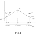
- FIG. 4 is a diagram illustrating the operation of the hinge device illustrated in FIG. 2 and a portable terminal having the same.
- FIG. 1 is an exploded perspective view of a portable terminal 100 having a hinge apparatus 200 according to an exemplary embodiment of the present invention
- FIG. 2 is an exploded perspective view of the hinge apparatus 200 in FIG. 1 .
- the hinge apparatus 200 can be applied to both a flip-type terminal and a folder-type terminal.
- a folder-type terminal will be described for illustrative purposes.
- the portable terminal 100 includes a first housing 101 , and a second housing 102 .
- One end of the second housing 102 is rotatably connected to the first housing 101 by the hinge apparatus 200 .
- the second housing 102 may be rotated away from the first housing 101 (i.e., opened) or rotated toward the first housing 101 (i.e., closed).
- the first hinge housing 101 has a key pad 111 and a transmitter 113 provided on a face thereof, and when the second housing 102 is rotated, the key pad 111 and the transmitter 113 are opened or closed.
- the top end of the first housing is provided with a pair of side hinge arms 115 which are opposed to each other.
- the second housing 102 has a display device 121 and a receiver 123 provided on a face thereof.
- the face of the second housing 102 is opposed to the first housing 101 when the second housing 102 is rotated toward the first housing 101 .
- the display device 121 and the receiver 123 are also opened or closed like the key pad 111 and the transmitter 113 when the second housing 102 is rotated.
- the second housing 102 is formed with a center hinge arm 125 at one end thereof, which is rotatably engaged between the side hinge arms 115 . As such, a hinge axis A of the terminal 100 is formed, and the second housing 102 is rotated about the hinge axis A.
- the center hinge arm 125 is formed with a hinge hole 127 at one end thereof so as to provide a space for mounting the hinge apparatus, and mounted with a hinge dummy (not shown) at the other end.
- the hinge apparatus 200 and the hinge dummy engage the side hinge arms 115 . Consequently, the center hinge arm 125 is rotatably engaged between the side hinge arms 115 by the hinge apparatus 200 and the hinge dummy.
- hinge apparatus 200 The construction of the hinge apparatus 200 will now be described with reference to FIGS. 2 to 4 .
- the hinge apparatus 200 includes a hinge housing 201 and a damping member 205 received within the hinge housing 201 .
- the damping member 205 rotates relative to the hinge housing 201 when the second housing 102 rotates.
- the hinge housing 201 has at least one guide groove 211 on an internal wall thereof, and the damping member 205 has at least one friction projection 253 .
- the damping member 205 has a pair of frictional projections 253 and the hinge housing 201 has a pair of guide grooves 211 .
- the frictional projections 253 are capable of moving in the guide grooves 211 .
- the frictional projections 253 move out from the guide grooves 211 over an interval from a position where the second housing 102 is folded onto the first housing 101 , and over an interval from a position where the second housing 102 is stopped while it is being rotated away from the first housing 101 , thereby rubbing against the internal wall of the hinge housing 201 . Therefore, even if the second housing 102 is provided with driving force during its rotation relative to the first housing 101 , the driving force is dampened at the moment the second housing 101 is folded onto the first housing (i.e., is closed) or at the moment the second housing 101 is stopped in the process of being rotated away from the first housing 101 (i.e. is opened).
- the hinge housing 201 is cylindrical, extends along the hinge axis A, and has flat faces 201 a on the outer circumferential surface thereof.
- the hinge hole 127 has a shape complementary with the shape of the hinge housing 201 so that the hinge housing 201 fits into the hinge hole 127 . Therefore, the hinge housing 201 rotates about the hinge axis A when the second housing 102 rotates relative to the first housing 101 .
- the hinge housing 201 is closed at one end thereof and open at the other end.
- the guide grooves 211 are formed on the internal wall of the closed end and extend by a predetermined angle along the circumferential direction of the hinge housing 201 .
- the angular extension range of the guide grooves 211 will be described in more detail in connection with the description of the opening and closing operation of the terminal 100 .
- the damping member 205 is circular and plate shaped and is positioned to contact the internal wall of the hinge housing 201 .
- the projections 253 on the face of the damping member face the internal wall.
- the damping member 205 is rotatably received within the hinge housing 201 so that the damping member 205 rotates relative to the hinge housing 201 when the second housing 102 rotates.
- the pair of frictional projections 253 are symmetrically arranged with reference to the rotational axis of the damping member 205 , i.e., with reference to the hinge axis A.
- the frictional projections 253 contact the internal wall of the hinge housing 201 from the opposite ends of the rotational extent of the second housing 102 , and move in the guide grooves 211 between the frictional sections.
- the frictional sections where the frictional projections 151 rub against the internal wall of the hinge housing 201 are referred to as first and third sections, respectively, and the section where the frictional projections 253 move in the guide grooves 211 is referred to as a second section.
- the first section is a section extending away from the position where the second housing 102 is folded onto the first housing 101 until the second section
- the second section is a section extending from the first section in the direction the second housing 102 moves away from the second housing 102
- the third section is a section extending from the end of the second section to the position where the second housing 102 is stopped when it rotates away from the first housing 101 .
- a pair of guide grooves 211 are provided and are arranged symmetrical to each other with reference to the hinge axis A.
- Each of the guide grooves 211 extends about 140 degrees along the circumferential direction of the hinge housing 201 .
- the second housing 102 is opened by about 160 degrees relative to the first housing 102 . This is because each of the frictional sections, over which the frictional projections 201 contact the internal wall of the hinge housing 201 , extends about 10 degrees at the rotational extent of the second housing 102 .
- the second housing 102 is adapted to rotate by receiving a driving force from the hinge apparatus 200 , the driving force will be dampened by the friction of the frictional projections 253 at the first and third sections. At the second section, however, the frictional projections 253 are positioned within the guide grooves 211 . As a result, no frictional force is produced, and the second housing is rotated by the driving force received from the hinge apparatus 200 .
- a lubricant such as grease may be introduced between the damping member 205 and the internal wall of the closed end of the hinge housing 201 to minimize friction between the damping member 205 and the internal wall of the closed end. Even if the lubricant is introduced between the damping member 205 and the internal wall of the closed end, the frictional projections 253 contact the internal wall of the closed end, thereby dampening the driving force supplied to the second housing 102 because the frictional projections are adapted to come into point-contact with the internal wall of the closed end.
- each of the guide grooves 211 can be varied, depending on the angular rotating range of the second housing 102 and the angular frictional range of the frictional projections 253 .
- each of the guide grooves 211 will extend about 130 degrees.
- the angular frictional range of each frictional projection 253 can be varied within the range of 10 degrees.
- the frictional range of each frictional projection 253 may be set to 5 degrees. In such a case, each of the guide grooves 211 can extend up to 150 degrees.
- the angular rotatable range of the second housing 102 the angular range of the frictional section of each frictional projection 253 , and the angular range of the extension of each guide groove 211 can all be varied.
- the hinge apparatus 200 includes a hinge shaft 202 , a hinge cam 203 , and an elastic member 204 to supply driving force to the second housing 102 .
- One end of the elastic member 204 is supported on the damping member 205 and provides an elastic force for biasing the damping member 205 into contact with the internal wall of the closed end of the hinge housing 201 .
- the hinge shaft 202 has a hinge projection 221 at a first end and a peak-shaped part 223 at a second end, and rotatably engages with the hinge housing 201 .
- a connection shaft 225 extends from the second end of the hinge shaft 201 along the hinge axis A.
- the connection shaft 225 extends through the hinge cam 203 , the elastic member 204 , and the damping member 205 , and projects from the closed end 201 of the hinge housing 201 through a hole 213 in the closed end.
- a coupling groove 227 is formed at the end of the connection shaft 225 .
- the coupling groove 227 is exposed to the outside of the closed end of the hinge housing 201 , and a support member 229 is engaged in the coupling groove 227 and abuts against the external wall of the closed end of the hinge housing 201 .
- the hinge shaft 202 is rotated relative to the hinge housing 201 and is held in place with respect to the hinge housing 201 .
- the hinge projection 221 projects from the first end of the hinge housing 201 , and the hinge housing 201 is mounted in the center hinge arm 125 .
- the hinge projection 221 is connected to one of the side hinge arm 115 .
- connection shaft 225 has flat surfaces 226
- the damping member 205 has a through-hole 251 , the shape of which corresponds to the cross-section of the connection shaft 225 .
- the connection shaft 225 engages the damping member 205 through the through-hole 251 , and the damping member 205 fits on the connection shaft in such a manner that the damping member 205 is restrained from rotation but is linearly movable on the connection shaft. Therefore, the damping member 205 is only linearly movable on the first housing 101 and is restrained from rotating, and when the second housing 102 rotates, the damping member 205 rotates relative to the hinge housing 201 .
- the hinge cam 203 is linearly movably received in the hinge housing 201 , and contacts the hinge shaft 202 by the elastic force of the elastic member 204 . Consequently, the elastic member 204 provides elastic force in a state in which it is supported by the hinge cam 203 at one end and supported by the damping member 205 at the other end. With the elastic force of the elastic member 204 , the damping member 205 contacts the internal wall of the hinge housing 201 and the hinge cam 203 contacts the hinge shaft 202 .
- the hinge cam 203 has flat faces on the circumferential surface thereof so that the shape of the hinge cam 203 is complementary with that of the hinge housing 201 . As a result, the hinge cam 203 is allowed to perform linear movement, but is restrained from rotation within the hinge housing 201 .
- the hinge cam 203 has a pair of peak-shaped parts 231 and a valley-shaped 233 part between the peak-shaped parts 231 , which are formed at one end of the hinge cam 203 .
- a hole 239 is formed through the hinge cam 203 in the direction of the hinge axis A so as to provide a path for the connection shaft 225 .
- the hinge cam 203 contacts the hinge shaft 202 due to the elastic force of the elastic member 204 , the valley-shaped part 233 and the peak-shaped part 223 of the hinge shaft engage each other.
- the elastic force of the elastic member 204 presses the hinge cam 203 into contact in the direction of the hinge shaft 202 , and the hinge shaft 202 rotates in a direction allowing the peak-shaped part 223 to engage the valley-shaped part 233 , thereby producing a driving force.
- the hinge apparatus 200 produces a driving force for rotating the hinge shaft 202 in a direction allowing the peak-shaped part 223 of the hinge shaft 202 to engage the valley-shaped part 233 .
- FIG. 4 is a cam diagram illustrating the operation of the hinge cam 203 .
- the second housing 102 can be opened up to 160 degrees from the position where it is folded onto the first housing 101 according to an exemplary embodiment of the present invention, wherein the second section corresponding to the guide grooves 211 extends by about 140 degrees, and the first and third sections are set to about 10 degrees, respectively.
- the hinge apparatus 200 produces a driving force acting in a direction allowing the peak-shaped part 223 of the hinge shaft to engage the valley-shaped part 233 , wherein the driving force acts as a force for stably holding the second housing 102 folded onto the first housing 101 .
- the frictional projections 251 are positioned out of the guide grooves 211 so that they contact the internal wall of the hinge housing 201 .
- the peak-shaped part 223 of the hinge shaft 202 moves toward the top point of the corresponding peak-shaped part 231 of the hinge cam 203 along the slope of the valley-shaped part 233 .
- the top point of the peak-shaped parts 231 of the hinge cam 203 is positioned at a point corresponding to the position of the second housing opened about 75 degrees from the first housing 101 .
- the peak-shaped part 223 of the hinge shaft 202 is positioned on the slope between the top point and the valley-shaped part 233 while the second housing 102 moves from its folded position to its 75 degrees opened position, and the hinge apparatus 200 produces a driving force acting in the direction of urging the first housing 101 to be folded onto the first housing 101 .
- the hinge apparatus 200 provides a driving force acting in the direction allowing the second housing 102 to be folded onto the first housing 101 .
- the section where the hinge apparatus 200 provides a driving force acting in the direction for urging the first housing 102 to be folded onto the first housing will be referred to as a “closing movement section.”
- the hinge apparatus 200 provides a driving force in the direction for rotating the second housing 102 away from the first housing 101 . This is because the hinge shaft 202 rotates in the direction for urging its peak-shaped part 223 to engage the valley-shaped part 233 . At this time, the direction of rotating the hinge shaft 202 is changed by the cam diagram of the hinge cam.
- the section where the hinge apparatus 200 provides a driving force acting in the direction for urging the first housing to rotate away from the first housing will be referred to as an “opening movement section.”
- the second housing 102 receives driving force acting in a direction for urging the second housing 102 to be folded onto the first housing 101 or to move away from the first housing 101 , depending on the angle to which it is opened.
- a conventional hinge apparatuses supplies a driving force merely by converting elastic force provided by an elastic member into a rotational force
- a separate shock absorbing material for dampening the impact produced at the moment one housing of a terminal is folded onto the other housing or at the moment the rotation of one housing is stopped while being opened is typically provided.
- the hinge apparatus 200 includes the damping member 205 to dampen the driving force at the moment the rotation of the second housing 102 is stopped. That is, the driving force is dampened when the second housing 102 is folded onto the first housing 101 or when the second housing is completely opened by about 160 degrees. As a result, the impact and load applied to the terminal 100 can be reduced.
- the damping member 205 In the first section from the folded position onto the first housing 101 to the 10 degrees opened position of the second housing 102 , the damping member 205 produces a frictional force so as to dampen the driving force for rotating the second housing 102 . In addition, in the third section, from the 160 degrees opened position from the first housing 101 to the 150 degrees opened position of the second housing 102 , the damping member 205 also produces a frictional force so as to dampen the driving force for rotating the second housing 102 .
- the frictional projections 253 are positioned within the guide grooves 211 and do not produce a frictional force. As a result, the second housing 102 is rotated by the driving force rotating the hinge shaft 202 .
- the angle of the first section is smaller than that of the closing movement section while the first section is included in the closing movement section.
- the angle of the second section is an angle smaller than that of the opening movement section while the second section is included in the opening movement section. That is, the guide grooves 211 partially overlap with the closing movement section as well as with the opening movement section. Therefore, the damping member 205 produces the frictional force only at a part of the closing movement section and a part of the opening movement section, where the guide grooves 211 do not overlap with the closing movement section and the opening movement section, so as to dampen the driving force produced by the hinge apparatus 200 .
- the damping member 205 produces the frictional force from the moment the frictional projections 251 move out of the guide grooves 211 and enter the third section, so as to dampen the driving force produced by the hinge apparatus 200 . From the moment the frictional projections 251 move out of the guide grooves 211 and enter the third section to the moment the second housing 102 is stopped after rotating 160 degrees, the rotating velocity of the second housing 102 is gradually reduced.
- the hinge apparatus for a portable terminal dampens the impact produced at the moment the housings of the terminal are folded or stopped to rotate after being opened from each other by a predetermined angle, thereby preventing damage to the circuit devices.
- the hinge apparatus improves the endurance and the structural stability of the terminal.
- the costs required for testing the endurance and the structural stability in the process of manufacturing terminals, and the costs required for maintaining and repairing such terminals can be reduced.
Landscapes
- Engineering & Computer Science (AREA)
- Signal Processing (AREA)
- Computer Networks & Wireless Communication (AREA)
- Telephone Set Structure (AREA)
- Pivots And Pivotal Connections (AREA)
Abstract
Description
Claims (31)
Applications Claiming Priority (2)
| Application Number | Priority Date | Filing Date | Title |
|---|---|---|---|
| KR1020060113297A KR100790175B1 (en) | 2006-11-16 | 2006-11-16 | Hinge device and method of operating a portable terminal having the same |
| KR2006-113297 | 2006-11-16 |
Publications (2)
| Publication Number | Publication Date |
|---|---|
| US20080118057A1 US20080118057A1 (en) | 2008-05-22 |
| US7613293B2 true US7613293B2 (en) | 2009-11-03 |
Family
ID=39216179
Family Applications (1)
| Application Number | Title | Priority Date | Filing Date |
|---|---|---|---|
| US11/758,481 Expired - Fee Related US7613293B2 (en) | 2006-11-16 | 2007-06-05 | Hinge apparatus for a portable terminal and portable terminal having the same |
Country Status (2)
| Country | Link |
|---|---|
| US (1) | US7613293B2 (en) |
| KR (1) | KR100790175B1 (en) |
Cited By (1)
| Publication number | Priority date | Publication date | Assignee | Title |
|---|---|---|---|---|
| US20150145397A1 (en) * | 2013-11-26 | 2015-05-28 | Lg Electronics Inc. | Home appliance |
Families Citing this family (9)
| Publication number | Priority date | Publication date | Assignee | Title |
|---|---|---|---|---|
| JP2007321835A (en) | 2006-05-31 | 2007-12-13 | Matsushita Electric Ind Co Ltd | Damper device |
| KR100976115B1 (en) * | 2008-01-16 | 2010-08-16 | (주)엘티엠에이피 | Damping Folder Hinge Module |
| KR101013742B1 (en) * | 2008-10-21 | 2011-02-14 | 케이. 에이. 이 (주) | Hinge Assembly for Mobile Communication Terminal |
| CN101929502B (en) * | 2008-12-31 | 2013-03-13 | 深圳富泰宏精密工业有限公司 | Hinge structure and portable electronic device using same |
| US8621714B2 (en) * | 2008-12-31 | 2014-01-07 | Shenzhen Futaihong Precision Industry Co., Ltd. | Hinge assembly for foldable electronic device |
| KR101042916B1 (en) | 2009-01-21 | 2011-06-20 | (주)나라테크놀로지 | Hinge device for a cellular phone |
| US7798297B1 (en) | 2009-06-30 | 2010-09-21 | Nokia Corporation | Handheld apparatus and motion dampener for the same |
| CN211778479U (en) * | 2019-07-15 | 2020-10-27 | 深圳市柔宇科技有限公司 | Folding device and electronic equipment |
| CN114893494B (en) * | 2022-07-12 | 2022-11-11 | 荣耀终端有限公司 | Damping mechanism and terminal |
Citations (3)
| Publication number | Priority date | Publication date | Assignee | Title |
|---|---|---|---|---|
| US6292980B1 (en) | 1998-05-26 | 2001-09-25 | Samsung Electronics Co., Ltc. | Hinge mechanism of portable phone |
| KR20050031563A (en) | 2003-09-30 | 2005-04-06 | 캠아이티(주) | Hinge assembly of mobile terminal |
| KR20050032788A (en) | 2003-10-02 | 2005-04-08 | 주식회사 팬택 | Shock-absorbing structure for cover opening of folding type communication terminal |
-
2006
- 2006-11-16 KR KR1020060113297A patent/KR100790175B1/en not_active Expired - Fee Related
-
2007
- 2007-06-05 US US11/758,481 patent/US7613293B2/en not_active Expired - Fee Related
Patent Citations (3)
| Publication number | Priority date | Publication date | Assignee | Title |
|---|---|---|---|---|
| US6292980B1 (en) | 1998-05-26 | 2001-09-25 | Samsung Electronics Co., Ltc. | Hinge mechanism of portable phone |
| KR20050031563A (en) | 2003-09-30 | 2005-04-06 | 캠아이티(주) | Hinge assembly of mobile terminal |
| KR20050032788A (en) | 2003-10-02 | 2005-04-08 | 주식회사 팬택 | Shock-absorbing structure for cover opening of folding type communication terminal |
Cited By (2)
| Publication number | Priority date | Publication date | Assignee | Title |
|---|---|---|---|---|
| US20150145397A1 (en) * | 2013-11-26 | 2015-05-28 | Lg Electronics Inc. | Home appliance |
| US9435545B2 (en) * | 2013-11-26 | 2016-09-06 | Lg Electronics Inc. | Home appliance |
Also Published As
| Publication number | Publication date |
|---|---|
| US20080118057A1 (en) | 2008-05-22 |
| KR100790175B1 (en) | 2008-01-02 |
Similar Documents
| Publication | Publication Date | Title |
|---|---|---|
| US7613293B2 (en) | Hinge apparatus for a portable terminal and portable terminal having the same | |
| US6618903B2 (en) | Hinge device | |
| US10000955B2 (en) | Biaxial hinge and terminal device using the same | |
| US7036186B2 (en) | Swing hinge device for a portable terminal | |
| US7337498B2 (en) | Electronic device and hinge assembly thereof | |
| KR100490356B1 (en) | Rotary type hinge device for portable wireless terminal | |
| CN101512093B (en) | Furniture hinge | |
| US7634838B2 (en) | Hinge and a mobile phone with the hinge | |
| KR20090107676A (en) | Hinge and mobile terminal having same | |
| KR20050039579A (en) | Hinge for a portable terminal | |
| US8996079B2 (en) | Portable terminal with multiple-hinges | |
| US7530145B2 (en) | Cover restricting mechanism for foldable electronic device | |
| CN102072246B (en) | Hinge structure and electronic device with same | |
| WO2006085461A1 (en) | Device for opening and closing door | |
| US7404235B2 (en) | Hinge assembly for portable electronic devices | |
| US20060245586A1 (en) | Hinge assembly for a foldable electronic device | |
| KR200382516Y1 (en) | Sliding type opening and closing mechanism of cellular phone | |
| KR100575757B1 (en) | Foldable handheld terminal with hinge buffer | |
| KR101044594B1 (en) | Hinge shock absorber of mobile phone | |
| TWM668314U (en) | Double axis pivot with locking function | |
| KR100663449B1 (en) | Portable terminal having a rotary hinge device | |
| KR20060062172A (en) | Hinge device | |
| US20100107367A1 (en) | Rotary hinge module and folder type mobile communication terminal having the same | |
| KR20060055168A (en) | Handheld terminal with rotatable hinge pile | |
| JP2010223385A (en) | Hinge mechanism and electronic equipment mounted therewith |
Legal Events
| Date | Code | Title | Description |
|---|---|---|---|
| AS | Assignment |
Owner name: SAMSUNG ELECTRONICS CO. LTD., KOREA, REPUBLIC OF Free format text: ASSIGNMENT OF ASSIGNORS INTEREST;ASSIGNORS:SON, KI-BOK;KO, BYUNG-YEOL;CHOI, JONG-HWAN;REEL/FRAME:019384/0305 Effective date: 20070604 |
|
| STCF | Information on status: patent grant |
Free format text: PATENTED CASE |
|
| FEPP | Fee payment procedure |
Free format text: PAYOR NUMBER ASSIGNED (ORIGINAL EVENT CODE: ASPN); ENTITY STATUS OF PATENT OWNER: LARGE ENTITY |
|
| FEPP | Fee payment procedure |
Free format text: PAYER NUMBER DE-ASSIGNED (ORIGINAL EVENT CODE: RMPN); ENTITY STATUS OF PATENT OWNER: LARGE ENTITY Free format text: PAYOR NUMBER ASSIGNED (ORIGINAL EVENT CODE: ASPN); ENTITY STATUS OF PATENT OWNER: LARGE ENTITY |
|
| FPAY | Fee payment |
Year of fee payment: 4 |
|
| FPAY | Fee payment |
Year of fee payment: 8 |
|
| FEPP | Fee payment procedure |
Free format text: MAINTENANCE FEE REMINDER MAILED (ORIGINAL EVENT CODE: REM.); ENTITY STATUS OF PATENT OWNER: LARGE ENTITY |
|
| LAPS | Lapse for failure to pay maintenance fees |
Free format text: PATENT EXPIRED FOR FAILURE TO PAY MAINTENANCE FEES (ORIGINAL EVENT CODE: EXP.); ENTITY STATUS OF PATENT OWNER: LARGE ENTITY |
|
| STCH | Information on status: patent discontinuation |
Free format text: PATENT EXPIRED DUE TO NONPAYMENT OF MAINTENANCE FEES UNDER 37 CFR 1.362 |
|
| FP | Lapsed due to failure to pay maintenance fee |
Effective date: 20211103 |