US7613075B2 - Adaptive high frequency laser sonar system - Google Patents
Adaptive high frequency laser sonar system Download PDFInfo
- Publication number
- US7613075B2 US7613075B2 US11/761,536 US76153607A US7613075B2 US 7613075 B2 US7613075 B2 US 7613075B2 US 76153607 A US76153607 A US 76153607A US 7613075 B2 US7613075 B2 US 7613075B2
- Authority
- US
- United States
- Prior art keywords
- acoustic
- housing
- window
- acoustic window
- scanning laser
- Prior art date
- Legal status (The legal status is an assumption and is not a legal conclusion. Google has not performed a legal analysis and makes no representation as to the accuracy of the status listed.)
- Expired - Fee Related, expires
Links
Images


Classifications
-
- H—ELECTRICITY
- H04—ELECTRIC COMMUNICATION TECHNIQUE
- H04B—TRANSMISSION
- H04B11/00—Transmission systems employing ultrasonic, sonic or infrasonic waves
-
- H—ELECTRICITY
- H04—ELECTRIC COMMUNICATION TECHNIQUE
- H04B—TRANSMISSION
- H04B10/00—Transmission systems employing electromagnetic waves other than radio-waves, e.g. infrared, visible or ultraviolet light, or employing corpuscular radiation, e.g. quantum communication
- H04B10/11—Arrangements specific to free-space transmission, i.e. transmission through air or vacuum
- H04B10/112—Line-of-sight transmission over an extended range
- H04B10/1121—One-way transmission
Definitions
- the present invention relates generally to acoustic sensors, and in particular to a laser vibrometer acoustic sensor for use in underwater applications.
- Sonar systems traditionally use an array of pressure-sensing hydrophones to detect underwater sound.
- the individual hydrophones (or array elements) are configured in a linear, planar, or conformal grid and then the output voltage from each hydrophone is summed. Fundamentally, the hydrophone converts the underwater acoustic pressure to a calibrated voltage.
- Array sampling theory requires that the separation between the array elements be no greater than one half the acoustic wavelength at the array's upper design frequency.
- Pressure sensors or hydrophones are commonly used in these acoustic arrays. These sensors are made of piezoelectric ceramic materials which convert mechanical stresses in the ceramic due to an incident acoustic pressure into a calibrated output voltage. More recently, acoustic velocity sensors have been used in acoustic arrays. These velocity sensors also use ceramic's piezoelectric properties to convert acoustic particle velocity to an output voltage. Thus, the acoustic frequencies utilized by the array are limited by the sensor spacing
- Scanning laser vibrometers are well known in the prior art. These include commercially available systems such as the Polytec® Model PSV-100 Scanning Laser Vibrometer System (SLVS). This system can sample a grid of 512 by 512 points, with each grid point having a spot size of 0.0004 inches. The output of the SLVS provides an indication of the velocities of an object at the grid points to indicate vibrations of the object.
- SLVS Polytec® Model PSV-100 Scanning Laser Vibrometer System
- Walsh et al. in U.S. Pat. No. 6,188,644 teach a photon transducer system is provided for obtaining information on acoustic signals within a fluid environment.
- the photon transducer system uses a laser-based Doppler interferometer located within a pressure release surface.
- the pressure release surface is formed by generating a gas pocket in the fluid, creating a boundary layer between the laser light source and the surrounding fluid.
- Laser light is reflected from the boundary and is detected by the interferometer to obtain the Doppler velocity of the pressure release surface.
- the pressure incident on the boundary can be determined from the measured velocity, providing information on the incident acoustic pressure.
- a submarine bow dome acoustic sensor assembly that comprises an outer hull bow portion, an inner pressure hull wall extending athwartships and in conjunction with the outer hull bow portion defining a free-flood compartment, and an acoustic bow panel disposed in the compartment and connected to the pressure hull wall by acoustically isolating supports.
- a laser scanner is disposed in the compartment and is oriented so as to project a laser beam onto a surface of the acoustic bow panel, and a sensor is disposed in the compartment and oriented so as to receive reflections of the laser beam off the acoustic panel and to transmit data from which a position of a sound generating source can be determined.
- Antonelli et al. in U.S. patent application Ser. No. 11/070,400 teach an acoustic sensor used in underwater applications.
- the sensor includes a reflective material adhered to one side of a structure, such as an outer submarine hull or any marine vessel hull.
- a laser interferometer is placed on the side of the structure with the reflective material.
- the laser interferometer sends a plurality of laser beams, in sequence or all at one time, to a plurality of points across the retro-reflective material.
- the laser beams reflect back to the interferometer, which captures the reflected beams using receiving optics.
- the phase modulation of the reflected laser beams is compared to a reference laser beam within the interferometer to obtain the vibration velocity characteristics of the hull surface structure. Since the reflective material is adhered to the structure, the structure vibration is the same as the vibration of the reflective material. From this vibration, the acoustic pressure associated with the structure may be calculated.
- Walsh et al. provide for measurement of characteristics of a pressure release surface on the exterior of an underwater vehicle. It is suggested that various characteristics of the disclosed system make it unsuitable for use as an underwater acoustic sensor.
- the laser interferometer is not capable of scanning the boundary surface to conduct beamforming. The boundary surface is not sufficiently stable to clearly determine acoustic vibrations. Furthermore, the laser interferometer is not insulated from vehicle vibrations.
- Glenning et al. use a scanning laser for measurement of vibrations impinging on a bow panel located in a free flood area of an underwater vehicle. During a test of a similar system, it was found that at oblique angles, the incident sound field insonified both the panel and the acoustic lens of the underwater housing containing the laser. This distorted the time series measurements made on the surface of the panel. It was also found that water particles in the path of the laser were insonified further distorting the acoustic waves.
- Antonelli et al. disclose an air/water acoustic window, but they don't disclose the use of vibration isolation for the window and the laser vibrometer. As above, it has been found that this lack of isolation interferes with the reception of external acoustic signals.
- the adaptive high frequency laser sonar system includes a housing having an internal cavity filled with a vibration decoupling medium.
- An acoustic window formed of an acoustically transparent material is mounted in the housing. This mounting can be by antivibration mounts to prevent housing noise from affecting the acoustic window.
- a scanning laser vibrometer is positioned within the housing and directed to detect vibrations of the acoustic window. Antivibration mounts are joined between said scanning laser vibrometer and the housing. In further embodiments, the scanning laser vibrometer detects vibrations at a plurality of locations on the acoustic window forming a virtual array.
- the scanning laser vibrometer scans the surface of the acoustic window to detect its surface velocity which is directly proportional to the incident acoustic pressure. This sampling creates essentially a continuous acoustic aperture—the upper cut-off frequency for such a finely sampled array would be 74 MHz. Acoustic grating lobes would be eliminated at all frequencies of practical interest.
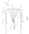
- FIG. 1 is a diagram showing acoustic pressure waves impinging on a thin plate in a fluid
- FIG. 2 is diagram of the sonar system of the current invention.
- FIG. 3 is a diagram of the sonar system of the current invention showing the inner workings of the laser vibrometry system and further showing the virtual array capability of the invention.
- p(x,t) is acoustic pressure
- ⁇ cv(x,t) is the product of the medium's characteristic impedance ⁇ c and acoustic particle velocity v(x,t).
- FIG. 1 consider a thin plate (or membrane) of thickness h, insonified by an acoustic plane wave of amplitude P i as seen in FIG. 1 , with reflected and transmitted amplitudes, P r and P t , respectively.
- a thin membrane beneath an acoustically transparent coating would have a velocity response proportional to the incident acoustic field.
- the membrane thickness would need to be on the order of 1/10 of an inch ( ⁇ 2.5 mm).
- Thicker plates may, however, be accommodated.
- Thicker elastic plates allow for transverse and in-plane vibrations, with the plate's mode shapes being primarily governed by flexure.
- the wavenumbers corresponding to flexural modes are well separated and are outside of the wavenumbers within the acoustic region.
- Many signal processing techniques can be employed to adaptively filter the nonacoustic high-wavenumber components from the desired acoustic wavenumbers.
- FIG. 2 illustrates the high-frequency laser sonar system 12 configured for a cylinder.
- This cylinder could be a nose of an underwater vehicle such as a torpedo.
- a scanning laser vibrometer system 14 is positioned on a vibration isolation member 16 within a cylinder 18 .
- Cylinder 18 can be an underwater vehicle nose cone.
- An acoustic window 20 is positioned at a forward portion of cylinder 18 .
- the inner surface of acoustic window 20 can have a reflective coating 22 positioned thereon.
- Acoustic window 20 is surrounded by vibration isolation material 24 where it joins cylinder 18 .
- Scanning laser vibrometer 14 is located at a standoff distance “d” from the reflective coating 22 on the inner surface of acoustic window 20 .
- a representative acoustic plane wave 26 is shown outside of the cylinder 18 . Beams 28 from scanning laser vibrometer system 14 are shown within the cylinder 18 .
- the region 30 of cylinder 18 between vibrometer system 14 and reflective coating 22 is filled with a transparent, vibration decoupling medium.
- this material is a gas that decouples vibrations from the underwater vehicle that could interfere with beams 28 and provide spurious signals.
- this material could also be a low pressure gas or vacuum.
- FIG. 3 shows a virtual sensor array created when beams 28 from scanning laser vibrometer system 14 are reflected from reflective coating 22 .
- Laser vibrometer system 14 uses at least one laser beam 32 to monitor the reflective coating 22 at a plurality of sensor locations 34 .
- the current invention utilizes a 512 ⁇ 512 array of sensor locations 34 forming virtual sensor array 36 ; however, other numbers and configurations of sensor locations can be created within the scope of this invention.
- a laser 38 within the laser vibrometer 14 provides laser beam 32 which is split by a splitter 40 into a reference portion 42 and a sensor portion 44 .
- the sensor portion 44 travels through a scanning mirror 46 and is reflected off of the reflective coating 22 at sensor location 34 . This results in a reflected portion 48 which returns to laser vibrometer system.
- Reference portion 42 is typically reflected off a reference mirror 50 and returns to splitter 40 .
- the reflected portion 48 and the reference portion 42 are then combined at splitter 50 .
- An interference beam 52 formed by interference between the two beam portions is received at a photodetector 54 which produces a signal representing the velocity of the reflective coating 22 at the sensor location 34 .
- Either surface displacement (by counting interference fringes) or surface velocity (by detecting the Doppler shift due to the motion of the surface) can be measured by vibrometer system 14 .
- surface velocity is used.
- An additional and known oscillator signal, at frequency f rf is added to the signal received by the photodetector. In this manner, the polarity or velocity direction can be determined. This allows monitoring of vibrations at each sensor location 34 .
- a signal processing system 56 can then use these velocities to form acoustic beams as is well known in the art.
- Scanning laser vibrometer system 14 can be similar to a commercially available system such as the Polytec® Model PSV-100 SLVS. This system features a velocity resolution down to 0.25 ⁇ m/s semipeak in a 1 Hz bandwidth, independent of frequency. However, for fast Fourier transform (FFT) temporal processing, the maximum sampling rate of the data acquisition system is 400 kHz (with a 2048 point FFT), which limits the upper frequency for two channel measurements to approximately 200 kHz. Voltage time signals can be taken directly if faster processing is necessary.
- FFT fast Fourier transform
- deflection mirrors such as 46, automatically steer the helium-neon (He—Ne) laser beam (at a wavelength of 633 nm) within a 40° ⁇ 40° (horizontal by vertical) field of view on to the vibrating surface.
- He—Ne helium-neon
- a simple geometry calculation determines the required standoff distance d for a field of view ⁇ and a given aperture size L:
- the scan resolution of the commercial SLVS is stated to be very precise at 0.01° (the corresponding point-to-point positional resolution would be determined from the surface-to-photodetector standoff distance).
- the normal component of velocity is always measured.
- the system automatically compensates via a cosine correction.
Landscapes
- Engineering & Computer Science (AREA)
- Computer Networks & Wireless Communication (AREA)
- Signal Processing (AREA)
- Physics & Mathematics (AREA)
- Electromagnetism (AREA)
- Measurement Of Mechanical Vibrations Or Ultrasonic Waves (AREA)
Abstract
Description
p(x,t)=ρcv(x,t), (1)
where p(x,t) is acoustic pressure and ρcv(x,t) is the product of the medium's characteristic impedance ρc and acoustic particle velocity v(x,t). Thus, measuring acoustic pressure with an array of conventional hydrophones is equivalent to measuring acoustic particle velocity with an array of velocity sensors. This equivalence has been the basis for sonobuoy designs for decades and, more recently, for innovative submarine sonar systems.
The amplitude of the plate's velocity is V=|v|. A force balance between each plate boundary yields
(P i +P r)A=F(0), (3)
P t A=F(h), and (4)
F(0)−F(h)=iωρ 1 hAV=(P i +P r)A−P t A. (5)
where A is a unit surface area, ρi is the plate's density, and i is √{square root over (−1)}. Combining equations (2) and (5) yields the incident pressure to window velocity transfer function,
where ω is the angular frequency of harmonic excitation. Note that as h→0, equation (6) reduces to Euler's equation, Pi=ρcV, and the plate's velocity is directly proportional to the incident acoustic pressure. This is, of course, a simplification.
Claims (9)
Priority Applications (1)
| Application Number | Priority Date | Filing Date | Title |
|---|---|---|---|
| US11/761,536 US7613075B2 (en) | 2007-06-12 | 2007-06-12 | Adaptive high frequency laser sonar system |
Applications Claiming Priority (1)
| Application Number | Priority Date | Filing Date | Title |
|---|---|---|---|
| US11/761,536 US7613075B2 (en) | 2007-06-12 | 2007-06-12 | Adaptive high frequency laser sonar system |
Publications (2)
| Publication Number | Publication Date |
|---|---|
| US20080310256A1 US20080310256A1 (en) | 2008-12-18 |
| US7613075B2 true US7613075B2 (en) | 2009-11-03 |
Family
ID=40132170
Family Applications (1)
| Application Number | Title | Priority Date | Filing Date |
|---|---|---|---|
| US11/761,536 Expired - Fee Related US7613075B2 (en) | 2007-06-12 | 2007-06-12 | Adaptive high frequency laser sonar system |
Country Status (1)
| Country | Link |
|---|---|
| US (1) | US7613075B2 (en) |
Cited By (3)
| Publication number | Priority date | Publication date | Assignee | Title |
|---|---|---|---|---|
| US8542413B2 (en) | 2009-02-23 | 2013-09-24 | 2G Robotics Inc. | Laser scanner assembly |
| US8599649B1 (en) | 2010-03-09 | 2013-12-03 | The United States Of America As Represented By The Secretary Of The Navy | Laser-based method of detecting underwater sound through an ice layer |
| US9459238B1 (en) | 2011-03-14 | 2016-10-04 | Raytheon Company | Methods and apparatus for using acoustic inspection of containers to image objects |
Citations (5)
| Publication number | Priority date | Publication date | Assignee | Title |
|---|---|---|---|---|
| US4155065A (en) * | 1977-09-12 | 1979-05-15 | The United States Of America As Represented By The Secretary Of The Navy | Optic scattering acoustic transducer |
| US4446543A (en) * | 1979-07-02 | 1984-05-01 | The United States Of America As Represented By The Secretary Of The Navy | Optical resonator single-mode fiber hydrophone |
| US6188644B1 (en) | 1999-05-10 | 2001-02-13 | The United States Of America As Represented By The Secretary Of The Navy | Photon transducer |
| US6349791B1 (en) | 2000-04-03 | 2002-02-26 | The United States Of America As Represented By The Secretary Of The Navy | Submarine bow dome acoustic sensor assembly |
| US20020149998A1 (en) * | 2001-03-07 | 2002-10-17 | Phillips Petroleum Company | Method and apparatus for measuring seismic energy imparted to the earth |
-
2007
- 2007-06-12 US US11/761,536 patent/US7613075B2/en not_active Expired - Fee Related
Patent Citations (5)
| Publication number | Priority date | Publication date | Assignee | Title |
|---|---|---|---|---|
| US4155065A (en) * | 1977-09-12 | 1979-05-15 | The United States Of America As Represented By The Secretary Of The Navy | Optic scattering acoustic transducer |
| US4446543A (en) * | 1979-07-02 | 1984-05-01 | The United States Of America As Represented By The Secretary Of The Navy | Optical resonator single-mode fiber hydrophone |
| US6188644B1 (en) | 1999-05-10 | 2001-02-13 | The United States Of America As Represented By The Secretary Of The Navy | Photon transducer |
| US6349791B1 (en) | 2000-04-03 | 2002-02-26 | The United States Of America As Represented By The Secretary Of The Navy | Submarine bow dome acoustic sensor assembly |
| US20020149998A1 (en) * | 2001-03-07 | 2002-10-17 | Phillips Petroleum Company | Method and apparatus for measuring seismic energy imparted to the earth |
Non-Patent Citations (1)
| Title |
|---|
| Benjamin A. Cray, Stephen E. Forsythe, Andrew J. Hull and Lee E. Estes, A Scanning Laser Doppler Vibrometer Acoustic Array, paper, Jul. 2006, pp. 164-170, vol. 120, No. 1, Journal Acoustic Society of America, USA. |
Cited By (4)
| Publication number | Priority date | Publication date | Assignee | Title |
|---|---|---|---|---|
| US8542413B2 (en) | 2009-02-23 | 2013-09-24 | 2G Robotics Inc. | Laser scanner assembly |
| US8599649B1 (en) | 2010-03-09 | 2013-12-03 | The United States Of America As Represented By The Secretary Of The Navy | Laser-based method of detecting underwater sound through an ice layer |
| US9459238B1 (en) | 2011-03-14 | 2016-10-04 | Raytheon Company | Methods and apparatus for using acoustic inspection of containers to image objects |
| US9482506B1 (en) | 2011-03-14 | 2016-11-01 | Raytheon Company | Methods and apparatus for non-contact inspection of containers using multiple sensors |
Also Published As
| Publication number | Publication date |
|---|---|
| US20080310256A1 (en) | 2008-12-18 |
Similar Documents
| Publication | Publication Date | Title |
|---|---|---|
| US6081481A (en) | Method for detecting buried objects by measuring seismic vibrations induced by acoustical coupling with a remote source of sound | |
| US5504719A (en) | Laser hydrophone and virtual array of laser hydrophones | |
| US6008887A (en) | Single beam laser surface velocity and displacement measurement apparatus | |
| US4554836A (en) | Laser vibrometer | |
| RU2546997C2 (en) | Seismic recording system with rejection of ghost wave and movement | |
| Silvia et al. | A theoretical and experimental investigation of low-frequency acoustic vector sensors | |
| US20050146726A1 (en) | Fiber tip based sensor system for measurements of pressure gradient, air particle velocity and acoustic intensity | |
| US6697302B1 (en) | Highly directive underwater acoustic receiver | |
| US20230132220A1 (en) | Dual acoustic pressure and hydrophone sensor array system | |
| US20030072219A1 (en) | Laser velocimetry detection of underwater sound | |
| US6594290B2 (en) | Dynamic change detecting method, dynamic change detecting apparatus and ultrasonic diagnostic apparatus | |
| US7613075B2 (en) | Adaptive high frequency laser sonar system | |
| KR20160052656A (en) | Acoustic converter, acoustic converter system, optical hydrophone, acoustic converter array and watercraft | |
| Lee et al. | Microcomputer-controlled acoustic rangefinding technique | |
| US7259864B1 (en) | Optical underwater acoustic sensor | |
| Cray | Adaptive High Frequency Laser Sonar System | |
| KR200184719Y1 (en) | Underwater investigation device | |
| Cray et al. | A scanning laser Doppler vibrometer acoustic array | |
| EP3852387A1 (en) | Sound detection device | |
| JP2001304952A (en) | Ultrasonic sound pressure sensor | |
| Peller et al. | Fast sound field characterization of beamforming capable capacitive micromachined ultrasonic transducer (CMUT) arrays by refracto-vibrometry | |
| US20250306190A1 (en) | Acoustic vector sensor | |
| Reusser et al. | SPACECRAFT LEAK LOCATION USING STRUCTURE‐BORNE NOISE | |
| Djelouah et al. | Pulsed calibration technique of miniature ultrasonic receivers using a wideband laser interferometer | |
| Smith et al. | High-frequency acoustic phase stability measurement system |
Legal Events
| Date | Code | Title | Description |
|---|---|---|---|
| AS | Assignment |
Owner name: COUNSEL, THE UNITED STATES OF AMERICA NAVAL UNDERS Free format text: ASSIGNMENT OF ASSIGNORS INTEREST;ASSIGNORS:CRAY, BENJAMIN A.;BOOHER, WALTER H.;FORSYTHE, STEPHEN B.;AND OTHERS;REEL/FRAME:019474/0874 Effective date: 20070321 |
|
| FPAY | Fee payment |
Year of fee payment: 4 |
|
| REMI | Maintenance fee reminder mailed | ||
| LAPS | Lapse for failure to pay maintenance fees |
Free format text: PATENT EXPIRED FOR FAILURE TO PAY MAINTENANCE FEES (ORIGINAL EVENT CODE: EXP.) |
|
| STCH | Information on status: patent discontinuation |
Free format text: PATENT EXPIRED DUE TO NONPAYMENT OF MAINTENANCE FEES UNDER 37 CFR 1.362 |
|
| FP | Expired due to failure to pay maintenance fee |
Effective date: 20171103 |