US760102A - Artificial limb. - Google Patents
Artificial limb. Download PDFInfo
- Publication number
- US760102A US760102A US17428803A US1903174288A US760102A US 760102 A US760102 A US 760102A US 17428803 A US17428803 A US 17428803A US 1903174288 A US1903174288 A US 1903174288A US 760102 A US760102 A US 760102A
- Authority
- US
- United States
- Prior art keywords
- hand
- fingers
- shaft
- artificial
- crank
- Prior art date
- Legal status (The legal status is an assumption and is not a legal conclusion. Google has not performed a legal analysis and makes no representation as to the accuracy of the status listed.)
- Expired - Lifetime
Links
Images

Classifications
-
- A—HUMAN NECESSITIES
- A61—MEDICAL OR VETERINARY SCIENCE; HYGIENE
- A61F—FILTERS IMPLANTABLE INTO BLOOD VESSELS; PROSTHESES; DEVICES PROVIDING PATENCY TO, OR PREVENTING COLLAPSING OF, TUBULAR STRUCTURES OF THE BODY, e.g. STENTS; ORTHOPAEDIC, NURSING OR CONTRACEPTIVE DEVICES; FOMENTATION; TREATMENT OR PROTECTION OF EYES OR EARS; BANDAGES, DRESSINGS OR ABSORBENT PADS; FIRST-AID KITS
- A61F2/00—Filters implantable into blood vessels; Prostheses, i.e. artificial substitutes or replacements for parts of the body; Appliances for connecting them with the body; Devices providing patency to, or preventing collapsing of, tubular structures of the body, e.g. stents
- A61F2/50—Prostheses not implantable in the body
- A61F2/54—Artificial arms or hands or parts thereof
- A61F2/58—Elbows; Wrists ; Other joints; Hands
- A61F2/583—Hands; Wrist joints
- A61F2/588—Hands having holding devices shaped differently from human fingers, e.g. claws, hooks, tubes
-
- A—HUMAN NECESSITIES
- A61—MEDICAL OR VETERINARY SCIENCE; HYGIENE
- A61F—FILTERS IMPLANTABLE INTO BLOOD VESSELS; PROSTHESES; DEVICES PROVIDING PATENCY TO, OR PREVENTING COLLAPSING OF, TUBULAR STRUCTURES OF THE BODY, e.g. STENTS; ORTHOPAEDIC, NURSING OR CONTRACEPTIVE DEVICES; FOMENTATION; TREATMENT OR PROTECTION OF EYES OR EARS; BANDAGES, DRESSINGS OR ABSORBENT PADS; FIRST-AID KITS
- A61F2/00—Filters implantable into blood vessels; Prostheses, i.e. artificial substitutes or replacements for parts of the body; Appliances for connecting them with the body; Devices providing patency to, or preventing collapsing of, tubular structures of the body, e.g. stents
- A61F2/50—Prostheses not implantable in the body
- A61F2/54—Artificial arms or hands or parts thereof
- A61F2/58—Elbows; Wrists ; Other joints; Hands
- A61F2/583—Hands; Wrist joints
-
- A—HUMAN NECESSITIES
- A61—MEDICAL OR VETERINARY SCIENCE; HYGIENE
- A61F—FILTERS IMPLANTABLE INTO BLOOD VESSELS; PROSTHESES; DEVICES PROVIDING PATENCY TO, OR PREVENTING COLLAPSING OF, TUBULAR STRUCTURES OF THE BODY, e.g. STENTS; ORTHOPAEDIC, NURSING OR CONTRACEPTIVE DEVICES; FOMENTATION; TREATMENT OR PROTECTION OF EYES OR EARS; BANDAGES, DRESSINGS OR ABSORBENT PADS; FIRST-AID KITS
- A61F2/00—Filters implantable into blood vessels; Prostheses, i.e. artificial substitutes or replacements for parts of the body; Appliances for connecting them with the body; Devices providing patency to, or preventing collapsing of, tubular structures of the body, e.g. stents
- A61F2/50—Prostheses not implantable in the body
- A61F2002/5072—Prostheses not implantable in the body having spring elements
- A61F2002/5073—Helical springs, e.g. having at least one helical spring
Definitions
- My invention relates'to artificial limbs
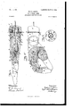
- FIG. 3 is an enlarged top or plan view of an artificial hand embodying my invention with parts thereof broken away, showing a part of the mechanism therein.
- Fig. A is a sectional view of the same on the line w a; in Fig. 3 looking in the direction of the arrow.
- Fig. 5 is asectional view of the same on the line 3 y in Fig. 3 looking in the direction of the arrow.
- Fig. 6 is a transverse section of the same on the line 2 a through the wrist portion in Fig. 4 looking in the direction of the arrow.
- a and A represent portions of an artificial armQand B represents an artificial hand.
- a cord at is shown, which is for the purpose of operating the elbow-joint of the artificial arm.
- a cord Z by means of which the mechanism in the artificial hand is operated.
- This cord 5 may have tension applied thereto in any suitable manner; but I prefer to so secure it to the body of the wearer that tension may be applied to it by a slight movement of the shoulder to which the artificial arm is secured.
- the cord 1) is attached to a link Z), (see Figs. 3 and 4,) which link 6 is pivoted to a lever 6 and which in turn issecured by a pivot b in a chamber in the wrist or body of the hand B, as shown in Fig. 4.
- crank-shaft D is provided with four cranks D, upon which are mounted pitmen Dawhich extend to and are connected with the portions E of the fingers of the artificial hand by means of pivots e, as shown in Fig. 5 and by dotted lines in Fig. 4.
- the portions E of the fingers are pivoted to the body B of the hand by means of pivots 6'.
- pivots c Mounted also upon the pivots c are angle-arms F, one end, f, of which is fixedly secured to the body B of the hand and the other end, f, extending upward in a chamber in the portion E of the fingers. Pivoted to the end f of these angle-arms F in the portions E of the fingers are links f (one of them being shown in Fig. 5,) the opposite ends of these links f being pivoted to the portions G of the fingers by means of pivots g.
- H represents the wrist in the various figures
- B the body of thehand
- E the fingers
- the wrist-joint J is provided with notches j, which are engaged by a spring latch or stop f, by means of which the hand can be adjusted to a required angle and retain ed in that position as long as desired.
- I also provide in the wrist portion a swivel-joint K, which is constructed as follows, viz: Upon the upper end of the wrist portion H, I secure a plate k, having a screw-threaded nipple K upon the central portion thereof, through the central portion ofwhich nipple the chamber 2 extends to'admit of the passage of the link 5 therethrough.
- I secure another plate, L, having a central opening therein of sufficient diameter to admit the screwthreaded nipple K on the plate A to pass therethrough.
- I provide a number of notches or holes Z in the plate L, and in the wrist portion H, I secure a spring-actuated latch or stop h, which passes through an opening in the plate It and enters one of the notches or holes Z in the plate L, thereby holding the hand portion in the desired position.
- Fig. 3,1it will b65861] that portions of a socket, M M, are milled out of the hand portion B at the wristjoint J, which socket-chambers M M are adapted to receive portions N N of the hinge, formed on the wrist portion H, and the wrist portion H is milled out to form portions M M M of a socket, which socket portions are adapted to receive the portions N N N of the hinge on the outside of and between the chambers M M of the socket on the hand portion B, and through all ofithese overlapping hinge portions N N and N N N a pivot m passes to secure the joint from being drawn apart.
- a socket, M M are milled out of the hand portion B at the wristjoint J, which socket-chambers M M are adapted to receive portions N N of the hinge, formed on the wrist portion H, and the wrist portion H is milled out to form portions M M M M of a socket, which socket portions are adapted to receive the portions N N N N of the hinge on the outside of and between
- this pivot m is cut apart or a portion thereof is cut away in thecentral part thereof to admit of the free passage of the link 7) through the wrist-joint.
- the finger and knuckle joints are similar in construction to the wrist-joint, except that there are fewer leaves or laps therein and the pivots therein may be continuous thereth rough. It will readily be seen that this form of joint presents no shoulders or projections upon its outside surface, which is a very desirable feature in artificial hands.
- crank-shaftD has been turned around one-half of a revolution and is held thereby the spring-actuated dog D with the cranks D thereof slightly off of the center in order to maintain a strain upon the dog D which movement has changed the cranks D and pitmen D from the positions thumb and will be tightly compressed therein by the action of the retracting-spring I upon the thumb Land said fingers will be retained in such closed position until tension is again applied to the cord 6 and link 6, which will again move the lever and rack-gear bar 0 as before, and thereby cause the crank-shaft D to complete its revolution, thereby carrying the cranks D and pitmen D back to the position shown by dotted lines in Fig. 4.
- a transverse crankshaft mounted in a chamber in the hand-body, a gear-wheel mounted on said crank-shaft, spring-actuated dog mechanism mounted on said gear-wheel and engaging notches in the periphery of said crank-shaft, a rack-gear bar engaging the gear-Wheel on the crank-shaft, lever-andlink mechanism pivoted to said handbody and to the rack-gear bar, spring mechanism for retaining saidlever-and-link mechanism in a normally forward position, a springactuated dog secured to said hand-body and engaging notches in the periphery of the crank-shaft, pitmen pivoted to the cranks on said crank-shaft at one end and to the fingers of the hand at the other end thereof, substantially as and for the purpose set forth.
Description
4 0 9 1L 7 1 Y A M D E T N E m A P QM E N R A C m W 9m 0 O 6 7 0 N.
ARTIFICIAL LIME.
APPLICATION mum ann'. as, 1903.
2 BHBETSBKEET 1.
I0 IODBL.
all I Ir ve ITIDI', MMQJQMM PATENTED MAY 17, 1904. WJT. GARNES.
ARTIFIGIAL LIMB.
APPLICATION FILED $31 123, 1003.
2 SHEETS-SHEET 3.
N0 MODEL.
Inventor. 204mm .1 am
\X/itqesses. y LU/Wu,
UNITED STATES Patented May 17, 1904.
PATENT OFFICE.
WILLIAM T. (JARNES, OF HARMONSBURG, PENNSYLVANIA, ASSIGNOR OF ONE-FOURTH TO AZRO H. PETTIT, ()F CONNEAUTVILLE, PENNSYLVANIA.
AIYR'TIFICIAL LIMB.
SPECIFICATION forming part of Letters Patent No. 760,102, dated May 1'7, 1904.
Application filed fieptembei 23,1903. Serial No. 174,288. (No model.)
marked thereon, forming part of this specifi cation.
My invention relates'to artificial limbs, and
has for its object the construction of an artificial hand provided with mechanism so constructed and combined that the fingers of the hand can be operated either with or without the assistance of the wearers other hand and wlth the oints of the wrist and fingers so made that they present no shoulders or corners visible through a glove worn on said hand and also with a wrist-joint so adjustable that it can be rotated on its axis and be securedat any desired point to which it may be rotated. These and other features of my invention are hereinafter set forth and described, and illustrated in the accompanying drawings, in which- Figure 1 is a top or plan view of an artificial arm and a hand embodying my invention. Fig. 2 is a side view of the same. Fig. 3 is an enlarged top or plan view of an artificial hand embodying my invention with parts thereof broken away, showing a part of the mechanism therein. Fig. A is a sectional view of the same on the line w a; in Fig. 3 looking in the direction of the arrow. Fig. 5 is asectional view of the same on the line 3 y in Fig. 3 looking in the direction of the arrow. Fig. 6 is a transverse section of the same on the line 2 a through the wrist portion in Fig. 4 looking in the direction of the arrow.
In the drawings, A and A represent portions of an artificial armQand B represents an artificial hand. In Figs, 1 and 2 a cord at is shown, which is for the purpose of operating the elbow-joint of the artificial arm. There is also a cord Z), by means of which the mechanism in the artificial hand is operated. This cord 5 may have tension applied thereto in any suitable manner; but I prefer to so secure it to the body of the wearer that tension may be applied to it by a slight movement of the shoulder to which the artificial arm is secured. The cord 1) is attached to a link Z), (see Figs. 3 and 4,) which link 6 is pivoted to a lever 6 and which in turn issecured by a pivot b in a chamber in the wrist or body of the hand B, as shown in Fig. 4. For retaining the lever Z) in a. normally forward position I provide a retracting-spring 6*. To the free end of the lever Zr is pivoted a rack-gear bar C, the teeth 0 of which inter-mesh with a segment of gearteeth 0, embracing the transverse crank-shaft D. This segmental gear 0 is provided with a spring-actuated dog 0, adapted to engage notches (id, cut in the crank-shaft D. Secured in the body of the band B there is also a springactuated dog D, adapted to engage notches d (see Fig. 3) on the crank-shaft I) on the opposite side of the segmental gear 0, so as to'prevent any backward rotation of the shaft D, these notches (17/ being so placed on the periphery of the crank-shaft D as to retain the cranks thereon slightly oil of the center of the shaft, thereby causing a strain to he kept at all times upon the dog D when the shaft is not in a state of rotation. The crank-shaft D is provided with four cranks D, upon which are mounted pitmen Dawhich extend to and are connected with the portions E of the fingers of the artificial hand by means of pivots e, as shown in Fig. 5 and by dotted lines in Fig. 4. The portions E of the fingers are pivoted to the body B of the hand by means of pivots 6'. (See Fig. 5.). Mounted also upon the pivots c are angle-arms F, one end, f, of which is fixedly secured to the body B of the hand and the other end, f, extending upward in a chamber in the portion E of the fingers. Pivoted to the end f of these angle-arms F in the portions E of the fingers are links f (one of them being shown in Fig. 5,) the opposite ends of these links f being pivoted to the portions G of the fingers by means of pivots g.
H represents the wrist in the various figures, B the body of thehand, and E the fingers,
and the finger portion G at 14: are cham- I bered out to receive the mechanism hereinbefore described and to allow of the free and unobstructed operation thereof.
To the body portion B of the hand there is pivoted a thumb I by means of the pivot 2 the inner end of this thumb being chambered out at'15 to allow space for the operation of a retracting-spring I, and the body B of the hand is also chambered out at 16 for the reception and operation of the spring I.
The wrist-joint J is provided with notches j, which are engaged by a spring latch or stop f, by means of which the hand can be adjusted to a required angle and retain ed in that position as long as desired. I also provide in the wrist portion a swivel-joint K, which is constructed as follows, viz: Upon the upper end of the wrist portion H, I secure a plate k, having a screw-threaded nipple K upon the central portion thereof, through the central portion ofwhich nipple the chamber 2 extends to'admit of the passage of the link 5 therethrough. Upon the portion A of the artificial arm which in order to secure lightness is made hollow, as at A in Fig. 4, I secure another plate, L, having a central opening therein of sufficient diameter to admit the screwthreaded nipple K on the plate A to pass therethrough. Upon the screw-threaded end of the nipple K extending'through the hole in the plate L, I secure an internally-screwthreaded collar K which holds the nipple K within the opening in the plate L and the plate is, with the wrist portion H securedthereto firmly against the plate L, but permits of the free rotationof the same upon the nipple in the arm portion A. To secure the artificial hand at the desired point of rotation, I provide a number of notches or holes Z in the plate L, and in the wrist portion H, I secure a spring-actuated latch or stop h, which passes through an opening in the plate It and enters one of the notches or holes Z in the plate L, thereby holding the hand portion in the desired position. U
I I also desire to call attention to the construction of the wrist and finger joints of my improved artificial hand, which are of hingedsocket form, as shown in full and dotted lines in Figs. 3, 4, and 5. Referring to Fig. 3,1it will b65861] that portions of a socket, M M, are milled out of the hand portion B at the wristjoint J, which socket-chambers M M are adapted to receive portions N N of the hinge, formed on the wrist portion H, and the wrist portion H is milled out to form portions M M M of a socket, which socket portions are adapted to receive the portions N N N of the hinge on the outside of and between the chambers M M of the socket on the hand portion B, and through all ofithese overlapping hinge portions N N and N N N a pivot m passes to secure the joint from being drawn apart. In
the wrist-joint this pivot m is cut apart or a portion thereof is cut away in thecentral part thereof to admit of the free passage of the link 7) through the wrist-joint. The finger and knuckle joints are similar in construction to the wrist-joint, except that there are fewer leaves or laps therein and the pivots therein may be continuous thereth rough. It will readily be seen that this form of joint presents no shoulders or projections upon its outside surface, which is a very desirable feature in artificial hands.
In operation when it is desired to close the fingers of the hand the wearer causes tension to be applied to the cord 6 and link 6 ordinarily by a movement of the shoulder to which the artificial arm'is secured, which draws the lever b and rack-gear bar C, secured thereto, back into the .position shown by dotted lines in Fig.4. This movement of the rack-gear bar G causes the segmental gear 0 to turn, and the spring-actuated dog 0 thereon engaging one of the notches (Z in the crank-shaft D carries the crank-shaft D around one-half of a revolution, at which point the s pring-actuated dog D engages one of the notches d in the crank-shaft D on the side of the segmental gear opposite the spring-dog 0 and holds it from turning backward when the tension 18 removed from the cord 6 and link 7),when the retracting-spring 71 in the chamber 4 causes the lever b and rack-gear bar C and segmental gear 0 to return to their normal positions. (Shown in full lines in Fig. 4.) The crank-shaftD, however, has been turned around one-half of a revolution and is held thereby the spring-actuated dog D with the cranks D thereof slightly off of the center in order to maintain a strain upon the dog D which movement has changed the cranks D and pitmen D from the positions thumb and will be tightly compressed therein by the action of the retracting-spring I upon the thumb Land said fingers will be retained in such closed position until tension is again applied to the cord 6 and link 6, which will again move the lever and rack-gear bar 0 as before, and thereby cause the crank-shaft D to complete its revolution, thereby carrying the cranks D and pitmen D back to the position shown by dotted lines in Fig. 4.
Having thus fully described my invention, so as to enable others skilled in the art to construct and utilize the same, what I claim as new, and desire to secure by Letters Patent of hinged joints intermediate of the elbow-joint and the artificial hand, fingers hinged thereto, mechanism in said artificial hand adapted to open and close the fingers thereof, a thumb member pivoted to the hand-body, and means for yieldingly holding said thumb member in a normally closed position in opposition to the fingers, substantially as and for the pur pose set forth.
2. The combination in an artificial hand, of
fingers hinged thereto, a transverse crankshaft mounted in a chamber in the hand-body, a gear-wheel mounted on said crank-shaft, spring-actuated dog mechanism mounted on said gear-wheel and engaging notches in the periphery of said crank-shaft, a rack-gear bar engaging the gear-Wheel on the crank-shaft, lever-andlink mechanism pivoted to said handbody and to the rack-gear bar, spring mechanism for retaining saidlever-and-link mechanism in a normally forward position, a springactuated dog secured to said hand-body and engaging notches in the periphery of the crank-shaft, pitmen pivoted to the cranks on said crank-shaft at one end and to the fingers of the hand at the other end thereof, substantially as and for the purpose set forth.
3. The combination in an artificial hand, of a transverse crank-shaft in the hand-body, mechanism adapted to rotate said crank-shaft a half-revolution, spring mechanism for retaining said mechanism in a normally outward position, pitmen connecting the cranks on said crank-shaft with the lower portions of the knuckle-joints of the fingers on said hand, angle-arms mounted on the pivots of said knuckle-joints one end thereof being secured in the hand-body, links attached to the opposite ends of said angle-arms and to the lower part of the middle joints of the fingers, substantially as and for the purpose set forth.
4:. In an artificial arm and hand, the combination of a swivel-joint in one part of the wrist portion, latch or stop mechanism adapted to secure said swivel-joint in a position desired, a hinged socket-joint in the wrist portion of said artificial hand below said swiveljoint, latch or stop mechanism for retaining said hinged socket-joint in a desired position, a hand-body, mechanism therein for opening and closing the fingers of said hand, fingers pivoted to said hand-body by means of hinged socket-joints, and means for connecting the actuating mechanism of the fingers with the body of the wearer whereby the same may be operated, substantially as and for the purpose set forth.
In testimony whereof I aflix my signature in presence of two witnesses.
WILLIAM T. GARNES.
Witnesses:
H. M. STURGEON, F. J. BASSETT.
Priority Applications (1)
| Application Number | Priority Date | Filing Date | Title |
|---|---|---|---|
| US17428803A US760102A (en) | 1903-09-23 | 1903-09-23 | Artificial limb. |
Applications Claiming Priority (1)
| Application Number | Priority Date | Filing Date | Title |
|---|---|---|---|
| US17428803A US760102A (en) | 1903-09-23 | 1903-09-23 | Artificial limb. |
Publications (1)
| Publication Number | Publication Date |
|---|---|
| US760102A true US760102A (en) | 1904-05-17 |
Family
ID=2828591
Family Applications (1)
| Application Number | Title | Priority Date | Filing Date |
|---|---|---|---|
| US17428803A Expired - Lifetime US760102A (en) | 1903-09-23 | 1903-09-23 | Artificial limb. |
Country Status (1)
| Country | Link |
|---|---|
| US (1) | US760102A (en) |
Cited By (9)
| Publication number | Priority date | Publication date | Assignee | Title |
|---|---|---|---|---|
| US2553827A (en) * | 1948-10-27 | 1951-05-22 | Northrop Aircraft Inc | Artificial hand with articulated fingers and passively positioned thumb |
| US2582234A (en) * | 1948-06-28 | 1952-01-15 | Jr John E Conzelman | Prosthetic hand |
| US2692390A (en) * | 1952-10-22 | 1954-10-19 | Northrop Aircraft Inc | Wrist flexion unit |
| US2834024A (en) * | 1954-09-10 | 1958-05-13 | Joseph C Aveni | Artificial arm |
| US10973660B2 (en) | 2017-12-15 | 2021-04-13 | Touch Bionics Limited | Powered prosthetic thumb |
| US11083600B2 (en) | 2014-02-25 | 2021-08-10 | Touch Bionics Limited | Prosthetic digit for use with touchscreen devices |
| US11357646B2 (en) | 2014-10-03 | 2022-06-14 | Touch Bionics Limited | Wrist device for a prosthetic limb |
| US11464654B2 (en) | 2014-02-04 | 2022-10-11 | Rehabilitation Institute Of Chicago | Modular and lightweight myoelectric prosthesis components and related methods |
| US11931270B2 (en) | 2019-11-15 | 2024-03-19 | Touch Bionics Limited | Prosthetic digit actuator |
-
1903
- 1903-09-23 US US17428803A patent/US760102A/en not_active Expired - Lifetime
Cited By (10)
| Publication number | Priority date | Publication date | Assignee | Title |
|---|---|---|---|---|
| US2582234A (en) * | 1948-06-28 | 1952-01-15 | Jr John E Conzelman | Prosthetic hand |
| US2553827A (en) * | 1948-10-27 | 1951-05-22 | Northrop Aircraft Inc | Artificial hand with articulated fingers and passively positioned thumb |
| US2692390A (en) * | 1952-10-22 | 1954-10-19 | Northrop Aircraft Inc | Wrist flexion unit |
| US2834024A (en) * | 1954-09-10 | 1958-05-13 | Joseph C Aveni | Artificial arm |
| US11464654B2 (en) | 2014-02-04 | 2022-10-11 | Rehabilitation Institute Of Chicago | Modular and lightweight myoelectric prosthesis components and related methods |
| US11083600B2 (en) | 2014-02-25 | 2021-08-10 | Touch Bionics Limited | Prosthetic digit for use with touchscreen devices |
| US11357646B2 (en) | 2014-10-03 | 2022-06-14 | Touch Bionics Limited | Wrist device for a prosthetic limb |
| US10973660B2 (en) | 2017-12-15 | 2021-04-13 | Touch Bionics Limited | Powered prosthetic thumb |
| US11786381B2 (en) | 2017-12-15 | 2023-10-17 | Touch Bionics Limited | Powered prosthetic thumb |
| US11931270B2 (en) | 2019-11-15 | 2024-03-19 | Touch Bionics Limited | Prosthetic digit actuator |
Similar Documents
| Publication | Publication Date | Title |
|---|---|---|
| US760102A (en) | Artificial limb. | |
| JP5074414B2 (en) | Prosthetic hand | |
| AU2015257679B2 (en) | Actuation of a hand to be provided on a humanoid robot | |
| DE602006006668D1 (en) | FLEXIBLE CONNECTION | |
| US1298502A (en) | Artificial hand. | |
| US999484A (en) | Artificial arm and hand. | |
| US319776A (en) | Tebeitoby | |
| US2464577A (en) | Actuating mechanism for artificial hands | |
| US51238A (en) | Improvement in artificial arms | |
| US1285617A (en) | Artificial hand. | |
| US2382404A (en) | Artificial hand and means for actuating the same | |
| US1305169A (en) | rohrmann | |
| US42515A (en) | Improvement in artificial arms | |
| US1319884A (en) | Punooearm | |
| US628239A (en) | Hinge-joint for flat articles. | |
| US57594A (en) | Improvement in artificial arms | |
| US18266A (en) | Wrench | |
| US45876A (en) | Improvement in artificial arms | |
| JPS59182093A (en) | Manipulator | |
| US206184A (en) | Improvement in mechanical movements | |
| US18021A (en) | William selpho | |
| US429243A (en) | Artificial hand | |
| US50014A (en) | Improvement in artificial hands | |
| US879360A (en) | Artificial hand. | |
| US255796A (en) | Executrix of |