US7597381B2 - Recreational vehicle mat device - Google Patents
Recreational vehicle mat device Download PDFInfo
- Publication number
- US7597381B2 US7597381B2 US12/074,074 US7407408A US7597381B2 US 7597381 B2 US7597381 B2 US 7597381B2 US 7407408 A US7407408 A US 7407408A US 7597381 B2 US7597381 B2 US 7597381B2
- Authority
- US
- United States
- Prior art keywords
- mat
- roller unit
- coupled
- storage unit
- unit
- Prior art date
- Legal status (The legal status is an assumption and is not a legal conclusion. Google has not performed a legal analysis and makes no representation as to the accuracy of the status listed.)
- Active - Reinstated, expires
Links
- 230000007246 mechanism Effects 0.000 claims description 22
- 238000000034 method Methods 0.000 claims description 18
- 230000008878 coupling Effects 0.000 claims description 12
- 238000010168 coupling process Methods 0.000 claims description 12
- 238000005859 coupling reaction Methods 0.000 claims description 12
- 230000001680 brushing effect Effects 0.000 claims description 9
- 238000005096 rolling process Methods 0.000 claims description 4
- 239000000463 material Substances 0.000 description 18
- 239000004033 plastic Substances 0.000 description 4
- 229910000831 Steel Inorganic materials 0.000 description 3
- 229910052782 aluminium Inorganic materials 0.000 description 3
- XAGFODPZIPBFFR-UHFFFAOYSA-N aluminium Chemical compound [Al] XAGFODPZIPBFFR-UHFFFAOYSA-N 0.000 description 3
- 239000010959 steel Substances 0.000 description 3
- 239000011152 fibreglass Substances 0.000 description 2
- 229910052751 metal Inorganic materials 0.000 description 2
- 239000002184 metal Substances 0.000 description 2
- 229920003023 plastic Polymers 0.000 description 2
- 230000008439 repair process Effects 0.000 description 2
- 125000000391 vinyl group Chemical group [H]C([*])=C([H])[H] 0.000 description 2
- 229920002554 vinyl polymer Polymers 0.000 description 2
- 230000008901 benefit Effects 0.000 description 1
- 238000004140 cleaning Methods 0.000 description 1
- 239000004744 fabric Substances 0.000 description 1
- 238000012423 maintenance Methods 0.000 description 1
- -1 mesh Polymers 0.000 description 1
- 239000002905 metal composite material Substances 0.000 description 1
- 239000007769 metal material Substances 0.000 description 1
- 150000002739 metals Chemical class 0.000 description 1
- 238000012986 modification Methods 0.000 description 1
- 230000004048 modification Effects 0.000 description 1
- 230000000717 retained effect Effects 0.000 description 1
- 239000004576 sand Substances 0.000 description 1
- 239000002023 wood Substances 0.000 description 1
Images


Classifications
-
- B—PERFORMING OPERATIONS; TRANSPORTING
- B60—VEHICLES IN GENERAL
- B60P—VEHICLES ADAPTED FOR LOAD TRANSPORTATION OR TO TRANSPORT, TO CARRY, OR TO COMPRISE SPECIAL LOADS OR OBJECTS
- B60P3/00—Vehicles adapted to transport, to carry or to comprise special loads or objects
- B60P3/32—Vehicles adapted to transport, to carry or to comprise special loads or objects comprising living accommodation for people, e.g. caravans, camping, or like vehicles
- B60P3/36—Auxiliary arrangements; Arrangements of living accommodation; Details
Definitions
- RV recreational vehicle
- RVs are convenient because the traveler brings their home with them on vacation.
- Many RVs have all the comforts of home.
- the majority of RV enthusiasts utilize the area surrounding their parked RV for living space as well.
- the disclosure is directed a mat device for a recreational vehicle.
- the mat device comprises a mat configured to be utilized on a ground surface near the recreational vehicle.
- the mat device includes a roller unit having a rotatable bar disposed between a first end opposite a second end.
- the rotatable bar is coupled to a first caster device at the first end and to a second caster device at the second end.
- the mat is configured to couple to and to roll upon the rotatable bar.
- the mat device includes a storage unit having a top wall opposite a bottom wall, a first side wall opposite a second side wall, and a cap opposite a back wall with a track coupled to an interior of the storage device.
- the track is configured to receive the first caster device and the second caster device of the roller unit.
- the storage unit is located on the recreational vehicle.
- a method of using a mat device for a recreational vehicle comprises opening a cap of a storage unit, such that the storage unit comprises a top wall opposite a bottom wall, a first side wall opposite a second side wall.
- the cap is opposite a back wall with a track coupled to an interior of the storage device.
- the track is configured to receive the roller unit.
- the storage unit is located on the recreational vehicle.
- the method comprises pulling a roller unit from storage unit.
- the roller unit has a rotatable bar disposed between a first end opposite a second end.
- the rotatable bar is coupled to a first caster device at the first end and to a second caster device at the second end.
- a mat is coupled to and rolled upon the rotatable bar.
- the roller unit can move along the track and fully extend from the storage unit.
- the method comprises coupling at least one support to the first end of the roller unit, such that the support stands on a ground surface.
- the method includes removing at least one strap coupled to itself from the mat rolled upon the roller unit.
- the method comprises grasping a handle coupled to a first end of the mat and pulling the handle to unravel the mat from the roller unit.
- the method includes uncoupling receiving mechanisms of the weighted bar disposed on a first end of the mat from hooking mechanisms disposed on the rotatable bar and positioning the mat on the ground surface.
- the method comprises extending a roller unit from a storage unit disposed on a recreational vehicle.
- the roller unit has a rotatable bar disposed between a first end opposite a second end.
- the rotatable bar is coupled to a first caster device at the first end and to a second caster device at the second end.
- a mat is coupled to and rolled upon the rotatable bar.
- the roller unit moves along a track disposed in an interior of the storage unit.
- the method includes coupling at least one support to the first end of the roller unit, such that the support stands on a ground surface.
- the method comprises coupling receivers disposed on a weighted bar coupled to a second end of the mat to hooking mechanisms disposed on the rotatable bar.
- the method includes rotating the rotatable bar of the roller unit and rolling the mat upon the rotatable bar of the roller unit.
- the method comprises coupling at least one strap around the mat rolled upon the roller unit to itself, removing the support from the roller unit, and pushing the roller unit into the storage unit, such that the roller unit slides along the track and into the storage unit.
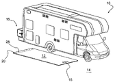
- FIG. 1 is a perspective view of a recreational vehicle and an exemplary embodiment of the recreational vehicle mat device
- FIG. 2 is a side view of an exemplary embodiment of the recreational vehicle mat device extending from the recreational vehicle;
- FIG. 3 is a side view of a recreational vehicle
- FIG. 4 is another side view of a recreational vehicle
- FIG. 5 is a side view of a storage unit
- FIG. 6 is a side view of a roller unit
- FIG. 7 is a another side view of a roller unit
- FIG. 8 is a side view of the roller unit comprising a brushing device
- FIG. 8A is a front view of the roller unit comprising a brushing device
- FIG. 9 is a side view of a mat disposed upon a roller unit
- FIG. 10 is a side view of a storage unit
- FIG. 11 is another side view of a storage unit.
- the present disclosure is a portable mat for a recreational vehicle (RV).
- the mat can be positioned near the RV to provide additional living space.
- the mat can be stored in a storage unit located on the RV, for example, in an external mount fixed to the bumper (or frame) or in a rear storage compartment of the RV.
- the mat can be coupled to a roller unit that telescopes from the RV. Once extended and supported, the mat can be unrolled from the roller and released to the ground. The roller can then be retracted into the RV for storage.
- the mat is physically coupled to the roller unit. When finished using the mat, the user can reattach the mat to the roller unit and roll the mat over the roller unit. The telescoping roller unit can then be retracted back into the storage unit of the RV.
- the present disclosure provides a device that allows an RV mat to be easily accessible and easily maintained by the RV user.
- FIG. 1 illustrates a perspective view of a conventional RV 10 having a mat 12 disposed on the ground 14 near the RV 10 .
- the mat 12 has been unrolled from the storage unit 16 and positioned on the ground 14 .
- the mat 12 comprises at least one handle 18 and a weighted bar 20 .
- the roller unit 22 extending from the storage unit 16 is illustrated.
- the storage unit 16 is coupled to the bumper 24 of the RV 10 .
- the mat 12 can be unrolled from the storage unit 16 utilizing the handle 18 to pull the mat 12 from the roller unit 22 .
- a weighted bar 20 is coupled to one end of the mat 12 for ease in coupling the mat 12 to the roller unit 22 .
- the weighted bar 20 has connection points 26 that correspond to hooking mechanisms 28 on the roller unit 22 (illustrated in FIG. 6 ) for coupling the mat 12 to the roller unit 22 .
- the weighted bar 20 can be easily coupled to any type of mat 12 desired by the user.
- the weighted bar 20 also serves to keep the mat 12 firmly positioned on the ground 14 .
- the handle 18 can be disposed in the material of the mat 12 or it can be coupled to another weighted bar 30 for ease in attaching the handle 18 to any desired mat material.
- FIG. 2 illustrates the mat 12 rolled upon the roller unit 22 .
- Supports 32 are utilized to support the weight of the mat 12 and roller unit 22 when extended from the storage unit 16 .
- the supports 32 will be discussed further herein.
- a crank handle 34 can be utilized to roll and unroll the mat 12 from the roller unit 22 .
- the crank handle 34 will be discussed further herein.
- a mat 12 that comprises a carpet material, rubber material, vinyl material, mesh material, turf material, heavy cloth material and the like.
- the mat 12 can be personalized with words, team or sport logos, patterns, designs, and the like. It is also contemplated that written greetings can be disposed on the mat 12 .
- the mat 12 can be any desired length that can fit into the interior of the storage unit 16 when completely rolled up. It is contemplated that the width of the mat 12 is smaller than the width of a typical RV (i.e., about 7 to about 8 feet). The width of the mat 12 must also fit into the interior of the storage unit 16 . A preferred maximum dimension of the mat 12 is about 10 feet to about 25 feet in length by about 7 feet in width.
- the storage unit 16 is externally mounted on the rear bumper 24 of the RV 10 .
- Other embodiments of storage unit 16 are also contemplated.
- the storage unit 16 can be stored in a rear storage compartment 36 of an RV 10 (see FIG. 3 ) utilizing the interior mechanisms of the storage unit 16 discussed herein or the storage unit 16 can be mounted onto the RV 10 frame 38 (see FIG. 4 ).
- the storage unit 16 is configured to completely contain the roller unit 22 and mat 12 .
- the storage unit 16 has two side walls 40 , 42 , a top 44 , a bottom 46 , an end 48 and a cap 50 .
- the bottom 46 is coupled to the bumper 24 with bolts, brackets, and the like.
- the cap 50 is removable (or hinged) so that the roller unit 22 can be inserted into the storage unit 16 , as will be discussed further herein.
- a locking mechanism 52 can be utilized to secure the cap 50 to the storage unit 16 .
- Preferred locking mechanisms include cotter pins, latches, pins, bolts, locks, and the like.
- the top 44 is also removable or hinged for ease in accessing the interior 54 of the storage unit 16 to repair or maintain the sliding mechanism 56 , as will be discussed further herein.
- the side walls 40 , 42 can also be removable or hinged for ease in accessing the interior 54 of the storage unit 16 to repair or maintain the sliding mechanism 56 .
- the storage unit 16 can be comprised of any durable material that can withstand wind, weather, and flying debris, such as aluminum, steel, plastic, wood, fiberglass, and the like.
- the length of the storage unit 16 is less than the width of the RV 10 .
- a preferred maximum dimension of the storage unit 16 is about six feet to about eight feet in length by about six inches to about 8 inches in width with a height of about six inches to about eight inches.
- the roller unit 22 comprises a bar 58 having a first end 60 opposite a second end 62 .
- the bar 58 is pivotally coupled to a first bracket 64 at the first end 60 and to a second bracket 66 at the second end 62 .
- a first caster 68 is coupled to the top of the first bracket 64 and a second caster 70 is coupled to the top of the second bracket 66 .
- the first caster 68 and the second caster 70 are configured to slidingly couple to a sliding mechanism (or track) 56 , 72 disposed in the interior 54 of the storage unit 16 .
- the first caster 68 and the second caster 70 matingly couple with the track 72 to slide the roller unit 22 comprising the mat 12 in and out of the storage unit 16 .
- a user of the RV mat device grasps the end of the roller unit 22 and pulls the roller unit 22 from the storage unit 16 .
- a handle (not shown) can be coupled to the first end 60 of the roller unit 22 for ease in pulling and pushing the roller unit 22 out of and into the storage unit 16 .
- Other embodiments contemplate the use of a pulley system or a spring loaded mechanism for removing the roller unit 22 from the storage unit 16 .
- the length of the roller unit 22 is less than the width of the RV 10 .
- a preferred maximum dimension of the roller unit 22 is about six to about seven feet in length by about 1 inch to about 4 inches in diameter.
- the bar 58 can comprise any material that can support the weight of the rolled up mat 12 . Preferred materials include aluminum, steel, plastic, wood, wire cable, and the like.
- a preferred maximum dimension of the bar 58 is about seven feet in length by about one inch in width.
- FIG. 7 illustrates a side view of the interior 54 of the storage unit 16 .
- the track 72 is disposed on the top 44 of the storage unit 16 .
- the first caster 68 and second caster 70 are configured to slide along the track 72 horizontally, as illustrated with arrows 72 , 74 , in order to have the roller unit 22 extend out from the storage unit 16 .
- the second caster 70 is configured to support the weight of the extending roller unit 22 and to be retained by the track 72 , when the roller unit 22 is fully extended from the storage unit 16 .
- the first caster 68 and second caster 70 can be coupled to a sliding bracket unit (not shown) that also extends from the track 72 to protect the casters 68 , 70 .
- the track 72 is located in the interior 54 of the storage unit 16 .
- the track 72 is preferably coupled to the top 44 , as illustrated in FIG. 7 , in order to prevent dirt, sand, and debris from clogging or obstructing the operation of the track 72 .
- the track 72 can be disposed in the interior 54 of the storage unit 16 on any of the interior walls of the side walls 40 , 42 , or bottom 46 .
- the track 72 can be any conventional track that is configured to retain a caster 68 , 70 (coupled to the roller unit 22 ) from exiting the track 72 while allowing at least one caster 68 , 70 to slide along the track 72 .
- the track 72 can be configured to allow the caster 68 , 70 to exit the track 72 at an end to allow the roller unit 22 to telescope from the storage unit 16 .
- the track is preferably a material sturdy enough to support the weight of the roller unit 22 , including but not limited to, metals, such as steel, aluminum, metal composites, fiberglass, wood, and the like, as well as durable plastics. It is also contemplated that metal tracks can be fitted with ball bearings to allow for the roller unit 22 to easily glide and telescope out of the storage unit 16 .
- the supports 24 can be coupled to the first end 60 of the bar 58 to support the weight of the roller unit 22 on the ground 14 .
- the first bracket 64 is configured with a connection mechanism 76 for coupling the supports 32 to the roller unit 22 .
- the crank handle 34 can be coupled to the first end 60 of the bar 58 for rotating the bar 58 in order to roll up the mat 12 onto the bar 58 .
- a motor 90 can be coupled to the first end 60 of the bar 58 to automatically roll up the mat 12 , as illustrated in FIG. 9 .
- a preferred motor 90 can be an awning retracting motor.
- the supports 32 can be any support that is configured to be stable on the ground 14 and to support the weight of the roller unit 22 . It is contemplated that the supports 32 resemble conventional legs.
- the supports 32 comprise a sturdy and durable material that can support the weight of the roller unit 22 .
- the crank handle 34 can be any conventional handle that is durable and easily attached to the connection mechanism 76 .
- FIGS. 8 and 8A a side view of the first end 60 of the roller unit 22 is illustrated. Coupled to each end 60 , 62 and extending the length of the roller unit 22 is a brushing device 78 .
- the brushing device 78 has spring loaded arms 80 coupled to the first bracket 64 and second bracket 66 of the roller unit 22 and extends outward from the roller unit 22 . Coupled to the end of the arms 80 are brushes 82 utilized for cleaning the mat 12 .
- the mat 12 is fed through the opening 84 between the brushes 82 and physically interacts with the brushes 82 .
- the brushes 82 remove dirt and debris from the mat 12 as it is being rolled upon or removed from the roller unit 22 .
- spring loaded arms 80 are described herein, any mechanism that can support the weight of the brushes interacting with the mat can be utilized.
- the mat 12 When the mat 12 is rolled upon the roller unit 22 , the mat can be secured onto the roller unit 22 with straps (or ties) 86 .
- the straps 86 can be comprised of any material that is durable enough to retain the rolled mat 12 . Preferred materials include vinyl, mesh, rubber, and the like.
- the straps 86 can be tied or hooked together with eye hooks, hook and loop fasteners, snaps, or other conventional hooking mechanisms.
- the weighted bar 20 is coupled to the end of mat 12 and provides a mechanism for attaching the mat 12 to the roller unit 22 .
- the weighted bar 20 also serves to weight down the mat 12 for holding the mat 12 in place on the ground 14 .
- the weighted bar 20 is preferably a material that is durable, including but not limited to, a heavy rubber material, a light weight metal material, plastic, and the like.
- the weighted bar 20 can be a single item extending the length of the mat as illustrated in FIG. 1 or the weighted bar 20 can be several separate pieces coupled to the mat 12 . It is contemplated that the weighted bar 20 can be attached to the mat 12 or can be easily installed on to any mat 12 desired by the user.
- casters (or rollers) 88 can be installed in the interior 54 of the storage unit 16 . It is contemplated to have two or more casters 88 to cradle the end 62 of the roller unit 22 in order to give the roller unit 22 support while moving in and out of the storage unit 16 .
- the casters 88 can also act to stabilize the roller unit 22 when completely stored away and when the RV 10 is being operated. It is also contemplated to have several casters 88 disposed in the interior 56 of the storage unit 16 to support the roller unit 22 .
- the user can easily retrieve the mat 12 from the storage unit 16 .
- the user removes the cap 50 from the storage unit 16 .
- the user grasps the end 60 of the roller unit 22 , preferably a handle (not illustrated).
- the user pulls the roller unit 22 from the storage unit 16 , such that the mat 12 rolled upon the roller unit 22 extends perpendicularly from the RV 10 .
- Casters 88 coupled to the storage unit 16 guide and support the mat 12 .
- the supports 32 are coupled to the end 60 of the roller unit 22 to support the weight of the mat 12 .
- the user removes the straps 86 from the mat 12 and grasps the handle 18 .
- the user completely unrolls the mat 12 from the roller unit 22 and places the handle 18 end on the ground 14 .
- the user then removes the weighted bar 20 from the roller unit 22 and places it on the ground 14 .
- the user can then remove the supports 32 and slide the roller unit 22 back into the storage unit 16 for storage.
- the user When the user is finished with the mat 12 , the user simply extends the roller unit 22 from the storage unit 16 and places the supports 32 on the end 60 .
- the weighted bar 20 of the mat 12 is coupled to the roller unit 22 via the hooking mechanisms 26 .
- a crank handle 32 can be utilized to roll the mat 12 onto the roller unit 22 .
- a motor 90 can be utilized to automatically retract the mat 12 onto the roller unit 22 .
- a brushing device 78 coupled along the length of the roller unit 22 , brushes debris off both sides of the mat 12 .
- the user secures the mat 12 with the straps 86 .
- the user removes and separately stores the supports 32 .
- the user can then push the roller unit 22 , such that the roller unit 22 rolls along the casters 88 into the storage unit 16 .
- the user then replaces the cap 50 and drives away.
- the present disclosure is a portable mat for a recreational vehicle (RV) for extending living space.
- the mat is conveniently stored in a storage unit located on the RV and easily removed via a roller unit that extends from the storage unit. Once extended and supported, the mat can be unrolled from the roller and released to the ground. The user can easily reattach the mat to the roller unit and roll the mat over the roller unit.
- the present disclosure provides a device that allows an RV mat to be easily accessible, readily unrolled and re-rolled, and easily maintained by the RV user.
Landscapes
- Engineering & Computer Science (AREA)
- Health & Medical Sciences (AREA)
- Public Health (AREA)
- Transportation (AREA)
- Mechanical Engineering (AREA)
- Handcart (AREA)
Abstract
Description
Claims (20)
Priority Applications (1)
| Application Number | Priority Date | Filing Date | Title |
|---|---|---|---|
| US12/074,074 US7597381B2 (en) | 2008-02-28 | 2008-02-28 | Recreational vehicle mat device |
Applications Claiming Priority (1)
| Application Number | Priority Date | Filing Date | Title |
|---|---|---|---|
| US12/074,074 US7597381B2 (en) | 2008-02-28 | 2008-02-28 | Recreational vehicle mat device |
Publications (2)
| Publication Number | Publication Date |
|---|---|
| US20090218847A1 US20090218847A1 (en) | 2009-09-03 |
| US7597381B2 true US7597381B2 (en) | 2009-10-06 |
Family
ID=41012618
Family Applications (1)
| Application Number | Title | Priority Date | Filing Date |
|---|---|---|---|
| US12/074,074 Active - Reinstated 2028-03-21 US7597381B2 (en) | 2008-02-28 | 2008-02-28 | Recreational vehicle mat device |
Country Status (1)
| Country | Link |
|---|---|
| US (1) | US7597381B2 (en) |
Cited By (5)
| Publication number | Priority date | Publication date | Assignee | Title |
|---|---|---|---|---|
| US20090248546A1 (en) * | 2008-01-18 | 2009-10-01 | Jon Norris | Marketing System And Method |
| US10053329B2 (en) * | 2015-07-28 | 2018-08-21 | Janice V Wilcoxon | Automated aisle runner |
| US20180244141A1 (en) * | 2015-08-28 | 2018-08-30 | Girard Guard, Llc | Retractable tire awnings and related methods |
| US10426260B2 (en) * | 2013-07-19 | 2019-10-01 | The Texas A&M University System | Adjustable height desk having a deployable floor mat |
| US10597253B2 (en) * | 2015-07-28 | 2020-03-24 | Janice Voncille Wilcoxon | Automated aisle runner |
Families Citing this family (1)
| Publication number | Priority date | Publication date | Assignee | Title |
|---|---|---|---|---|
| US10982450B2 (en) * | 2017-05-24 | 2021-04-20 | Charlie Burnside | Retractable floor cover |
Citations (12)
| Publication number | Priority date | Publication date | Assignee | Title |
|---|---|---|---|---|
| US1719055A (en) | 1927-04-20 | 1929-07-02 | John H Herzer | Combination bumper, container, tent, and car cover |
| US2723156A (en) | 1953-02-26 | 1955-11-08 | Stanziale Victor | Self positioning auto cover |
| US3021894A (en) | 1959-04-13 | 1962-02-20 | Due George F La | Car top protective cover |
| US3563594A (en) | 1969-05-02 | 1971-02-16 | Arnold B London | Retractable flexible car body protector |
| US4109954A (en) | 1976-11-24 | 1978-08-29 | Wall Richard E | Expandable camper apparatus |
| US4195875A (en) | 1978-05-15 | 1980-04-01 | Venne Phillip L | Portable entranceway carpet for a recreational vehicle |
| US4413855A (en) | 1981-07-15 | 1983-11-08 | Francis Flanagan | Sliding patio for travel trailers and mobile homes |
| US4706991A (en) | 1985-11-25 | 1987-11-17 | Miller Mahlon A | Trailer front stone guard |
| US4991789A (en) | 1989-10-16 | 1991-02-12 | Buerger Michael H | Retractable carpet system for vehicular quarters |
| US6260909B1 (en) | 1998-03-19 | 2001-07-17 | Alfa Leisure, Inc. | Awning and rug assembly for a trailer |
| US20060145514A1 (en) | 2005-01-04 | 2006-07-06 | Cardwell Randy C | Retractable patio assembly for a recreational vehicle |
| US20070187989A1 (en) | 2006-02-15 | 2007-08-16 | Brown Dawn L | Deck for a vehicle |
-
2008
- 2008-02-28 US US12/074,074 patent/US7597381B2/en active Active - Reinstated
Patent Citations (12)
| Publication number | Priority date | Publication date | Assignee | Title |
|---|---|---|---|---|
| US1719055A (en) | 1927-04-20 | 1929-07-02 | John H Herzer | Combination bumper, container, tent, and car cover |
| US2723156A (en) | 1953-02-26 | 1955-11-08 | Stanziale Victor | Self positioning auto cover |
| US3021894A (en) | 1959-04-13 | 1962-02-20 | Due George F La | Car top protective cover |
| US3563594A (en) | 1969-05-02 | 1971-02-16 | Arnold B London | Retractable flexible car body protector |
| US4109954A (en) | 1976-11-24 | 1978-08-29 | Wall Richard E | Expandable camper apparatus |
| US4195875A (en) | 1978-05-15 | 1980-04-01 | Venne Phillip L | Portable entranceway carpet for a recreational vehicle |
| US4413855A (en) | 1981-07-15 | 1983-11-08 | Francis Flanagan | Sliding patio for travel trailers and mobile homes |
| US4706991A (en) | 1985-11-25 | 1987-11-17 | Miller Mahlon A | Trailer front stone guard |
| US4991789A (en) | 1989-10-16 | 1991-02-12 | Buerger Michael H | Retractable carpet system for vehicular quarters |
| US6260909B1 (en) | 1998-03-19 | 2001-07-17 | Alfa Leisure, Inc. | Awning and rug assembly for a trailer |
| US20060145514A1 (en) | 2005-01-04 | 2006-07-06 | Cardwell Randy C | Retractable patio assembly for a recreational vehicle |
| US20070187989A1 (en) | 2006-02-15 | 2007-08-16 | Brown Dawn L | Deck for a vehicle |
Cited By (6)
| Publication number | Priority date | Publication date | Assignee | Title |
|---|---|---|---|---|
| US20090248546A1 (en) * | 2008-01-18 | 2009-10-01 | Jon Norris | Marketing System And Method |
| US11006744B2 (en) | 2012-07-20 | 2021-05-18 | The Texas A&M University System | Adjustable height desk having a deployable floor mat |
| US10426260B2 (en) * | 2013-07-19 | 2019-10-01 | The Texas A&M University System | Adjustable height desk having a deployable floor mat |
| US10053329B2 (en) * | 2015-07-28 | 2018-08-21 | Janice V Wilcoxon | Automated aisle runner |
| US10597253B2 (en) * | 2015-07-28 | 2020-03-24 | Janice Voncille Wilcoxon | Automated aisle runner |
| US20180244141A1 (en) * | 2015-08-28 | 2018-08-30 | Girard Guard, Llc | Retractable tire awnings and related methods |
Also Published As
| Publication number | Publication date |
|---|---|
| US20090218847A1 (en) | 2009-09-03 |
Similar Documents
| Publication | Publication Date | Title |
|---|---|---|
| US7597381B2 (en) | Recreational vehicle mat device | |
| US6260909B1 (en) | Awning and rug assembly for a trailer | |
| US12365226B2 (en) | Vehicle covering apparatus | |
| US4192544A (en) | Telescoping extension for vehicles | |
| US8099815B2 (en) | Gymnasium floor covering storage and cleaning rack | |
| US9090197B2 (en) | Hitch mounted camping assembly | |
| CA2810569C (en) | Retractable bunk | |
| US12172565B2 (en) | Fold-out transportable partial or complete enclosure | |
| US6244651B1 (en) | Pickup truck bed cap | |
| KR102197713B1 (en) | A Camping Car | |
| US20130214554A1 (en) | Automobile cover removal and installation roller assembly | |
| US6131990A (en) | Trailer awning assembly with detachable rug | |
| US20080210284A1 (en) | Portable storage shelter | |
| CN107839615A (en) | A kind of upper frame for automobile | |
| US6799787B2 (en) | Transformable truck bed cover | |
| US4195875A (en) | Portable entranceway carpet for a recreational vehicle | |
| US8267453B1 (en) | Rotatable hard cover roof for a pop-out on a trailer | |
| US3446220A (en) | Readily accessible rooftop carrier | |
| US6332473B1 (en) | Apparatus for horse trailer | |
| CA2484454C (en) | Gymnasium floor covering storage and cleaning rack | |
| US20060125197A1 (en) | Gymnasium floor covering storage and cleaning rack | |
| CN205854352U (en) | Three-wheeled electric vehicle hood | |
| WO2006019308A1 (en) | A tent for attachment on a roof of a vehicle and a method for erecting a tent from a vehicle |
Legal Events
| Date | Code | Title | Description |
|---|---|---|---|
| FEPP | Fee payment procedure |
Free format text: PAYOR NUMBER ASSIGNED (ORIGINAL EVENT CODE: ASPN); ENTITY STATUS OF PATENT OWNER: SMALL ENTITY |
|
| FEPP | Fee payment procedure |
Free format text: PAYER NUMBER DE-ASSIGNED (ORIGINAL EVENT CODE: RMPN); ENTITY STATUS OF PATENT OWNER: SMALL ENTITY Free format text: PAYOR NUMBER ASSIGNED (ORIGINAL EVENT CODE: ASPN); ENTITY STATUS OF PATENT OWNER: SMALL ENTITY |
|
| FPAY | Fee payment |
Year of fee payment: 4 |
|
| SULP | Surcharge for late payment | ||
| REMI | Maintenance fee reminder mailed | ||
| LAPS | Lapse for failure to pay maintenance fees |
Free format text: PATENT EXPIRED FOR FAILURE TO PAY MAINTENANCE FEES (ORIGINAL EVENT CODE: EXP.) |
|
| FP | Lapsed due to failure to pay maintenance fee |
Effective date: 20171006 |
|
| FEPP | Fee payment procedure |
Free format text: PETITION RELATED TO MAINTENANCE FEES FILED (ORIGINAL EVENT CODE: PMFP) |
|
| FEPP | Fee payment procedure |
Free format text: SURCHARGE, PETITION TO ACCEPT PYMT AFTER EXP, UNINTENTIONAL. (ORIGINAL EVENT CODE: M2558); ENTITY STATUS OF PATENT OWNER: SMALL ENTITY Free format text: PETITION RELATED TO MAINTENANCE FEES GRANTED (ORIGINAL EVENT CODE: PMFG) |
|
| MAFP | Maintenance fee payment |
Free format text: PAYMENT OF MAINTENANCE FEE, 8TH YR, SMALL ENTITY (ORIGINAL EVENT CODE: M2552) Year of fee payment: 8 |
|
| PRDP | Patent reinstated due to the acceptance of a late maintenance fee |
Effective date: 20180709 |
|
| STCF | Information on status: patent grant |
Free format text: PATENTED CASE |
|
| FEPP | Fee payment procedure |
Free format text: MAINTENANCE FEE REMINDER MAILED (ORIGINAL EVENT CODE: REM.); ENTITY STATUS OF PATENT OWNER: SMALL ENTITY |
|
| PRDP | Patent reinstated due to the acceptance of a late maintenance fee |
Effective date: 20211026 |
|
| FEPP | Fee payment procedure |
Free format text: PETITION RELATED TO MAINTENANCE FEES FILED (ORIGINAL EVENT CODE: PMFP); ENTITY STATUS OF PATENT OWNER: SMALL ENTITY Free format text: PETITION RELATED TO MAINTENANCE FEES GRANTED (ORIGINAL EVENT CODE: PMFG); ENTITY STATUS OF PATENT OWNER: SMALL ENTITY Free format text: SURCHARGE, PETITION TO ACCEPT PYMT AFTER EXP, UNINTENTIONAL. (ORIGINAL EVENT CODE: M2558); ENTITY STATUS OF PATENT OWNER: SMALL ENTITY |
|
| MAFP | Maintenance fee payment |
Free format text: PAYMENT OF MAINTENANCE FEE, 12TH YR, SMALL ENTITY (ORIGINAL EVENT CODE: M2553); ENTITY STATUS OF PATENT OWNER: SMALL ENTITY Year of fee payment: 12 |