US7594403B2 - Bleed off valve system - Google Patents
Bleed off valve system Download PDFInfo
- Publication number
- US7594403B2 US7594403B2 US11/706,691 US70669107A US7594403B2 US 7594403 B2 US7594403 B2 US 7594403B2 US 70669107 A US70669107 A US 70669107A US 7594403 B2 US7594403 B2 US 7594403B2
- Authority
- US
- United States
- Prior art keywords
- bleed
- doors
- working fluid
- gas turbine
- turbine engine
- Prior art date
- Legal status (The legal status is an assumption and is not a legal conclusion. Google has not performed a legal analysis and makes no representation as to the accuracy of the status listed.)
- Active, expires
Links
- 239000012530 fluid Substances 0.000 claims description 55
- 230000033001 locomotion Effects 0.000 claims description 11
- 238000004891 communication Methods 0.000 claims description 9
- 230000008878 coupling Effects 0.000 claims description 2
- 238000010168 coupling process Methods 0.000 claims description 2
- 238000005859 coupling reaction Methods 0.000 claims description 2
- 230000003068 static effect Effects 0.000 claims 1
- 230000000740 bleeding effect Effects 0.000 description 4
- 230000008901 benefit Effects 0.000 description 3
- 230000001052 transient effect Effects 0.000 description 3
- 238000012986 modification Methods 0.000 description 2
- 230000004048 modification Effects 0.000 description 2
- 230000004075 alteration Effects 0.000 description 1
- 230000005540 biological transmission Effects 0.000 description 1
- 230000003247 decreasing effect Effects 0.000 description 1
- 238000005516 engineering process Methods 0.000 description 1
- 230000006870 function Effects 0.000 description 1
- 238000009434 installation Methods 0.000 description 1
- 238000000034 method Methods 0.000 description 1
- 230000002265 prevention Effects 0.000 description 1
- 230000001737 promoting effect Effects 0.000 description 1
- 238000005086 pumping Methods 0.000 description 1
- 230000004044 response Effects 0.000 description 1
- 230000001360 synchronised effect Effects 0.000 description 1
Images


Classifications
-
- F—MECHANICAL ENGINEERING; LIGHTING; HEATING; WEAPONS; BLASTING
- F02—COMBUSTION ENGINES; HOT-GAS OR COMBUSTION-PRODUCT ENGINE PLANTS
- F02K—JET-PROPULSION PLANTS
- F02K3/00—Plants including a gas turbine driving a compressor or a ducted fan
- F02K3/02—Plants including a gas turbine driving a compressor or a ducted fan in which part of the working fluid by-passes the turbine and combustion chamber
- F02K3/04—Plants including a gas turbine driving a compressor or a ducted fan in which part of the working fluid by-passes the turbine and combustion chamber the plant including ducted fans, i.e. fans with high volume, low pressure outputs, for augmenting the jet thrust, e.g. of double-flow type
- F02K3/075—Plants including a gas turbine driving a compressor or a ducted fan in which part of the working fluid by-passes the turbine and combustion chamber the plant including ducted fans, i.e. fans with high volume, low pressure outputs, for augmenting the jet thrust, e.g. of double-flow type controlling flow ratio between flows
-
- F—MECHANICAL ENGINEERING; LIGHTING; HEATING; WEAPONS; BLASTING
- F01—MACHINES OR ENGINES IN GENERAL; ENGINE PLANTS IN GENERAL; STEAM ENGINES
- F01D—NON-POSITIVE DISPLACEMENT MACHINES OR ENGINES, e.g. STEAM TURBINES
- F01D17/00—Regulating or controlling by varying flow
- F01D17/10—Final actuators
- F01D17/105—Final actuators by passing part of the fluid
-
- F—MECHANICAL ENGINEERING; LIGHTING; HEATING; WEAPONS; BLASTING
- F02—COMBUSTION ENGINES; HOT-GAS OR COMBUSTION-PRODUCT ENGINE PLANTS
- F02C—GAS-TURBINE PLANTS; AIR INTAKES FOR JET-PROPULSION PLANTS; CONTROLLING FUEL SUPPLY IN AIR-BREATHING JET-PROPULSION PLANTS
- F02C6/00—Plural gas-turbine plants; Combinations of gas-turbine plants with other apparatus; Adaptations of gas-turbine plants for special use
- F02C6/04—Gas-turbine plants providing heated or pressurised working fluid for other apparatus, e.g. without mechanical power output
- F02C6/06—Gas-turbine plants providing heated or pressurised working fluid for other apparatus, e.g. without mechanical power output providing compressed gas
- F02C6/08—Gas-turbine plants providing heated or pressurised working fluid for other apparatus, e.g. without mechanical power output providing compressed gas the gas being bled from the gas-turbine compressor
-
- F—MECHANICAL ENGINEERING; LIGHTING; HEATING; WEAPONS; BLASTING
- F02—COMBUSTION ENGINES; HOT-GAS OR COMBUSTION-PRODUCT ENGINE PLANTS
- F02C—GAS-TURBINE PLANTS; AIR INTAKES FOR JET-PROPULSION PLANTS; CONTROLLING FUEL SUPPLY IN AIR-BREATHING JET-PROPULSION PLANTS
- F02C9/00—Controlling gas-turbine plants; Controlling fuel supply in air- breathing jet-propulsion plants
- F02C9/16—Control of working fluid flow
- F02C9/18—Control of working fluid flow by bleeding, bypassing or acting on variable working fluid interconnections between turbines or compressors or their stages
-
- F—MECHANICAL ENGINEERING; LIGHTING; HEATING; WEAPONS; BLASTING
- F04—POSITIVE - DISPLACEMENT MACHINES FOR LIQUIDS; PUMPS FOR LIQUIDS OR ELASTIC FLUIDS
- F04D—NON-POSITIVE-DISPLACEMENT PUMPS
- F04D27/00—Control, e.g. regulation, of pumps, pumping installations or pumping systems specially adapted for elastic fluids
- F04D27/02—Surge control
- F04D27/0207—Surge control by bleeding, bypassing or recycling fluids
- F04D27/0215—Arrangements therefor, e.g. bleed or by-pass valves
-
- F—MECHANICAL ENGINEERING; LIGHTING; HEATING; WEAPONS; BLASTING
- F04—POSITIVE - DISPLACEMENT MACHINES FOR LIQUIDS; PUMPS FOR LIQUIDS OR ELASTIC FLUIDS
- F04D—NON-POSITIVE-DISPLACEMENT PUMPS
- F04D27/00—Control, e.g. regulation, of pumps, pumping installations or pumping systems specially adapted for elastic fluids
- F04D27/02—Surge control
- F04D27/0207—Surge control by bleeding, bypassing or recycling fluids
- F04D27/023—Details or means for fluid extraction
-
- F—MECHANICAL ENGINEERING; LIGHTING; HEATING; WEAPONS; BLASTING
- F04—POSITIVE - DISPLACEMENT MACHINES FOR LIQUIDS; PUMPS FOR LIQUIDS OR ELASTIC FLUIDS
- F04D—NON-POSITIVE-DISPLACEMENT PUMPS
- F04D29/00—Details, component parts, or accessories
- F04D29/40—Casings; Connections of working fluid
- F04D29/52—Casings; Connections of working fluid for axial pumps
- F04D29/54—Fluid-guiding means, e.g. diffusers
- F04D29/541—Specially adapted for elastic fluid pumps
-
- F—MECHANICAL ENGINEERING; LIGHTING; HEATING; WEAPONS; BLASTING
- F05—INDEXING SCHEMES RELATING TO ENGINES OR PUMPS IN VARIOUS SUBCLASSES OF CLASSES F01-F04
- F05D—INDEXING SCHEME FOR ASPECTS RELATING TO NON-POSITIVE-DISPLACEMENT MACHINES OR ENGINES, GAS-TURBINES OR JET-PROPULSION PLANTS
- F05D2250/00—Geometry
- F05D2250/20—Three-dimensional
- F05D2250/23—Three-dimensional prismatic
- F05D2250/232—Three-dimensional prismatic conical
-
- F—MECHANICAL ENGINEERING; LIGHTING; HEATING; WEAPONS; BLASTING
- F05—INDEXING SCHEMES RELATING TO ENGINES OR PUMPS IN VARIOUS SUBCLASSES OF CLASSES F01-F04
- F05D—INDEXING SCHEME FOR ASPECTS RELATING TO NON-POSITIVE-DISPLACEMENT MACHINES OR ENGINES, GAS-TURBINES OR JET-PROPULSION PLANTS
- F05D2250/00—Geometry
- F05D2250/40—Movement of components
- F05D2250/41—Movement of components with one degree of freedom
-
- F—MECHANICAL ENGINEERING; LIGHTING; HEATING; WEAPONS; BLASTING
- F05—INDEXING SCHEMES RELATING TO ENGINES OR PUMPS IN VARIOUS SUBCLASSES OF CLASSES F01-F04
- F05D—INDEXING SCHEME FOR ASPECTS RELATING TO NON-POSITIVE-DISPLACEMENT MACHINES OR ENGINES, GAS-TURBINES OR JET-PROPULSION PLANTS
- F05D2260/00—Function
- F05D2260/50—Kinematic linkage, i.e. transmission of position
Definitions
- the present invention relates generally to gas turbine engines and more specifically to bleed off valve actuation systems for utilization therewith.
- Gas turbine engines are an efficient source of useful energy and have proven reliable for industrial applications and aircraft propulsion, as well as for other uses.
- Gas turbine engines may include an air bleed system to bleed air from the main gas path in varying amounts at part power and to respond to transient conditions.
- Many air bleed systems suffer from a number of limitations, and drawbacks, for example, those respecting, complexity, part count, exposure of sensitive parts to hot gas flow, and others. Thus, there remains a need for the unique and inventive bleed off valve system disclosed herein
- One embodiment of the present application contemplates a system comprising: a first gas turbine engine compressor; a second gas turbine engine compressor; a working fluid passageway connecting the first gas turbine engine compressor in fluid flow communication with the second gas turbine engine compressor; a plenum; a unison ring extending around the working fluid passageway; a plurality of bleed off doors defining a portion of an outer wall of the working fluid passageway and located between the compressors, the plurality of bleed off doors coupled to the unison ring and operable to open into the plenum to allow working fluid flow from the working fluid passageway to the plenum; and a plurality of actuators coupled to the unison ring and operable to move the unison ring in a linear direction and actuate the plurality of bleed off doors.
- FIG. 1 is a schematic representation of one embodiment of a gas turbine engine.
- FIG. 2 is an illustrative view of one embodiment of a bleed off valve system of the present application.
- FIG. 3 is an illustrative view of the bleed off valve system of FIG. 2 with the bleed off valve doors in a closed position.
- FIG. 4 is an illustrative view of the bleed off valve system of FIG. 2 with the bleed off valve doors in an open position.
- FIG. 5 is an illustrative view of another embodiment of a bleed off valve system of the present application with the bleed off valve doors in a closed position.
- FIG. 6 is an illustrative view of the bleed off valve system of FIG. 5 with the bleed off valve doors in an open position.
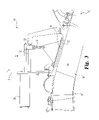
- FIG. 7 is a perspective view of one embodiment of the bleed off valve system of FIG. 5 .
- FIG. 8 is an enlarged partial view of the bleed off valve system of FIG. 7 .
- FIG. 9 is an enlarged partial view of the bleed off valve system of FIG. 7 with the bleed off valve doors in an open condition.
- FIG. 10 is an illustrative view of a bleed off valve system according to another embodiment of the present application.
- an industrial gas turbine engine 10 including, an inlet 12 , a compressor section 14 , a combustor section 16 , a turbine section 18 and an exhaust 22 .
- a portion of the turbine section 18 is arranged to drive the compressor section 14 and a portion of the turbine section 18 drives an electrical generator 26 via a shaft 24 .
- the portion of the turbine section 18 may be arranged to provide drive for other applications.
- the compressor section 14 can include one or more compressors such as a low pressure compressor, an intermediate pressure compressor and a high pressure compressor.
- the bleed off valve system is located between the low pressure compressor and the intermediate pressure compressor.
- industrial gas turbine engine 10 is a non-limiting embodiment and that a variety of other gas turbine engine configurations are also contemplated herein including, for example, gas turbine engines suitable for propulsion of aircraft including helicopters, airplanes, missiles, unmanned space devices and other similar devices, gas turbine engines suitable for pumping sets for oil and gas transmission lines, and as prime movers in a marine propulsion system.
- gas turbine engines suitable for propulsion of aircraft including helicopters, airplanes, missiles, unmanned space devices and other similar devices
- gas turbine engines suitable for pumping sets for oil and gas transmission lines and as prime movers in a marine propulsion system.
- the operation of gas turbine engines is considered conventional and will not be discussed further as it is believed known to one of ordinary skill in the art.
- the present inventions will be described.
- multiple independently rotatable compressors are utilized to pressurize a working fluid in a common flow path it is often desirable to bleed a portion of the working fluid from the common flow path.
- the bleeding of working fluid from the common flow path may be at conditions such as, but not limited to, part power operation, response to transient conditions, and/or prevention of a stall condition.
- the present application contemplates that the working fluid may be air. However, other types of working fluids are contemplated herein.
- One form of the present invention contemplates an industrial gas turbine engine that requires at least a portion of the working fluid to be bled from the common working fluid flow path in varying amounts at part power and/or to respond to transient conditions.
- the industrial gas turbine engine may include a plurality of compressors; such as a low pressure compressor, intermediate pressure compressor and a high pressure compressor.
- the present application contemplates a variety of compressor sections and is not limited to a compressor section including a low pressure compressor, an intermediate pressure compressor and a high pressure compressor unless specifically stated to the contrary.
- the working fluid is bled from gas flow path between the low pressure compressor and the intermediate pressure compressor. The bleeding is accomplished through opening and closing one or more bleed doors located around the outside of the gas flow path.
- the bleed off valves defines a plurality of bleed doors located around the outside of the gas path, and in a preferred form there are 18 doors.
- other quantities of bleed doors are contemplated herein.
- the present application contemplates that the doors may be uniformly or non-uniformly spaced around the flow path and may have a similar or dissimilar shape.
- the plurality of bleed doors define the majority of the outer wall of the gas flow path.
- the present invention is not limited to a system where the plurality of bleed doors define the majority of the outer wall of the gas flow path.
- the plurality of bleed doors When the plurality of bleed doors are opened at least a portion of the working fluid leaves the gas path and is collected in a plenum and then ducted away.
- the plurality of bleed doors, related actuation linkages, and the actuators are located inside the plenum.
- portions of the system such as the actuators are located external to the plenum.
- the gas flow path is decreasing in diameter to accommodate the difference in diameter from the rear of the low pressure compressor to the front of the intermediate pressure compressor.
- the resulted flow path shape in this position results in a substantially conical shaped surface that associates very well with a plurality of discrete bleed doors hinged at one end.
- the flow path may have other shapes such as but not limited to a cylindrical shape.
- the present invention contemplates other door and porting arrangements and is not limited to a bleed doors hinged at one end.
- the flow path defines a cylindrical gas path and the door is defined by a cylindrical sleeve that is moved axially relative to at least one port leading to the plenum.
- a plurality of actuators 20 are coupled to a front wall 21 and located externally of a fluid flow plenum 22 .
- the plurality of actuators 20 are disposed at equally spaced positions and are linked to each bleed door 23 to adjustable rod ends 51 via an idle arm 50 that is guided through a guide shaft 52 in an enclosed bearing shell.
- the actuators may be electric, pneumatic or hydraulic.
- the plurality of actuators 20 provide linear axial movement of a component within the system.
- the plurality of actuators 20 are operable in parallel to move the bleed doors 23 in parallel.
- one form of the present invention contemplates a plurality of bleed doors 23 each having a dedicated actuator 20 for moving the respective bleed door 23 and the actuators 20 are synchronized to move the bleed doors in unison.
- the bleed doors 23 are moveable from a closed position illustrated in FIG. 3 to an open position illustrated in FIG. 4 and vice versa.
- the bleed doors 23 are moved outward from the flow path 60 to allow a portion of the working fluid to exit into a plenum 22 .
- the bleed doors 23 do not move into the flow path 60 .
- the plurality of bleed doors 23 are located around a conical portion 61 of the flow path 60 and between the low pressure compressor section 62 and the intermediate pressure compressor section 63 .
- the conical portion 61 of the flow path includes an outer conical surface 65 to which the plurality of bleed doors 23 engage when in a closed position.
- the system 30 includes a unison ring 31 located within the plenum 22 and coupled between the plurality of actuators 20 and the bleed door linkages 40 .
- the system 30 is one illustrative form of the present invention wherein the plurality of bleed doors 23 are moved together in synchronization.
- the bleed doors 23 are not disposed within the flow path 60 .
- the system 30 is disposed between the low pressure compressor 62 and the intermediate pressure compressor 63 .
- other locations are contemplated herein.
- the actuators 20 are coupled to the wall 21 of the plenum 22 and the unison ring 31 and are operable to move the unison ring 31 axially with a substantially linear motion.
- the unison ring 31 is moved in a linear direction.
- the actuators 20 move the unison ring 31 in a direction substantially parallel with axis X and in a preferred form parallel with the axis X.
- the actuators are hydraulic actuators that are preferably located outside of the plenum 22 .
- each of the actuators 20 is coupled to the unison ring 31 by a self aligning coupling.
- the unison ring 31 is supported on a guide shaft that travels through a tandem linear (sliding) bearing unit. Further the unison ring is connected via linkages 40 to each bleed door 23 .
- FIG. 7 there is illustrated a perspective view of one form of the system 30 of the present invention.
- the plurality of bleed doors 23 is disposed around the conical surface 65 to allow fluid flow from the fluid flow path 60 to the plenum 22 .
- the plurality of actuators 20 are coupled to the unison ring 31 and are operable to move the unison ring 31 in an axial direction parallel with axis X.
- the plurality of bleed doors 23 are coupled to the unison ring 31 via bleed door linkages 40 .
- the unison ring 31 is a hoop continuous structure.
- the unison ring 31 distributes the loads to the plurality of doors 23 during movement of the ring.
- FIG. 8 there is illustrated an extended position of the actuator 20 and in FIG. 9 there is illustrated a retracted position of the actuator 20 .
- a bearing block 50 supports the guide rod 51 and allows linear movement.
- the actuators 20 are coupled to a reinforced wall of the plenum.
- FIG. 10 there is illustrated an alternative system 100 that is utilized with a flow path 110 having a cylindrical outer gas path wall 101 .
- a cylindrical sleeve valve 102 is actuated by an actuator 103 located external to the plenum 105 .
- the present application also contemplates a system where the actuator(s) 103 are located within the plenum 105 .
- the cylindrical sleeve valve 102 is connected to the unison ring 104 by linkage 106 .
- the cylindrical sleeve valve 102 the unison ring 104 and linkage 106 are combined into one ring. The cylindrical sleeve 102 is moved in an axial direction to open and close the fluid flow path into the plenum 105 .
- the present invention further contemplates that the bleed of the working fluid can be taken between stages as an alternative to between compressors. Additionally in some applications the plenum may be unnecessary, in which case the actuator would be supported from a dedicated support structure, which may optionally have the function of acting as a heat shield to protect the actuator from the bleed of the working fluid. As discussed above forms of the present invention may be applicable to other technology areas than gas turbine engines. For example, other types of systems requiring bleeding of fluid from inside a cylindrical/conical duct or chamber could use the embodiments described above.
- the motion of the unison ring is a purely linear motion that translates to a rotary motion of the plurality of bleed doors.
- the unison ring's linear or axial motion is applicable for installation in a wide variety of environments that requires annulus fluid or gas bleed off out of the gas path and/or package.
- the system allows multi-door linkage attachment and can be activated with a minimum of two actuators.
- the unison ring allows for synchronization of the plurality of bleed off valves and the unison ring moves axially with the mass load of the plurality of doors.
- One form of the present application contemplates a system comprising: a first compressor; a second compressor; a passageway connecting said first compressor in fluid flow communication with said second compressor; a unison ring; a plurality of bleed off doors defining a portion of said passageway and located between said compressors, said plurality of bleed off doors coupled to said unison ring; and at least one actuator operable to move said unison ring in a linear direction and actuate said plurality of bleed off doors.
- said at least one actuator defines a plurality of actuators.
- Yet another form of the present invention contemplates the system further includes a plenum located around said plurality of bleed off valves, and wherein the actuation of said plurality of bleed off doors to a non closed position allows a working fluid to pass from said passageway and into said plenum. Yet another form of the present invention contemplates said at least one actuator is located outside of said plenum. Yet another form of the present invention contemplates said plurality of bleed off doors move in unison.
- Yet another form of the present invention contemplates a system wherein each of said plurality of bleed off doors is connected to said unison ring by an attachment linkage; wherein said at least one actuator defines a plurality of actuators; which further includes a plenum located around said plurality of bleed off doors, and wherein the actuation of said plurality of bleed off doors to a non closed position allows a working fluid to pass from said passageway and into said plenum; wherein said at plurality of actuators is located outside of said plenum; and wherein said plurality of bleed off doors move in unison.
- said portion of the passageway has a substantially conical outer shape.
- Another form of the present invention contemplates a system comprising: a first compressor; a second compressor; a passageway connecting said first compressor in fluid flow communication with said second compressor; at least one valve forming at least a portion of said passageway; and actuator means for controlling fluid flow through said at least one valve.
- a system comprising: a gas turbine engine including a first compressor and a second compressor; a passageway connecting said first compressor in fluid flow communication with said second compressor; a plurality of bleed off valves defining a portion of said passageway and located between said compressors; and a plurality of linear actuators, one of said plurality of linear actuators is coupled to each of said plurality of bleed off valves and operable to move said valve between and an open state and a closed state.
- a method for bleeding a working fluid from a gas turbine engine comprising: compressing the working fluid in a first compressor; flowing the working fluid from the first compressor through a passageway towards a second compressor; moving a unison ring linearly to open a plurality of bleed off doors forming a portion of the passageway after the first compressor; and passing at a portion of the working fluid through the opened bleed off doors.
Landscapes
- Engineering & Computer Science (AREA)
- Mechanical Engineering (AREA)
- General Engineering & Computer Science (AREA)
- Chemical & Material Sciences (AREA)
- Combustion & Propulsion (AREA)
- Life Sciences & Earth Sciences (AREA)
- Sustainable Development (AREA)
- Physics & Mathematics (AREA)
- Fluid Mechanics (AREA)
- Structures Of Non-Positive Displacement Pumps (AREA)
- Fluid-Driven Valves (AREA)
- Control Of Turbines (AREA)
Abstract
Description
Claims (15)
Priority Applications (1)
| Application Number | Priority Date | Filing Date | Title |
|---|---|---|---|
| US11/706,691 US7594403B2 (en) | 2006-01-20 | 2007-02-15 | Bleed off valve system |
Applications Claiming Priority (3)
| Application Number | Priority Date | Filing Date | Title |
|---|---|---|---|
| US76060306P | 2006-01-20 | 2006-01-20 | |
| PCT/IB2007/001571 WO2007116319A2 (en) | 2006-01-20 | 2007-01-22 | Bleed off valve system |
| US11/706,691 US7594403B2 (en) | 2006-01-20 | 2007-02-15 | Bleed off valve system |
Related Parent Applications (1)
| Application Number | Title | Priority Date | Filing Date |
|---|---|---|---|
| USPCT/US07/01578 Continuation | 2007-01-22 |
Publications (2)
| Publication Number | Publication Date |
|---|---|
| US20080028764A1 US20080028764A1 (en) | 2008-02-07 |
| US7594403B2 true US7594403B2 (en) | 2009-09-29 |
Family
ID=38578568
Family Applications (1)
| Application Number | Title | Priority Date | Filing Date |
|---|---|---|---|
| US11/706,691 Active 2027-11-08 US7594403B2 (en) | 2006-01-20 | 2007-02-15 | Bleed off valve system |
Country Status (3)
| Country | Link |
|---|---|
| US (1) | US7594403B2 (en) |
| GB (2) | GB2443982B (en) |
| WO (1) | WO2007116319A2 (en) |
Cited By (24)
| Publication number | Priority date | Publication date | Assignee | Title |
|---|---|---|---|---|
| US20100080684A1 (en) * | 2008-09-30 | 2010-04-01 | Snecma | System for controlling variable-geometry equipments of a turbomachine, particularly by articulated bellcranks |
| US20100158663A1 (en) * | 2008-09-30 | 2010-06-24 | Snecma | System for controlling at least two variable-geometry equipments of a gas turbine engine, particularly by cam mechanism |
| US20100158662A1 (en) * | 2008-09-30 | 2010-06-24 | Snecma | System for controlling at least two variable-geometry equipments of a gas turbine engine, particularly by rack |
| US20130001892A1 (en) * | 2011-06-29 | 2013-01-03 | Smith Darren M | Fan duct blocker actuation tab seal |
| US20130039748A1 (en) * | 2011-07-09 | 2013-02-14 | Ramgen Power Systems, Llc | Stator for supersonic compressor |
| FR2982904A1 (en) * | 2011-11-18 | 2013-05-24 | Snecma | CARTER HUB FOR AN AIRCRAFT AIRCRAFT COMPRISING MEANS FOR CONTROLLING IMPROVED DISCHARGE VALVES |
| US20140245747A1 (en) * | 2012-10-12 | 2014-09-04 | General Electric Company | Gas turbine engine two degree of freedom variable bleed valve for ice extraction |
| DE102013215371A1 (en) | 2013-08-05 | 2015-02-05 | Rolls-Royce Deutschland Ltd & Co Kg | Apparatus and method for blowing off compressor air in an engine |
| US20150101481A1 (en) * | 2012-05-07 | 2015-04-16 | Snecma | Method for improved assembly of an actuator for an air bleed valve of a turbine engine |
| US20150211540A1 (en) * | 2014-01-24 | 2015-07-30 | Pratt & Whitney Canada Corp. | Bleed valve |
| US9103283B2 (en) | 2012-06-20 | 2015-08-11 | United Technologies Corporation | Spherical-link end damper system with near constant engagement |
| US9394792B2 (en) | 2012-10-01 | 2016-07-19 | United Technologies Corporation | Reduced height ligaments to minimize non-integral vibrations in rotor blades |
| US9657647B2 (en) | 2013-10-15 | 2017-05-23 | The Boeing Company | Methods and apparatus to adjust bleed ports on an aircraft engine |
| US20170284306A1 (en) * | 2016-03-31 | 2017-10-05 | Safran Aircraft Engines | Aircraft turbine engine comprising a discharge device |
| US20180252184A1 (en) * | 2017-03-01 | 2018-09-06 | General Electric Company | Variable bleed valve door assembly and system |
| US10233782B2 (en) | 2016-08-03 | 2019-03-19 | Solar Turbines Incorporated | Turbine assembly and method for flow control |
| US10767562B2 (en) | 2014-12-10 | 2020-09-08 | Pratt & Whitney Canada Corp. | Modulated cooled P3 air for impeller |
| EP3907389A1 (en) * | 2020-05-08 | 2021-11-10 | Raytheon Technologies Corporation | Gas turbine compressor radial door bleed valve |
| US11346240B2 (en) * | 2019-06-07 | 2022-05-31 | Raytheon Technologies Corporation | Gas turbine engine bleed valve damping guide link |
| US12066027B2 (en) | 2022-08-11 | 2024-08-20 | Next Gen Compression Llc | Variable geometry supersonic compressor |
| US12320259B2 (en) | 2022-06-27 | 2025-06-03 | General Electric Company | Compact bleed valve assemblies |
| US12366202B2 (en) | 2022-01-18 | 2025-07-22 | General Electric Company | Bleed valve assemblies |
| US12460651B2 (en) | 2022-08-11 | 2025-11-04 | Next Gen Compression Llc | Method for efficient part load compressor operation |
| US12553403B1 (en) | 2025-07-23 | 2026-02-17 | General Electric Company | Gas turbine engine having a thrust reverser system with drag link connectors at inter-compressor frame structure |
Families Citing this family (15)
| Publication number | Priority date | Publication date | Assignee | Title |
|---|---|---|---|---|
| FR2932855B1 (en) * | 2008-06-18 | 2014-04-11 | Snecma | <p> AIR DISCHARGE SYSTEM FOR AERONAUTICAL TURBOMACHINE COMPRESSOR </ p> |
| FR2936557B1 (en) * | 2008-09-30 | 2017-04-21 | Snecma | SYSTEM FOR CONTROLLING VARIABLE GEOMETRY EQUIPMENT OF A GAS TURBINE ENGINE COMPRISING IN PARTICULAR A CONNECTION BY GUIDE RUNS. |
| FR2936559B1 (en) * | 2008-09-30 | 2013-11-22 | Snecma | SYSTEM FOR CONTROLLING EQUIPMENT WITH VARIABLE GEOMETRY OF A TURBOMACHINE CONSISTING OF DIFFERENT BODIES. |
| FR2936558B1 (en) * | 2008-09-30 | 2016-11-11 | Snecma | SYSTEM FOR CONTROLLING EQUIPMENT WITH VARIABLE GEOMETRY OF A GAS TURBINE ENGINE INCLUDING, IN PARTICULAR, A BARREL LINK. |
| FR2936556B1 (en) * | 2008-09-30 | 2015-07-24 | Snecma | SYSTEM FOR CONTROLLING EQUIPMENT WITH VARIABLE GEOMETRY OF A TURBOMACHINE, IN PARTICULAR BY GUIGNOLS. |
| FR2955646B1 (en) * | 2010-01-26 | 2012-08-24 | Ge Energy Products France Snc | VENTILATION SYSTEM AND METHOD FOR TURBINE |
| US9032739B2 (en) | 2011-04-11 | 2015-05-19 | Hamilton Sundstrand Corporation | Load limited actuator |
| CN103925114B (en) * | 2014-04-24 | 2015-12-09 | 北京航空航天大学 | A roller slider translational front duct ejector in an adjustable mechanism of a variable cycle engine |
| DE102014221049A1 (en) * | 2014-10-16 | 2016-04-21 | Rolls-Royce Deutschland Ltd & Co Kg | Arrangement and method for blowing off compressor air in an engine |
| CN105545522B (en) * | 2015-12-29 | 2017-04-12 | 中国航空工业集团公司沈阳发动机设计研究所 | Mode selector valve assembly |
| GB201610312D0 (en) | 2016-06-14 | 2016-07-27 | Rolls-Royce Controls And Data Services Ltd | Compressor geometry control |
| FR3059366B1 (en) * | 2016-11-25 | 2020-10-30 | Safran Aircraft Engines | DOUBLE-FLOW TURBOMACHINE EQUIPPED WITH A DISCHARGE SYSTEM |
| FR3082562B1 (en) | 2018-06-19 | 2020-06-12 | Safran Aircraft Engines | DISCHARGE DOOR CONTROL RING FOR AN AIRCRAFT TURBOMACHINE AND TURBOMACHINE COMPRISING SAME |
| CN111058946A (en) * | 2019-12-05 | 2020-04-24 | 中国航发四川燃气涡轮研究院 | Compressor bypass air entraining device and system |
| CN113719623B (en) * | 2021-09-15 | 2023-09-22 | 中国航空发动机研究院 | Valve for annular channel of aero-engine |
Citations (21)
| Publication number | Priority date | Publication date | Assignee | Title |
|---|---|---|---|---|
| US3584458A (en) | 1969-11-25 | 1971-06-15 | Gen Motors Corp | Turbine cooling |
| US3638428A (en) | 1970-05-04 | 1972-02-01 | Gen Electric | Bypass valve mechanism |
| US4344282A (en) * | 1980-12-16 | 1982-08-17 | United Technologies Corporation | Compressor bleed system |
| US4390318A (en) | 1977-09-10 | 1983-06-28 | Mtu Motoren-Und Turbinen-Union Muenche Gmbh | Apparatus for operating shut-off members in gas turbine engines, particularly in turbojet engines |
| US4409788A (en) | 1979-04-23 | 1983-10-18 | General Electric Company | Actuation system for use on a gas turbine engine |
| US4715779A (en) | 1984-12-13 | 1987-12-29 | United Technologies Corporation | Bleed valve for axial flow compressor |
| US5044153A (en) | 1988-12-15 | 1991-09-03 | Societe Nationale D'etude Et De Construction De Moteurs D'aviation "S.N.E.C.M.A." | Turbojet compressor blow off valves with water collecting and discharge means |
| US5261228A (en) | 1992-06-25 | 1993-11-16 | General Electric Company | Apparatus for bleeding air |
| US5279109A (en) | 1991-09-03 | 1994-01-18 | General Electric Company | Gas turbine engine variable bleed pivotal flow splitter |
| US5515673A (en) | 1991-10-23 | 1996-05-14 | Societe Nationale D'etude Et De Construction De Moteurs D'aviation "S.N.E.C.M.A" | Device for controlling the opening and closing of discharge valves of a turbojet engine |
| US5687562A (en) | 1995-06-30 | 1997-11-18 | United Technologies Corporation | Bypass air valve for turbofan engine |
| US5775098A (en) | 1995-06-30 | 1998-07-07 | United Technologies Corporation | Bypass air valve for a gas turbine |
| US5845482A (en) | 1994-10-06 | 1998-12-08 | Carscallen; William E. | Combined bleed valve and annular diffuser for gas turbine inter compressor duct |
| US6048171A (en) | 1997-09-09 | 2000-04-11 | United Technologies Corporation | Bleed valve system |
| US6122905A (en) | 1998-02-13 | 2000-09-26 | Pratt & Whitney Canada Corp. | Compressor bleed valve |
| US6161839A (en) | 1998-02-27 | 2000-12-19 | United Technologies Corporation | Valve seal assembly |
| US6647708B2 (en) | 2002-03-05 | 2003-11-18 | Williams International Co., L.L.C. | Multi-spool by-pass turbofan engine |
| US20040096315A1 (en) | 2002-11-19 | 2004-05-20 | Wieslaw Chlus | Maintainable compressor stability bleed system |
| US6742324B2 (en) | 2002-09-13 | 2004-06-01 | General Electric Company | Methods and apparatus for supporting variable bypass valve systems |
| US6755025B2 (en) | 2002-07-23 | 2004-06-29 | Pratt & Whitney Canada Corp. | Pneumatic compressor bleed valve |
| US6851255B2 (en) | 2002-12-18 | 2005-02-08 | Pratt & Whitney Canada Corp. | Normally open reverse flow flapper valve |
Family Cites Families (1)
| Publication number | Priority date | Publication date | Assignee | Title |
|---|---|---|---|---|
| CA2208801C (en) * | 1997-06-24 | 2005-12-06 | Rolls-Royce Plc | A bleed apparatus for a gas turbine engine |
-
2007
- 2007-01-22 GB GB0802248A patent/GB2443982B/en not_active Expired - Fee Related
- 2007-01-22 WO PCT/IB2007/001571 patent/WO2007116319A2/en not_active Ceased
- 2007-01-22 GB GB1022088A patent/GB2473578B/en active Active
- 2007-02-15 US US11/706,691 patent/US7594403B2/en active Active
Patent Citations (22)
| Publication number | Priority date | Publication date | Assignee | Title |
|---|---|---|---|---|
| US3584458A (en) | 1969-11-25 | 1971-06-15 | Gen Motors Corp | Turbine cooling |
| US3638428A (en) | 1970-05-04 | 1972-02-01 | Gen Electric | Bypass valve mechanism |
| US4390318A (en) | 1977-09-10 | 1983-06-28 | Mtu Motoren-Und Turbinen-Union Muenche Gmbh | Apparatus for operating shut-off members in gas turbine engines, particularly in turbojet engines |
| US4409788A (en) | 1979-04-23 | 1983-10-18 | General Electric Company | Actuation system for use on a gas turbine engine |
| US4344282A (en) * | 1980-12-16 | 1982-08-17 | United Technologies Corporation | Compressor bleed system |
| US4715779A (en) | 1984-12-13 | 1987-12-29 | United Technologies Corporation | Bleed valve for axial flow compressor |
| US5044153A (en) | 1988-12-15 | 1991-09-03 | Societe Nationale D'etude Et De Construction De Moteurs D'aviation "S.N.E.C.M.A." | Turbojet compressor blow off valves with water collecting and discharge means |
| US5279109A (en) | 1991-09-03 | 1994-01-18 | General Electric Company | Gas turbine engine variable bleed pivotal flow splitter |
| US5515673A (en) | 1991-10-23 | 1996-05-14 | Societe Nationale D'etude Et De Construction De Moteurs D'aviation "S.N.E.C.M.A" | Device for controlling the opening and closing of discharge valves of a turbojet engine |
| US5351473A (en) * | 1992-06-25 | 1994-10-04 | General Electric Company | Method for bleeding air |
| US5261228A (en) | 1992-06-25 | 1993-11-16 | General Electric Company | Apparatus for bleeding air |
| US5845482A (en) | 1994-10-06 | 1998-12-08 | Carscallen; William E. | Combined bleed valve and annular diffuser for gas turbine inter compressor duct |
| US5687562A (en) | 1995-06-30 | 1997-11-18 | United Technologies Corporation | Bypass air valve for turbofan engine |
| US5775098A (en) | 1995-06-30 | 1998-07-07 | United Technologies Corporation | Bypass air valve for a gas turbine |
| US6048171A (en) | 1997-09-09 | 2000-04-11 | United Technologies Corporation | Bleed valve system |
| US6122905A (en) | 1998-02-13 | 2000-09-26 | Pratt & Whitney Canada Corp. | Compressor bleed valve |
| US6161839A (en) | 1998-02-27 | 2000-12-19 | United Technologies Corporation | Valve seal assembly |
| US6647708B2 (en) | 2002-03-05 | 2003-11-18 | Williams International Co., L.L.C. | Multi-spool by-pass turbofan engine |
| US6755025B2 (en) | 2002-07-23 | 2004-06-29 | Pratt & Whitney Canada Corp. | Pneumatic compressor bleed valve |
| US6742324B2 (en) | 2002-09-13 | 2004-06-01 | General Electric Company | Methods and apparatus for supporting variable bypass valve systems |
| US20040096315A1 (en) | 2002-11-19 | 2004-05-20 | Wieslaw Chlus | Maintainable compressor stability bleed system |
| US6851255B2 (en) | 2002-12-18 | 2005-02-08 | Pratt & Whitney Canada Corp. | Normally open reverse flow flapper valve |
Non-Patent Citations (1)
| Title |
|---|
| Partial Int'l Search Rept, PCT/IB2007/001571. |
Cited By (42)
| Publication number | Priority date | Publication date | Assignee | Title |
|---|---|---|---|---|
| US20100080684A1 (en) * | 2008-09-30 | 2010-04-01 | Snecma | System for controlling variable-geometry equipments of a turbomachine, particularly by articulated bellcranks |
| US20100158663A1 (en) * | 2008-09-30 | 2010-06-24 | Snecma | System for controlling at least two variable-geometry equipments of a gas turbine engine, particularly by cam mechanism |
| US20100158662A1 (en) * | 2008-09-30 | 2010-06-24 | Snecma | System for controlling at least two variable-geometry equipments of a gas turbine engine, particularly by rack |
| US8328500B2 (en) * | 2008-09-30 | 2012-12-11 | Snecma | System for controlling variable-geometry equipments of a turbomachine, particularly by articulated bellcranks |
| US8333546B2 (en) * | 2008-09-30 | 2012-12-18 | Snecma | System for controlling at least two variable-geometry equipments of a gas turbine engine, particularly by cam mechanism |
| US8337140B2 (en) * | 2008-09-30 | 2012-12-25 | Snecma | System for controlling at least two variable-geometry equipments of a gas turbine engine, particularly by rack |
| US20130001892A1 (en) * | 2011-06-29 | 2013-01-03 | Smith Darren M | Fan duct blocker actuation tab seal |
| US8919784B2 (en) * | 2011-06-29 | 2014-12-30 | United Technologies Corporation | Fan duct blocker actuation tab seal |
| US20130039748A1 (en) * | 2011-07-09 | 2013-02-14 | Ramgen Power Systems, Llc | Stator for supersonic compressor |
| US9309893B2 (en) * | 2011-07-09 | 2016-04-12 | Dresser-Rand Company | Supersonic compressor |
| US20130142632A1 (en) * | 2011-07-09 | 2013-06-06 | Ramgen Power Systems, Llc | Supersonic compressor |
| US20130164121A1 (en) * | 2011-07-09 | 2013-06-27 | Ramgen Power Systems, Llc | Supersonic compressor |
| US20130164120A1 (en) * | 2011-07-09 | 2013-06-27 | Ramgen Power Systems, Llc | Supersonic compressor |
| FR2982904A1 (en) * | 2011-11-18 | 2013-05-24 | Snecma | CARTER HUB FOR AN AIRCRAFT AIRCRAFT COMPRISING MEANS FOR CONTROLLING IMPROVED DISCHARGE VALVES |
| US9897012B2 (en) * | 2012-05-07 | 2018-02-20 | Snecma | Method for improved assembly of an actuator for an air bleed valve of a turbine engine |
| US20150101481A1 (en) * | 2012-05-07 | 2015-04-16 | Snecma | Method for improved assembly of an actuator for an air bleed valve of a turbine engine |
| US9103283B2 (en) | 2012-06-20 | 2015-08-11 | United Technologies Corporation | Spherical-link end damper system with near constant engagement |
| US9394792B2 (en) | 2012-10-01 | 2016-07-19 | United Technologies Corporation | Reduced height ligaments to minimize non-integral vibrations in rotor blades |
| US9518513B2 (en) * | 2012-10-12 | 2016-12-13 | General Electric Company | Gas turbine engine two degree of freedom variable bleed valve for ice extraction |
| US20140245747A1 (en) * | 2012-10-12 | 2014-09-04 | General Electric Company | Gas turbine engine two degree of freedom variable bleed valve for ice extraction |
| EP2835522A1 (en) | 2013-08-05 | 2015-02-11 | Rolls-Royce Deutschland Ltd & Co KG | Device and method for letting off compressor air in an engine |
| DE102013215371A1 (en) | 2013-08-05 | 2015-02-05 | Rolls-Royce Deutschland Ltd & Co Kg | Apparatus and method for blowing off compressor air in an engine |
| US9506424B2 (en) | 2013-08-05 | 2016-11-29 | Rolls-Royce Deutschland Ltd & Co Kg | Apparatus and method for bleeding off compressor air in a jet engine |
| US10626801B2 (en) | 2013-10-15 | 2020-04-21 | The Boeing Company | Methods and apparatus to adjust bleed ports on an aircraft engine |
| US9657647B2 (en) | 2013-10-15 | 2017-05-23 | The Boeing Company | Methods and apparatus to adjust bleed ports on an aircraft engine |
| US9651053B2 (en) * | 2014-01-24 | 2017-05-16 | Pratt & Whitney Canada Corp. | Bleed valve |
| US20150211540A1 (en) * | 2014-01-24 | 2015-07-30 | Pratt & Whitney Canada Corp. | Bleed valve |
| US10767562B2 (en) | 2014-12-10 | 2020-09-08 | Pratt & Whitney Canada Corp. | Modulated cooled P3 air for impeller |
| US11230978B2 (en) * | 2016-03-31 | 2022-01-25 | Safran Aircraft Engines | Aircraft turbine engine comprising a discharge device |
| US20170284306A1 (en) * | 2016-03-31 | 2017-10-05 | Safran Aircraft Engines | Aircraft turbine engine comprising a discharge device |
| US10233782B2 (en) | 2016-08-03 | 2019-03-19 | Solar Turbines Incorporated | Turbine assembly and method for flow control |
| US20180252184A1 (en) * | 2017-03-01 | 2018-09-06 | General Electric Company | Variable bleed valve door assembly and system |
| US10830179B2 (en) | 2017-03-01 | 2020-11-10 | General Electric Company | Variable bleed valve door assembly and system for gas turbine engines |
| US11346240B2 (en) * | 2019-06-07 | 2022-05-31 | Raytheon Technologies Corporation | Gas turbine engine bleed valve damping guide link |
| EP3907389A1 (en) * | 2020-05-08 | 2021-11-10 | Raytheon Technologies Corporation | Gas turbine compressor radial door bleed valve |
| US11428234B2 (en) | 2020-05-08 | 2022-08-30 | Raytheon Technologies Corporation | Gas turbine compressor radial door bleed valve |
| US12366202B2 (en) | 2022-01-18 | 2025-07-22 | General Electric Company | Bleed valve assemblies |
| US12320259B2 (en) | 2022-06-27 | 2025-06-03 | General Electric Company | Compact bleed valve assemblies |
| US12066027B2 (en) | 2022-08-11 | 2024-08-20 | Next Gen Compression Llc | Variable geometry supersonic compressor |
| US12338829B2 (en) | 2022-08-11 | 2025-06-24 | Next Gen Compression Llc | Variable geometry supersonic compressor |
| US12460651B2 (en) | 2022-08-11 | 2025-11-04 | Next Gen Compression Llc | Method for efficient part load compressor operation |
| US12553403B1 (en) | 2025-07-23 | 2026-02-17 | General Electric Company | Gas turbine engine having a thrust reverser system with drag link connectors at inter-compressor frame structure |
Also Published As
| Publication number | Publication date |
|---|---|
| GB0802248D0 (en) | 2008-03-12 |
| WO2007116319A2 (en) | 2007-10-18 |
| GB2443982B (en) | 2011-06-22 |
| GB2473578A (en) | 2011-03-16 |
| GB2473578B (en) | 2011-08-03 |
| US20080028764A1 (en) | 2008-02-07 |
| WO2007116319A3 (en) | 2008-04-03 |
| GB201022088D0 (en) | 2011-02-02 |
| GB2443982A (en) | 2008-05-21 |
Similar Documents
| Publication | Publication Date | Title |
|---|---|---|
| US7594403B2 (en) | Bleed off valve system | |
| CN108533407B (en) | Variable bleed valve assembly and system | |
| US9476362B2 (en) | Turbomachine with bleed valves located at the intermediate case | |
| US6899513B2 (en) | Inflatable compressor bleed valve system | |
| EP0723630B1 (en) | Axially opening cylindrical bleed valve | |
| US10502086B2 (en) | System and method for actuating gas turbine engine components using integrated jamming devices | |
| US20100006165A1 (en) | Hydraulically actuated pneumatic regulator | |
| US8157241B2 (en) | Methods and apparatus for regulating gas turbine engine fluid flow | |
| EP3591204A1 (en) | Thrust reverser with displaceable trailing edge body | |
| US7540144B2 (en) | Bleed valve for a gas turbine engine | |
| EP2153028A1 (en) | A device for moving a plurality of hatches in a gas turbine engine | |
| EP3816423B1 (en) | An exhaust nozzle for a gas turbine engine | |
| EP3358149B1 (en) | Bleed valve with neutral or closing bias | |
| EP3430240B1 (en) | Turbine arrangement | |
| US12270348B2 (en) | Sealing device for a discharge valve of a turbomachine | |
| EP2369140A2 (en) | Steam seal system | |
| US8347601B2 (en) | Device for pivoting at least one pivotable element in a gas turbine engine | |
| EP3287627A1 (en) | Aircraft thrust reverser system with hydraulic assist device | |
| GB2261917A (en) | Valve for diverting fluid flows in turbomachines |
Legal Events
| Date | Code | Title | Description |
|---|---|---|---|
| AS | Assignment |
Owner name: ROLLS-ROYCE POWER ENGINEERING PLC, ENGLAND Free format text: ASSIGNMENT OF ASSIGNORS INTEREST;ASSIGNOR:CADIEUX, MICHEL;REEL/FRAME:019386/0360 Effective date: 20070221 |
|
| STCF | Information on status: patent grant |
Free format text: PATENTED CASE |
|
| FEPP | Fee payment procedure |
Free format text: PAYOR NUMBER ASSIGNED (ORIGINAL EVENT CODE: ASPN); ENTITY STATUS OF PATENT OWNER: LARGE ENTITY |
|
| FPAY | Fee payment |
Year of fee payment: 4 |
|
| FEPP | Fee payment procedure |
Free format text: PAYOR NUMBER ASSIGNED (ORIGINAL EVENT CODE: ASPN); ENTITY STATUS OF PATENT OWNER: LARGE ENTITY Free format text: PAYER NUMBER DE-ASSIGNED (ORIGINAL EVENT CODE: RMPN); ENTITY STATUS OF PATENT OWNER: LARGE ENTITY |
|
| AS | Assignment |
Owner name: INDUSTRIAL TURBINE COMPANY (UK) LIMITED, UNITED KI Free format text: ASSIGNMENT OF ASSIGNORS INTEREST;ASSIGNOR:ROLLS-ROYCE POWER ENGINEERING PLC;REEL/FRAME:035035/0491 Effective date: 20140803 |
|
| FPAY | Fee payment |
Year of fee payment: 8 |
|
| MAFP | Maintenance fee payment |
Free format text: PAYMENT OF MAINTENANCE FEE, 12TH YEAR, LARGE ENTITY (ORIGINAL EVENT CODE: M1553); ENTITY STATUS OF PATENT OWNER: LARGE ENTITY Year of fee payment: 12 |