US7581281B2 - Ultra-compact recessed wall mounted vacuum cleaner - Google Patents
Ultra-compact recessed wall mounted vacuum cleaner Download PDFInfo
- Publication number
- US7581281B2 US7581281B2 US11/072,684 US7268405A US7581281B2 US 7581281 B2 US7581281 B2 US 7581281B2 US 7268405 A US7268405 A US 7268405A US 7581281 B2 US7581281 B2 US 7581281B2
- Authority
- US
- United States
- Prior art keywords
- housing
- vacuum
- motor
- assembly
- chamber
- Prior art date
- Legal status (The legal status is an assumption and is not a legal conclusion. Google has not performed a legal analysis and makes no representation as to the accuracy of the status listed.)
- Active, expires
Links
Images


Classifications
-
- A—HUMAN NECESSITIES
- A47—FURNITURE; DOMESTIC ARTICLES OR APPLIANCES; COFFEE MILLS; SPICE MILLS; SUCTION CLEANERS IN GENERAL
- A47L—DOMESTIC WASHING OR CLEANING; SUCTION CLEANERS IN GENERAL
- A47L5/00—Structural features of suction cleaners
- A47L5/12—Structural features of suction cleaners with power-driven air-pumps or air-compressors, e.g. driven by motor vehicle engine vacuum
- A47L5/22—Structural features of suction cleaners with power-driven air-pumps or air-compressors, e.g. driven by motor vehicle engine vacuum with rotary fans
- A47L5/38—Built-in suction cleaner installations, i.e. with fixed tube system to which, at different stations, hoses can be connected
-
- A—HUMAN NECESSITIES
- A47—FURNITURE; DOMESTIC ARTICLES OR APPLIANCES; COFFEE MILLS; SPICE MILLS; SUCTION CLEANERS IN GENERAL
- A47L—DOMESTIC WASHING OR CLEANING; SUCTION CLEANERS IN GENERAL
- A47L9/00—Details or accessories of suction cleaners, e.g. mechanical means for controlling the suction or for effecting pulsating action; Storing devices specially adapted to suction cleaners or parts thereof; Carrying-vehicles specially adapted for suction cleaners
- A47L9/0081—Means for exhaust-air diffusion; Means for sound or vibration damping
Definitions
- This invention relates to the field of wall mounted vacuum cleaners and particularly to an improved self-contained unit capable of being totally recessed within an interior wall and operating with a greatly reduced noise level.
- Central vacuum cleaning systems are useful in homes, offices and commercial establishments. These systems generally utilize a unitary centrally located station containing a vacuum supply, a collection receptacle and a plurality of conduits which interconnect various parts of the structure to the central station.
- the conduits normally terminate in a hose adapter coupling enabling each area to be cleaned by inserting the hose assembly into the hose coupling and activating the central station vacuum supply.
- the hose assembly is normally moved from one room to another.
- the hose coupling also supplies electrical power to a brushing system, sometimes referred to as a powerhead.
- the instant invention incorporates a unique baffle assembly which advantageously lines the inner walls of the housing around the collection receptacle and maintains an unimpeded flow path so as to insure optimum operation, even as the receptacle becomes filled.
- Wall recessed cleaning systems are known that are self-contained so as to include the vacuum supply, vacuum bag and hose receptacle in a single unit, adapted to be situated within an opening prepared in the wall of an existing structure.
- the problem with such prior art devices was that they were difficult to install within an interior wall recess since they were greater than 6 inches in depth.
- Another problem was that the geometry of the motor structure necessitated use of an inefficient flow pattern in order to reduce the unit's overall dimensions.
- U.S. Pat. No. 6,158,080 to Schlapkohl the inventor of the instant improvement, is incorporated herein by reference.
- the patent teaches the provision of a small, compact, powerful, self-contained, wall mounted central vacuum system.
- the vacuum cleaner has a housing that encloses the air filtering and residue collection chamber together with the motor producing the air flow.
- the residue collection chamber is designed to incorporate easily removable and disposable bags.
- the housing includes hardware for mounting the vacuum cleaner on or recessed in a wall along with inlet and exhaust openings. The vacuum cleaner can simultaneously provide powerful and reliable cleaning without loss of efficiency as debris is collected.
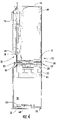
- FIG. 1 is a front plan view of the vacuum system with the assembly removed;
- FIG. 2 a is a top view of the motor shroud
- FIG. 2 b is a front view of the motor shroud
- FIG. 3 is a top view of the supporting grid element
- FIG. 4 is a side plan view of the vacuum system
- FIG. 5 is a front plan view of the access panel latch
- FIG. 6 is a front plan view of the cover assembly
- FIG. 7 is a plain view of the inside of the cover assembly.
- FIGS. 8 a, 8 b, and 8 c are an orthographic projection view of a vertical baffle assembly.
- the wall-mounted vacuum system of the instant invention is characterized by a front cover frame assembly 50 and an open faced housing 10 .
- the open-faced rectangular housing 10 has a rear wall 12 , two side walls 14 , 14 A, a top wall 16 and a bottom wall 18 .
- the top wall and adjacent side walls each have a perpendicular flange 20 adjacent the front face thereof containing a series of spaced perforations 22 . These perforations aid in the accurate positioning of the cover frame assembly 50 by accepting alignment tabs 52 which are molded about the perimeter of the rear side of the cover frame assembly.
- the front cover frame assembly 50 includes a flange 21 , illustrated in FIG. 7 .
- Flange 21 and flange 20 are constructed and arranged to provide a sealing engagement between the front cover frame assembly and housing 10 .
- a seal (not shown) can be placed in between the flange 20 and flange 21 to provide a sealing engagement between the front cover assembly 50 and the housing 10 .
- the system components are constructed and arranged so as to mount within the open-faced rectangular housing 10 .
- the housing 10 and cover frame assembly 50 may be formed of stainless steel or galvanized sheet metal. Alternatively, they may be molded from ABS or polycarbonate/ABS blend.
- the minimal depth of the housing 10 enables it to fit within the recess created when an opening is formed between the studs of a standard wall construction.
- a peripheral flange 20 extends perpendicularly from the sidewalls 14 , 14 A at the outermost edge thereof so as to provide a rigid surface for firmly positioning the housing adjacent to the wall face.
- the positioning of components and compact motor design result in the housing 10 having a depth of only 37 ⁇ 8 inches.
- the arcuate projection of the front cover frame 50 adds 13/16 inch resulting in a device having a total depth of only 4 11/16 inches.
- the minimal depth required for installation permits placement of the unit in any partition structure, for example gypsum board walls, plaster walls, and fiberglass or metal panels found in boats or recreational vehicles.
- the open faced housing 10 has an upper containment compartment 26 and a lower evacuation compartment 28 separated by a partition assembly 24 .
- the containment compartment 26 supports an air filtering and residue collecting receptacle, such as a removable vacuum bag 49 , and a coupling adapter 74 to attach a vacuum hose (not shown) which communicates with the inside of the bag.
- the partition 24 has a thin extension 84 that projects beyond the side walls and fits within a transverse channel 85 in the cover frame assembly 50 to seal the containment compartment except for the central circular opening 43 . This prevents entrained air from spilling over the partition 24 into the evacuation chamber 28 creating back pressure and vibration between the cover frame 50 and the housing 10 .
- the sidewalls 14 , 14 A have integral positioning members 44 which support the internal components while simultaneously insuring unimpeded airflow between the containment and evacuation compartments.
- These positioning members 44 may be in the form of upstanding ridges or alternatively may constitute channels which may be machined or molded into the sidewall construction thereby stiffening the wall structure and reducing vibration.
- a vertical baffle assembly including positioning members 44 , is molded or otherwise integrally attached in spaced relation to the rear wall 12 of the housing, also strengthening the housing 10 .
- the positioning of these positioning members allows optimum air flow to be maintained between the containment chamber and the evacuation chamber, even as the collection receptacle becomes filled during use.
- the vertical baffle assembly can be in the form of a plurality of members which contain vertical ribs in spaced relation to the housing sidewalls and rear wall so as to thereby create an area for unrestricted air flow throughout the containment chamber, as illustrated in FIGS. 8A-C .
- supporting grid element 40 termed a bag grid
- This member which in a preferred embodiment is formed from a flame retardant ABS resin, contains a plurality of baffles 47 circumferentially spaced about the central opening 43 and designed to provide rigid support for the overlying bag.
- baffles 47 circumferentially spaced about the central opening 43 and designed to provide rigid support for the overlying bag.
- the bag grid provides overall support along the bottom of the bag structure thereby preventing the mesh filter 38 from being deformed. By fully supporting the bag and preventing filter deformation, uniform flow rate is maintained throughout the vacuum cleaner assembly and efficient cleaning can be attained.
- the chamber separating partition assembly 24 containing a bag supporting grid element, a motor protecting filter element and a motor shroud element, is situated between the motor and the air filtering and collection receptacle.
- the chamber separating assembly 24 serves a two-fold function. Firstly, the spaced relationship of the bag support grid element, motor protecting filter element and motor shroud provide support for the air filtration and debris collecting receptacle above the motor housing and help to insure a uniform and unimpeded flow of air to the suction fan and motor housing. Secondly, the underside of the motor shroud provides a downwardly directed member which frictionally engages the flow-thru motor assembly 30 so as to provide reliable and rigid support therefore.
- An air flow divider 80 is molded to the rear wall 12 and the bottom wall 18 of the evacuation compartment 28 .
- the air flow divider 80 is a thin curved flange that extends beyond the side walls 14 , 14 A and terminates in an outermost edge 81 .
- the outermost edge 81 cooperates with a curved channel 86 in the front cover frame 50 to subdivide the evacuation compartment into a central plenum 83 and an outer airway 83 ′.
- An air exhaust is located at the bottom of the unit.
- the exhaust is formed by an outlet grid 56 extending between the cover frame 50 and the housing 10 . Because a portion of the air flow divider 80 extends past the side walls of the housing, the air flow is directed through the grid 56 .
- a final filter 58 is supported by the grid. The filter prevents debris from re-entry into the room and further muffles the sound of the device.
- the lower section or evacuation chamber 28 contains the flow-thru motor housing assembly 30 which is comprised of a compact flow-thru vacuum motor 32 which draws air therethrough so as to create an area of lower pressure within the containment chamber.
- the bottom surface of the partition assembly 24 is defined by a motor shroud 36 .
- the motor shroud contains an upstanding and generally circular flange adapted to frictionally engage the flow-thru motor assembly 30 so as to precisely position the source of vacuum beneath the shroud.
- the motor shroud contains a plurality of upstanding rigid members or baffles which are circumferentially spaced about a central circular member 43 .
- the motor shroud 36 is sized so as to completely fill the cross-sectional area of the housing above the motor assembly 30 .
- the shroud is constructed and arranged so that the lowermost side includes plural molded members 33 to rigidly engage the motor housing assembly.
- an additional cushioning member such as a thick rubber ring 87 , positioned between the molded members 33 and the motor housing, can be utilized to dampen vibration between the shroud 36 and the housing 10 and to increase the frictional force which retains the motor assembly within the shroud.
- the resilient cushioning member may be discontinuous rather than a ring.
- the air pervious foam 66 is wrapped about the motor to absorb the sound of the motor. The air transmission rate of the foam must be such that temperature build-up is prevented during operation.
- the other end of the flow-through motor assembly is attached to a thick elastomeric shock absorber 60 .
- the shock absorber 60 is held in a molded motor mount 61 formed as a part of the bottom wall 18 of the housing 10 .
- the flow-through vacuum motor assembly 30 is isolated from the housing 10 and the front cover frame 50 by resilient vibration dampening elements at both ends of the motor.
- the elastomeric shock absorber and the thick rubber ring inside the shroud 36 deaden the vibration and resultant noise in the system producing a low noise operation.
- the cover frame assembly 50 extends the full length of the housing. It contains a plurality of alignment tabs 52 which are adapted to be inserted within perforations 22 in peripheral flanges 20 ( FIG. 1 ) thereby insuring precise positioning.
- the cover frame assembly contains an arcuate area 54 designed to accommodate the motor assembly 30 .
- a latch receiving area 62 is formed which retains a molded latch 65 more particularly described in FIG. 5 .
- the latch is capable of vertical reciprocating motion so as to enable it to secure the air collection and debris collecting or containment chamber access panel 64 .
- Access panel 64 is formed with a small groove 66 along the perimeter of its rear face within which a resilient sealing member, e.g. an elastomeric O-ring (not shown) is positioned.
- Access panel 64 further contains an inlet cover 72 hingeably attached and juxtaposed to the vacuum hose coupling adapter 74 , which is adapted on a first outer side thereof for fluid communication with a vacuum hose and further adapted, on a second inner side thereof, for fluid communication with an air filtration and debris collecting receptacle.
- the inlet cover is normally maintained flat against the access panel thereby sealing the coupling area when the vacuum is not in operation.
- a T-coupling (not shown) may be substituted for the coupling adapter 74 .
- the access cover is sealed in the area of the inlet cover 72 and an alternative vacuum hose adapter coupling is included above the top wall and having a secondary conduit which extends to an adjacent room area.
- each vacuum hose adapter coupling has both a sealing inlet cover and an electrical interlock which initiates power to the motor upon insertion of the vacuum hose. The reduced pressure within the containment chamber during operation of the flow-thru motor urges the elastomeric O-ring into sealing engagement with the cover frame assembly thereby maintaining a hermetic seal.
- the lowermost flange 68 of the access panel is inserted behind mating flange 70 of the cover frame assembly, the panel is held against the cover frame assembly and the latch 64 is engaged.
- the act of latching the access panel causes the O-ring to be urged against the cover frame thereby bringing the O-ring into sealing engagement with the cover frame assembly.
- the air is directed along a secondary path which causes it to exit from a port in the rear wall of the housing, thereby preventing any exhaust from being directed back into the room and providing for more quiet operation.
- the entire vacuum cleaning system may be adapted to be flush mounted upon a wall surface and a power cord is then provided for attachment to a standard electrical outlet.
- the vacuum hose may be adapted to be stored upon the housing itself.
- molded latch 65 is shown.
- the latch is preferably formed from a nylon or acetal resin.
- the latch is designed to fit with extremely close tolerance within latch receiving area 62 (see FIG. 4 ).
- the lowermost edge 76 of the latch is urged downwardly due to compressive forces developed by resilient ears 78 as they are retained within the cavity 62 . This insures positive engagement of the latch with the access panel Operator intervention is thus necessary to deflect the latch upwardly, thereby disengaging the access panel and allowing opening thereof.
- the front cover frame 50 further includes an electrical power supply receptacle integrally mounted therein.
- an alternative embodiment provides for the inclusion of a branched or T-fitting in fluid communication with the inlet conduit structure.
- a T-fitting allows for extension of the conduit to a second room or floor.
- a plurality of vacuum hose coupling devices are utilized containing a parallel electrical interlock formed integral with the hose coupling which serves to activate the motor upon insertion of the hose in any one of the plural devices.
Abstract
Description
Claims (9)
Priority Applications (4)
| Application Number | Priority Date | Filing Date | Title |
|---|---|---|---|
| US11/072,684 US7581281B2 (en) | 2005-03-04 | 2005-03-04 | Ultra-compact recessed wall mounted vacuum cleaner |
| PCT/US2006/005885 WO2006096309A2 (en) | 2005-03-04 | 2006-02-16 | Improved ultra-compact recessed wall mounted vacuum cleaner |
| CA002580955A CA2580955A1 (en) | 2005-03-04 | 2006-02-16 | Improved ultra-compact recessed wall mounted vacuum cleaner |
| EP06735515A EP1858389A4 (en) | 2005-03-04 | 2006-02-16 | Improved ultra-compact recessed wall mounted vacuum cleaner |
Applications Claiming Priority (1)
| Application Number | Priority Date | Filing Date | Title |
|---|---|---|---|
| US11/072,684 US7581281B2 (en) | 2005-03-04 | 2005-03-04 | Ultra-compact recessed wall mounted vacuum cleaner |
Publications (2)
| Publication Number | Publication Date |
|---|---|
| US20060196002A1 US20060196002A1 (en) | 2006-09-07 |
| US7581281B2 true US7581281B2 (en) | 2009-09-01 |
Family
ID=36942684
Family Applications (1)
| Application Number | Title | Priority Date | Filing Date |
|---|---|---|---|
| US11/072,684 Active 2027-03-31 US7581281B2 (en) | 2005-03-04 | 2005-03-04 | Ultra-compact recessed wall mounted vacuum cleaner |
Country Status (4)
| Country | Link |
|---|---|
| US (1) | US7581281B2 (en) |
| EP (1) | EP1858389A4 (en) |
| CA (1) | CA2580955A1 (en) |
| WO (1) | WO2006096309A2 (en) |
Cited By (5)
| Publication number | Priority date | Publication date | Assignee | Title |
|---|---|---|---|---|
| WO2014071177A1 (en) * | 2012-11-02 | 2014-05-08 | Zenith Technologies, Llc | Dual suction vacuum cleaner |
| US9237832B2 (en) | 2012-05-31 | 2016-01-19 | Ivd Global Corporation | Illuminated inlet for vacuum cleaning apparatus |
| US9254070B2 (en) | 2012-05-31 | 2016-02-09 | Ivd Global Corporation | Inlet for vacuum cleaning apparatus |
| US9259126B2 (en) | 2012-10-10 | 2016-02-16 | Electrolux Home Care Products, Inc. | Backpack vacuum cleaner |
| US9279579B2 (en) | 2014-04-11 | 2016-03-08 | Ivd Global Corporation | Vacuum cleaner inlet door lighting device |
Families Citing this family (3)
| Publication number | Priority date | Publication date | Assignee | Title |
|---|---|---|---|---|
| US7581281B2 (en) | 2005-03-04 | 2009-09-01 | Peter Schlapkohl | Ultra-compact recessed wall mounted vacuum cleaner |
| US7431642B2 (en) * | 2005-04-04 | 2008-10-07 | J. F. Meskill Enterprises, Llc | Exhaust fan having a unitary molded housing |
| USD738053S1 (en) * | 2013-10-10 | 2015-09-01 | Samsung Electronics Co., Ltd. | Cleaner |
Citations (8)
| Publication number | Priority date | Publication date | Assignee | Title |
|---|---|---|---|---|
| US3783472A (en) | 1972-01-14 | 1974-01-08 | Wal Vac Inc | Wall mounted vacuum cleaner unit and method of installation |
| US4617034A (en) | 1982-03-30 | 1986-10-14 | Sharp Kabushiki Kaisha | Electric cleaner with minimum noise |
| US4970753A (en) | 1990-02-23 | 1990-11-20 | Ryobi Motor Products Corp. | Vacuum cleaner noise reducing arrangement |
| EP0461443A1 (en) | 1990-06-05 | 1991-12-18 | Siemens Aktiengesellschaft | Vacuum cleaner with a noise reducing part attachable to the motor of the blower aggregate |
| US5293664A (en) | 1991-07-26 | 1994-03-15 | Daewoo Electronics Co., Ltd. | Low noise and less vibration vacuum cleaner |
| US6158080A (en) | 1999-01-04 | 2000-12-12 | Schlapkohl; Peter | Ultra-compact recessed wall mounted vacuum cleaner |
| US6530116B2 (en) * | 2001-02-13 | 2003-03-11 | Shop Vac Corporation | Vacuum cleaner with muffled detachable blower exhaust |
| WO2006096309A2 (en) | 2005-03-04 | 2006-09-14 | Peter Schlapkohl | Improved ultra-compact recessed wall mounted vacuum cleaner |
Family Cites Families (1)
| Publication number | Priority date | Publication date | Assignee | Title |
|---|---|---|---|---|
| US4938309A (en) * | 1989-06-08 | 1990-07-03 | M.D. Manufacturing, Inc. | Built-in vacuum cleaning system with improved acoustic damping design |
-
2005
- 2005-03-04 US US11/072,684 patent/US7581281B2/en active Active
-
2006
- 2006-02-16 EP EP06735515A patent/EP1858389A4/en not_active Withdrawn
- 2006-02-16 WO PCT/US2006/005885 patent/WO2006096309A2/en active Application Filing
- 2006-02-16 CA CA002580955A patent/CA2580955A1/en not_active Abandoned
Patent Citations (8)
| Publication number | Priority date | Publication date | Assignee | Title |
|---|---|---|---|---|
| US3783472A (en) | 1972-01-14 | 1974-01-08 | Wal Vac Inc | Wall mounted vacuum cleaner unit and method of installation |
| US4617034A (en) | 1982-03-30 | 1986-10-14 | Sharp Kabushiki Kaisha | Electric cleaner with minimum noise |
| US4970753A (en) | 1990-02-23 | 1990-11-20 | Ryobi Motor Products Corp. | Vacuum cleaner noise reducing arrangement |
| EP0461443A1 (en) | 1990-06-05 | 1991-12-18 | Siemens Aktiengesellschaft | Vacuum cleaner with a noise reducing part attachable to the motor of the blower aggregate |
| US5293664A (en) | 1991-07-26 | 1994-03-15 | Daewoo Electronics Co., Ltd. | Low noise and less vibration vacuum cleaner |
| US6158080A (en) | 1999-01-04 | 2000-12-12 | Schlapkohl; Peter | Ultra-compact recessed wall mounted vacuum cleaner |
| US6530116B2 (en) * | 2001-02-13 | 2003-03-11 | Shop Vac Corporation | Vacuum cleaner with muffled detachable blower exhaust |
| WO2006096309A2 (en) | 2005-03-04 | 2006-09-14 | Peter Schlapkohl | Improved ultra-compact recessed wall mounted vacuum cleaner |
Cited By (5)
| Publication number | Priority date | Publication date | Assignee | Title |
|---|---|---|---|---|
| US9237832B2 (en) | 2012-05-31 | 2016-01-19 | Ivd Global Corporation | Illuminated inlet for vacuum cleaning apparatus |
| US9254070B2 (en) | 2012-05-31 | 2016-02-09 | Ivd Global Corporation | Inlet for vacuum cleaning apparatus |
| US9259126B2 (en) | 2012-10-10 | 2016-02-16 | Electrolux Home Care Products, Inc. | Backpack vacuum cleaner |
| WO2014071177A1 (en) * | 2012-11-02 | 2014-05-08 | Zenith Technologies, Llc | Dual suction vacuum cleaner |
| US9279579B2 (en) | 2014-04-11 | 2016-03-08 | Ivd Global Corporation | Vacuum cleaner inlet door lighting device |
Also Published As
| Publication number | Publication date |
|---|---|
| EP1858389A4 (en) | 2009-09-23 |
| WO2006096309A2 (en) | 2006-09-14 |
| US20060196002A1 (en) | 2006-09-07 |
| WO2006096309A3 (en) | 2007-11-29 |
| EP1858389A2 (en) | 2007-11-28 |
| CA2580955A1 (en) | 2006-09-14 |
Similar Documents
| Publication | Publication Date | Title |
|---|---|---|
| US6158080A (en) | Ultra-compact recessed wall mounted vacuum cleaner | |
| US7581281B2 (en) | Ultra-compact recessed wall mounted vacuum cleaner | |
| CA2393810C (en) | Downdraft filter assembly for a cooking appliance | |
| CA2371038C (en) | Improved vacuum cleaner | |
| RU2344322C1 (en) | Body unit of fan engine (versions) | |
| US4955997A (en) | Flush mounted ceiling air cleaner | |
| SE514354C2 (en) | Central vacuum cleaner with noise reduction | |
| CN112870855B (en) | Surface cleaning device with gas-liquid separation device | |
| CN112716396B (en) | Wet type cleaning device | |
| US6804857B1 (en) | Apparatus for dampening the noise of a vacuum cleaner | |
| KR100809738B1 (en) | Vacuum cleaner | |
| KR20090022093A (en) | Air conditioner | |
| KR100905312B1 (en) | Air conditioner | |
| US7615090B2 (en) | Compact central vacuum unit | |
| KR101392313B1 (en) | air conditioner | |
| CN101242770A (en) | Filter mounting structure of vacuum cleaner | |
| KR100919157B1 (en) | Air conditioner | |
| CN219103094U (en) | Integrated kitchen range | |
| CN212985484U (en) | Air compressor machine inlet structure and air compressor machine | |
| CN219805066U (en) | Cleaning device and cleaning system | |
| CN216521871U (en) | Cooking fume exhauster | |
| JPH08200725A (en) | Floor type air conditioner | |
| CN216557250U (en) | Integrated kitchen | |
| CN101581476A (en) | Wall-type air conditioner | |
| KR200205691Y1 (en) | Niose reducing device of casing for vacuum cleaner |
Legal Events
| Date | Code | Title | Description |
|---|---|---|---|
| STCF | Information on status: patent grant |
Free format text: PATENTED CASE |
|
| AS | Assignment |
Owner name: IVD GLOBAL CORPORATION, FLORIDA Free format text: ASSIGNMENT OF ASSIGNORS INTEREST;ASSIGNOR:SCHLAPKOHL, PETER;REEL/FRAME:028538/0092 Effective date: 20120712 |
|
| FPAY | Fee payment |
Year of fee payment: 4 |
|
| FPAY | Fee payment |
Year of fee payment: 8 |
|
| AS | Assignment |
Owner name: IVD GLOBAL CORP., FLORIDA Free format text: CORRECTIVE ASSIGNMENT TO CORRECT THE NAME OF THE RECEIVING PARTY PREVIOUSLY RECORDED ON REEL 028538 FRAME 0092. ASSIGNOR(S) HEREBY CONFIRMS THE ASSIGNMENT;ASSIGNOR:SCHLAPKOHL, PETER;REEL/FRAME:048873/0169 Effective date: 20120712 |
|
| AS | Assignment |
Owner name: NUERA ENTERPRISES CANADA INC., CANADA Free format text: ASSIGNMENT OF ASSIGNORS INTEREST;ASSIGNOR:IVD GLOBAL CORP.;REEL/FRAME:049051/0004 Effective date: 20190415 |
|
| FEPP | Fee payment procedure |
Free format text: MAINTENANCE FEE REMINDER MAILED (ORIGINAL EVENT CODE: REM.); ENTITY STATUS OF PATENT OWNER: SMALL ENTITY |
|
| FEPP | Fee payment procedure |
Free format text: 11.5 YR SURCHARGE- LATE PMT W/IN 6 MO, SMALL ENTITY (ORIGINAL EVENT CODE: M2556); ENTITY STATUS OF PATENT OWNER: SMALL ENTITY |
|
| MAFP | Maintenance fee payment |
Free format text: PAYMENT OF MAINTENANCE FEE, 12TH YR, SMALL ENTITY (ORIGINAL EVENT CODE: M2553); ENTITY STATUS OF PATENT OWNER: SMALL ENTITY Year of fee payment: 12 |