US7571747B2 - Syringe filling apparatus - Google Patents

Syringe filling apparatus Download PDF

Info

Publication number
US7571747B2
US7571747B2 US11/328,045 US32804506A US7571747B2 US 7571747 B2 US7571747 B2 US 7571747B2 US 32804506 A US32804506 A US 32804506A US 7571747 B2 US7571747 B2 US 7571747B2
Authority
US
United States
Prior art keywords
syringe
syringes
fluid
medical
fluid delivery
Prior art date
Legal status (The legal status is an assumption and is not a legal conclusion. Google has not performed a legal analysis and makes no representation as to the accuracy of the status listed.)
Expired - Fee Related, expires
Application number
US11/328,045
Other versions
US20070161959A1 (en
Inventor
Gregory A. Spitz
Current Assignee (The listed assignees may be inaccurate. Google has not performed a legal analysis and makes no representation or warranty as to the accuracy of the list.)
Individual
Original Assignee
Individual
Priority date (The priority date is an assumption and is not a legal conclusion. Google has not performed a legal analysis and makes no representation as to the accuracy of the date listed.)
Filing date
Publication date
Application filed by Individual filed Critical Individual
Priority to US11/328,045 priority Critical patent/US7571747B2/en
Publication of US20070161959A1 publication Critical patent/US20070161959A1/en
Priority to US12/411,177 priority patent/US7882860B2/en
Application granted granted Critical
Publication of US7571747B2 publication Critical patent/US7571747B2/en
Expired - Fee Related legal-status Critical Current
Adjusted expiration legal-status Critical

Links

Images

Classifications

    • AHUMAN NECESSITIES
    • A61MEDICAL OR VETERINARY SCIENCE; HYGIENE
    • A61MDEVICES FOR INTRODUCING MEDIA INTO, OR ONTO, THE BODY; DEVICES FOR TRANSDUCING BODY MEDIA OR FOR TAKING MEDIA FROM THE BODY; DEVICES FOR PRODUCING OR ENDING SLEEP OR STUPOR
    • A61M5/00Devices for bringing media into the body in a subcutaneous, intra-vascular or intramuscular way; Accessories therefor, e.g. filling or cleaning devices, arm-rests
    • A61M5/178Syringes
    • A61M5/1782Devices aiding filling of syringes in situ

Definitions

  • the present invention generally relates to medical apparatus. More particularly, the present invention relates to apparatus and methods for filling medical syringes.
  • syringes may be needed to administer the fluid into the patient.
  • multiple syringes may be needed to administer the fluid into the patient.
  • multiple injections of a sclerosing solution are administrated to the patient.
  • 40-60 syringes may be utilized to inject the solution during a treatment session.
  • the syringes must initially be filled. Once all of the syringes are filled, the syringes can be utilized to deliver the solution to the patient.
  • One method of obtaining a filled syringe is to purchase syringes that have been pre-loaded with the desired fluid.
  • this method has several disadvantages. First, pre-loaded syringes having the desired fluid may not be readily available. Second, if the syringe is available, it may not have the desired amount of fluid and may be relatively expensive. For these and other reasons, pre-loaded syringes may not be desirable.
  • An alterative method of filing syringes involves manually filling the syringes. This method involves manually inserting the needle of each syringe, one at a time, into a sealed vial containing the fluid. Once the needle is inserted into the container, the syringe plunger is withdrawn until the syringe barrel is filled with the desired amount of fluid. The operation is repeated for each syringe until the number of desired syringes are filled.
  • manually filling multiple syringes can be time consuming and labor intensive. Further, the needle of the syringe may be damaged when the needle is inserted into the sealed container, requiring the needle to be replaced.
  • the present invention provides medical apparatus and methods for filling a plurality of syringes.
  • the medical apparatus and methods allow multiple syringes to be easily and quickly filled at the same time.
  • the medical apparatus and methods also allow medical practitioners to quickly fill any additional syringes needed during a treatment of a patient. As a result, medical practitioners can reduce the amount of time spent for filling syringes, thereby reducing labor costs for the medical treatment.
  • the medical apparatus further allows medical practitioners to fill a number of syringes with approximately the same amount of liquid.
  • the medical apparatus also fills multiple syringes without the need to insert the syringe needles into a sealed container of fluid, thereby avoiding damage to the syringe needles.
  • the medical apparatus is portable allowing it to be used in various treatment rooms in a medical facility and is less expensive than electronic automatic syringe fillers.
  • One medical apparatus in accordance with the present invention includes a body member for releasably holding syringe barrels.
  • An actuator apparatus is slidably mounted on the body member to engage the syringe plungers to cause the syringe plunger to be retracted.
  • a fluid delivery apparatus is releasably mounted to the body member.
  • the fluid delivery apparatus has an inlet port and a plurality of outlet ports. The inlet port is in fluid communication with each of the plurality of outlet ports.
  • One method for filling a plurality of syringes in accordance with the present invention includes the steps of mounting a plurality a syringes to a syringe holding member and connecting a fluid delivery apparatus to the syringe holding member to mate with each of the tips of the syringe barrels.
  • the method also includes the steps of placing an inlet port of the fluid delivery apparatus in a fluid and moving an actuator apparatus to retract the syringe plungers to cause the fluid to enter the syringe barrels.
  • FIG. 1 is a perspective view of the medical apparatus in accordance with the present invention.
  • FIG. 2 is an exploded perspective view of the medical apparatus of FIG. 1 ;
  • FIG. 3 is a side elevational view of the medical apparatus of FIG. 1 .
  • FIG. 4 is a bottom view of the medical apparatus of FIG. 1 .
  • FIG. 5 is a perspective view of the medical apparatus of FIG. 1 ;
  • FIG. 6 is another perspective view of the medical apparatus of FIG. 1
  • FIG. 7 is a fragmentary perspective view of the medical apparatus of FIG. 1 ;
  • FIG. 8 is another fragmentary perspective view of the medical apparatus of FIG. 1 ;
  • FIG. 9 is a side view of another embodiment of a medical apparatus in accordance with the present invention.
  • FIGS. 1-3 a preferred embodiment of a medical apparatus 100 for filling a plurality of syringes is illustrated.
  • the medical apparatus 100 allows multiple syringes to be easily and quickly filled at the same time. As a result, medical practitioners can reduce the amount of time spent for filling syringes, thereby reducing labor costs for the medical treatment.
  • the medical apparatus 100 also allows medical practitioners to fill a number of syringes with approximately the same amount of liquid.
  • the medical apparatus fills multiple syringes without the need to insert the needle of the syringe in a sealed container of fluid, thereby avoiding damage to the syringe needles.
  • the medical apparatus can be used if additional syringes need to be quickly filled during a treatment of a patient.
  • the medical apparatus is portable allowing it to be used in various treatment places in a medical facility and is less expensive than electronic automatic fillers.
  • the medical apparatus 100 of FIG. 1 is utilized to fill a plurality of conventional syringes 110 .
  • the syringes 110 generally include a syringe barrel 112 and a syringe plunger 114 movably disposed within the syringe barrel 112 .
  • the syringe plunger 114 has a rubber bulb (not shown) on one end and a plunger head 116 on the other end.
  • the syringe barrel 112 surrounds the lower portion of the syringe plunger 114 .
  • the syringe barrel 112 has a flange 118 at the upper end and a nozzle or tip 120 at the other end.
  • the tip 120 can be attached to a needle once the syringes are filled with fluid. It should be recognized that the syringes are conventional and are not part of the present invention.
  • the medical apparatus 100 includes a syringe holder apparatus 130 , an actuator apparatus 132 , and a fluid delivery apparatus or hub 134 .
  • the syringe holder apparatus 130 is configured to receive and hold a plurality of syringes to be filled with fluid. As shown in FIG. 5 , the syringe holder apparatus 130 can hold up to ten (10) syringes, but it will be recognized that the syringe holder apparatus can be configured to hold any suitable number of syringes.
  • the syringe holder apparatus 130 can be constructed from nylon, Teflon, polyurethane, or polyethylene.
  • the syringe holder apparatus 130 can be made from a variety of other materials including, for example, polypropylene, polyamide, polyethylenterephthalate, polyamide, other polymers and polycarbonates as well as other suitable forms of plastic.
  • the syringe holder apparatus 130 of the medical apparatus 100 generally includes an elongated member 136 , first and second retaining members or collars 138 and 140 , and a stop member 142 .
  • the elongated member 136 preferably has a substantially circular cross-section, but may have any suitable cross-section, such as a square or an elliptical cross-section.
  • the elongated member 136 of the syringe holder apparatus 130 preferably includes a first end 143 , a second end 144 , and an aperture or bore 146 extending axially from its second end 144 .
  • the aperture 146 of the elongated member 136 allows the syringe holder apparatus 130 to be slidably mounted to the actuator apparatus 132 as further described below.
  • the first end 143 of the elongated member 136 is configured to releasably mount to the fluid delivery apparatus 134 .
  • the first and second retaining members 138 and 140 of the syringe holder apparatus 130 are mounted to the elongated member 136 at a pre-selected distance in order to securely hold the syringes during the filling process.
  • the first retaining member 138 is mounted near the first end 143 of the elongated member 136 to releasably hold the upper portions of the syringe barrels
  • the second retaining member 140 is attached near the second end 144 of the elongated member 136 to releasably hold the lower portions of the syringe barrels.
  • the syringe barrel 112 is disposed between the first and second retaining members 138 and 140 .
  • the spacing between the first and second retaining members 138 and 140 can be any suitable distance that is less than the length of the syringe barrel. It will be recognized that the syringe holder apparatus 130 may only have one retaining member or multiple retaining member to releasably hold the syringes to be filled.
  • the first and second retaining members 138 and 140 of the syringe holder apparatus 130 each have a plurality of recesses or slots 148 formed around its outer edge.
  • the recesses 148 are adapted to receive and hold the syringe barrel.
  • the recesses 148 are sized to fit snugly around the syringe barrel, allowing a medical practitioner to easily and quickly attach or snap the syringe barrel to the syringe holder apparatus 130 .
  • the recesses 148 can be configured to accommodate any suitable size syringe barrel and other mechanisms can be used to releasably hold the syringe barrels on the syringe holding member 130 .
  • a clip or finger like member may be used to hold the syringe barrels onto the syringe holding member 130 .
  • the first and second retaining members 138 and 140 preferably have the same number of recesses that are in substantial alignment relative to the axis of the elongated member 136 of the syringe holding apparatus 130 .
  • the stop member 142 of the syringe holder apparatus 130 is mounted to the second end 144 of the elongated member 136 .
  • the stop member preferably is cylindrically shaped, but can have any suitable shape.
  • the stop member 142 is mounted to position the actuator apparatus to engage the plunger heads of the syringes as shown in FIG. 8 and as further described below.
  • the actuator apparatus 132 of the medical apparatus 100 generally includes an elongated shaft 150 , a driver or retraction member 152 and a hand grip or knob 154 .
  • the actuator apparatus 132 is slidably mounted to the syringe holder apparatus 130 to allow the plungers of the syringes mounted on the syringe holder apparatus 130 to be retracted or extended in order to cause the fluid to be drawn into the syringe barrels.
  • the elongated shaft 150 of the actuator apparatus 132 is slidably positioned in the aperture 146 of the syringe holder apparatus 130 .
  • the elongated shaft 150 can be moved axially in the aperture 146 of the syringe holder apparatus 130 to allow the actuator apparatus 132 to be moved relative to the syringe holder apparatus 130 .
  • the elongated shaft 150 may also be rotated in the aperture 146 of the syringe plunger apparatus to allow the driver member 152 to interlock with the syringe plunger as further described below.
  • the drive member 152 of the actuator apparatus 132 is configured and positioned to engage with the plunger heads of the syringes to move or retract the syringe plungers when the actuator apparatus 132 is withdrawn. As a result, fluid is drawn through the fluid delivery member and into the syringes.
  • the driver member 152 includes a plurality of recesses 156 to receive the shaft of the syringe plunger.
  • the recesses 156 preferably have a larger diameter than the shaft of the syringe plunger so that the recesses 156 loosely receive the shaft of the syringe plunger. However, the recesses 156 have a smaller diameter than plunger head of the syringe in order to engage the plunger head upon movement of the drive member 152 .
  • the recesses 156 of the drive member 152 can be configured to interlock with the shaft of the syringe plunger when the actuator member is rotated clockwise.
  • the drive member 152 will engage the plunger head to move the syringe plunger and further movement will cause the extension of the syringe plunger.
  • FIGS. 7 and 8 when the syringe barrel is mounted to the syringe holding member, the shaft of the syringe plungers 114 fit into the recesses of the retraction member and the plunger head 116 seats in an indentation or recess 160 of the drive member 152 .
  • the hand grip 154 of the actuator apparatus 132 is substantially cylindrically shaped and is adapted to be grasped by a user or medical practitioner. It will be recognized that the hand grip 154 may be any suitable shape or size which allows it to be grasped by the user.
  • the hand grip 154 allows a user to move the actuator apparatus 132 in an upwardly fashion to cause the drive member 152 to contact the plunger head of the syringe plunger. Once the drive member 152 contacts the plunger head and begins to move the syringe plunger, fluid to be drawn into the syringe barrel as further described below.
  • the fluid delivery apparatus 134 of the medical apparatus 100 is releasably mounted to the first end 143 of the elongated member 136 of the syringe holder apparatus 130 .
  • the fluid delivery apparatus 134 allows fluid to be transported from a container of fluid into the syringe barrels that are mounted on the syringe holder apparatus 130 .
  • the fluid delivery apparatus 134 can be constructed from nylon, Teflon, polyurethane, or polyethylene. It will be recognized that the fluid delivery apparatus 134 can be made from a variety of other materials including, for example, polypropylene, polyamide, polyethylenterephthalate, polyamide, other polymers and polycarbonates as well as other suitable forms of plastic.
  • the fluid delivery apparatus 134 includes a bore 158 , an inlet port 160 and a plurality of outlet ports 162 .
  • the bore 158 is configured so that the fluid delivery apparatus 134 can be releasably mounted to the first end 143 of the elongated member 136 of the syringe holder apparatus 132 .
  • the bore 158 can be any suitable shape to mate with the configuration of the first end 143 of the elongated member 136 .
  • the outlet ports 162 of the fluid delivery apparatus include a plurality of apertures formed in the upper surface of the fluid delivery apparatus 134 .
  • the apertures are sized to fit snugly around the tips of the syringe barrels.
  • the outlet ports 162 are formed by hollow sleeves 164 that extend outwardly from the upper end of the fluid delivery apparatus 134 .
  • the hollow sleeves 164 fit within the hole in the tip of the syringe barrel.
  • a delivery conduit or pathway 166 extends from each outlet port 162 to the inlet port 160 of the fluid delivery apparatus 134 .
  • the delivery conduits 166 allow fluid to flow from the inlet port 160 to each of the outlet ports 162 .
  • a nozzle 170 or tube can be connected to the inlet port 160 to facilitate obtaining fluid.
  • a medical practitioner places a plurality of syringes on the syringe holding apparatus 130 with the actuating apparatus 132 in its retracted or closed position. In this position, the plunger head will rest against the drive member 152 of the actuating apparatus 132 .
  • a container having a desired fluid is opened or prepared, and a nozzle attached to the inlet port 160 of the medical apparatus 100 is placed in the fluid.
  • the inlet port 160 may be connected to a tube that can be inserted into the container.
  • the medical practitioner grasps the hand grip 154 of the actuator apparatus 132 and pulls it in an upward direction.
  • the drive member 152 of the actuator apparatus 132 engages the plunger heads of the syringe plungers causing the syringe plungers to be extended or retracted.
  • the syringe plungers are retracted, fluid is drawn through the inlet port and through the outlet ports via the delivery conduits. The fluid then travels through the tips of the syringes and into each of the syringe barrels.
  • the medical practitioner will stop retracting the actuator member 132 . Once the syringes are filled, the medical practitioner can remove the syringes from the syringe holding member and use the syringes to inject fluid into a patient. This process can be repeated until the desired number of syringes are filled.
  • the medical apparatus and methods described above allow a plurality of syringes to be quickly and easily filled at the same time. As a result, medical practitioners can reduce the amount of time spent for filling syringes, thereby reducing labor costs for the medical treatment.
  • the medical apparatus also fills multiple syringes without the need to insert the needle of the syringe in the sealed container, thereby avoiding damage to the syringe needles.
  • the medical apparatus can be used to quickly fill syringes if additional syringes need to be filled during a treatment of a patient. Further, the medical apparatus is portable allowing it to be used in various treatment places in a medical facility. The medical apparatus is also less expensive than electronic automatic syringe fillers.

Abstract

The present invention relates to devices and methods for the filling syringes. One medical apparatus in accordance with the present invention include a body member for releasably holding syringe barrels and an actuator apparatus slidably mounted on the body member to engage syringe plungers to cause the syringe plunger to be retracted. A fluid delivery apparatus is releasably mounted to the body member. The fluid delivery apparatus has an inlet port and a plurality of outlet ports. The inlet port is in fluid communication with each of the plurality of outlet ports. One method for filling a plurality of syringes in accordance with the present invention includes the steps of mounting a plurality a syringes to a syringe holding member and connecting a fluid delivery apparatus to the syringe holding member to mate with each of the tips of the syringe barrels. The method also includes the steps of placing an inlet port of the fluid delivery apparatus in a fluid and moving an actuator apparatus to retract the syringe plungers to cause fluid to enter the syringe barrels.

Description

TECHNICAL FIELD
The present invention generally relates to medical apparatus. More particularly, the present invention relates to apparatus and methods for filling medical syringes.
BACKGROUND
Many medical procedures require injecting a fluid into a patient using a syringe. In certain medical procedures, multiple syringes may be needed to administer the fluid into the patient. For example, in treating varicose vein using “sclerotherapy”, multiple injections of a sclerosing solution are administrated to the patient. In this procedure, 40-60 syringes may be utilized to inject the solution during a treatment session. Before the syringes can be used to inject the solution, the syringes must initially be filled. Once all of the syringes are filled, the syringes can be utilized to deliver the solution to the patient.
One method of obtaining a filled syringe is to purchase syringes that have been pre-loaded with the desired fluid. However, this method has several disadvantages. First, pre-loaded syringes having the desired fluid may not be readily available. Second, if the syringe is available, it may not have the desired amount of fluid and may be relatively expensive. For these and other reasons, pre-loaded syringes may not be desirable.
An alterative method of filing syringes involves manually filling the syringes. This method involves manually inserting the needle of each syringe, one at a time, into a sealed vial containing the fluid. Once the needle is inserted into the container, the syringe plunger is withdrawn until the syringe barrel is filled with the desired amount of fluid. The operation is repeated for each syringe until the number of desired syringes are filled. However, manually filling multiple syringes can be time consuming and labor intensive. Further, the needle of the syringe may be damaged when the needle is inserted into the sealed container, requiring the needle to be replaced.
SUMMARY OF THE INVENTION
In view of the above, the present invention provides medical apparatus and methods for filling a plurality of syringes. The medical apparatus and methods allow multiple syringes to be easily and quickly filled at the same time. The medical apparatus and methods also allow medical practitioners to quickly fill any additional syringes needed during a treatment of a patient. As a result, medical practitioners can reduce the amount of time spent for filling syringes, thereby reducing labor costs for the medical treatment.
The medical apparatus further allows medical practitioners to fill a number of syringes with approximately the same amount of liquid. The medical apparatus also fills multiple syringes without the need to insert the syringe needles into a sealed container of fluid, thereby avoiding damage to the syringe needles. In addition, the medical apparatus is portable allowing it to be used in various treatment rooms in a medical facility and is less expensive than electronic automatic syringe fillers.
One medical apparatus in accordance with the present invention includes a body member for releasably holding syringe barrels. An actuator apparatus is slidably mounted on the body member to engage the syringe plungers to cause the syringe plunger to be retracted. A fluid delivery apparatus is releasably mounted to the body member. The fluid delivery apparatus has an inlet port and a plurality of outlet ports. The inlet port is in fluid communication with each of the plurality of outlet ports.
One method for filling a plurality of syringes in accordance with the present invention includes the steps of mounting a plurality a syringes to a syringe holding member and connecting a fluid delivery apparatus to the syringe holding member to mate with each of the tips of the syringe barrels. The method also includes the steps of placing an inlet port of the fluid delivery apparatus in a fluid and moving an actuator apparatus to retract the syringe plungers to cause the fluid to enter the syringe barrels.
The invention, together with further attendant advantages, will best be understood by reference to the following detailed description of the presently preferred embodiments of the invention, taken in conjunction with the accompanying drawings. It is to be understood that both the foregoing general description and the following detailed description are exemplary and explanatory and are intended to provide further explanation of the invention as claimed.
BRIEF DESCRIPTION OF THE DRAWINGS
A preferred embodiment of the present invention will be described in detail below in connection with the drawings in which:
FIG. 1 is a perspective view of the medical apparatus in accordance with the present invention;
FIG. 2 is an exploded perspective view of the medical apparatus of FIG. 1;
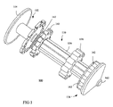
FIG. 3 is a side elevational view of the medical apparatus of FIG. 1.
FIG. 4 is a bottom view of the medical apparatus of FIG. 1.
FIG. 5 is a perspective view of the medical apparatus of FIG. 1;
FIG. 6 is another perspective view of the medical apparatus of FIG. 1
FIG. 7 is a fragmentary perspective view of the medical apparatus of FIG. 1;
FIG. 8 is another fragmentary perspective view of the medical apparatus of FIG. 1; and
FIG. 9 is a side view of another embodiment of a medical apparatus in accordance with the present invention;
DESCRIPTION OF PREFERRED EMBODIMENTS
Before explaining the preferred embodiments in detail, it should be noted that the invention is not limited in its application or use to the details of construction and arrangement of parts illustrated in the accompanying drawings and description, because the illustrative embodiments of the invention may be implemented or incorporated in other embodiments, variations and modifications, and may be practiced or carried out in various ways. Furthermore, unless otherwise indicated, the terms and expressions employed herein have been chosen for the purpose of describing the preferred embodiments of the present invention for the convenience of the reader and are not for the purpose of limitation.
Referring now to the drawings in detail, and particularly to FIGS. 1-3, a preferred embodiment of a medical apparatus 100 for filling a plurality of syringes is illustrated. The medical apparatus 100 allows multiple syringes to be easily and quickly filled at the same time. As a result, medical practitioners can reduce the amount of time spent for filling syringes, thereby reducing labor costs for the medical treatment.
The medical apparatus 100 also allows medical practitioners to fill a number of syringes with approximately the same amount of liquid. In addition, the medical apparatus fills multiple syringes without the need to insert the needle of the syringe in a sealed container of fluid, thereby avoiding damage to the syringe needles. Further, the medical apparatus can be used if additional syringes need to be quickly filled during a treatment of a patient. The medical apparatus is portable allowing it to be used in various treatment places in a medical facility and is less expensive than electronic automatic fillers.
The medical apparatus 100 of FIG. 1 is utilized to fill a plurality of conventional syringes 110. As shown in FIG. 5, the syringes 110 generally include a syringe barrel 112 and a syringe plunger 114 movably disposed within the syringe barrel 112. The syringe plunger 114 has a rubber bulb (not shown) on one end and a plunger head 116 on the other end. The syringe barrel 112 surrounds the lower portion of the syringe plunger 114. The syringe barrel 112 has a flange 118 at the upper end and a nozzle or tip 120 at the other end. The tip 120 can be attached to a needle once the syringes are filled with fluid. It should be recognized that the syringes are conventional and are not part of the present invention.
Referring now to FIGS. 1-3, the medical apparatus 100 includes a syringe holder apparatus 130, an actuator apparatus 132, and a fluid delivery apparatus or hub 134. The syringe holder apparatus 130 is configured to receive and hold a plurality of syringes to be filled with fluid. As shown in FIG. 5, the syringe holder apparatus 130 can hold up to ten (10) syringes, but it will be recognized that the syringe holder apparatus can be configured to hold any suitable number of syringes. The syringe holder apparatus 130 can be constructed from nylon, Teflon, polyurethane, or polyethylene. It will be recognized that the syringe holder apparatus 130 can be made from a variety of other materials including, for example, polypropylene, polyamide, polyethylenterephthalate, polyamide, other polymers and polycarbonates as well as other suitable forms of plastic.
The syringe holder apparatus 130 of the medical apparatus 100 generally includes an elongated member 136, first and second retaining members or collars 138 and 140, and a stop member 142. The elongated member 136 preferably has a substantially circular cross-section, but may have any suitable cross-section, such as a square or an elliptical cross-section. The elongated member 136 of the syringe holder apparatus 130 preferably includes a first end 143, a second end 144, and an aperture or bore 146 extending axially from its second end 144. The aperture 146 of the elongated member 136 allows the syringe holder apparatus 130 to be slidably mounted to the actuator apparatus 132 as further described below. The first end 143 of the elongated member 136 is configured to releasably mount to the fluid delivery apparatus 134.
The first and second retaining members 138 and 140 of the syringe holder apparatus 130 are mounted to the elongated member 136 at a pre-selected distance in order to securely hold the syringes during the filling process. The first retaining member 138 is mounted near the first end 143 of the elongated member 136 to releasably hold the upper portions of the syringe barrels, and the second retaining member 140 is attached near the second end 144 of the elongated member 136 to releasably hold the lower portions of the syringe barrels. As shown in FIG. 5, the syringe barrel 112 is disposed between the first and second retaining members 138 and 140. The spacing between the first and second retaining members 138 and 140 can be any suitable distance that is less than the length of the syringe barrel. It will be recognized that the syringe holder apparatus 130 may only have one retaining member or multiple retaining member to releasably hold the syringes to be filled.
The first and second retaining members 138 and 140 of the syringe holder apparatus 130 each have a plurality of recesses or slots 148 formed around its outer edge. The recesses 148 are adapted to receive and hold the syringe barrel. Preferably, the recesses 148 are sized to fit snugly around the syringe barrel, allowing a medical practitioner to easily and quickly attach or snap the syringe barrel to the syringe holder apparatus 130. It will be recognized that the recesses 148 can be configured to accommodate any suitable size syringe barrel and other mechanisms can be used to releasably hold the syringe barrels on the syringe holding member 130. For example, a clip or finger like member may be used to hold the syringe barrels onto the syringe holding member 130. The first and second retaining members 138 and 140 preferably have the same number of recesses that are in substantial alignment relative to the axis of the elongated member 136 of the syringe holding apparatus 130.
The stop member 142 of the syringe holder apparatus 130 is mounted to the second end 144 of the elongated member 136. The stop member preferably is cylindrically shaped, but can have any suitable shape. The stop member 142 is mounted to position the actuator apparatus to engage the plunger heads of the syringes as shown in FIG. 8 and as further described below.
As shown in FIG. 2, the actuator apparatus 132 of the medical apparatus 100 generally includes an elongated shaft 150, a driver or retraction member 152 and a hand grip or knob 154. The actuator apparatus 132 is slidably mounted to the syringe holder apparatus 130 to allow the plungers of the syringes mounted on the syringe holder apparatus 130 to be retracted or extended in order to cause the fluid to be drawn into the syringe barrels.
The elongated shaft 150 of the actuator apparatus 132 is slidably positioned in the aperture 146 of the syringe holder apparatus 130. The elongated shaft 150 can be moved axially in the aperture 146 of the syringe holder apparatus 130 to allow the actuator apparatus 132 to be moved relative to the syringe holder apparatus 130. The elongated shaft 150 may also be rotated in the aperture 146 of the syringe plunger apparatus to allow the driver member 152 to interlock with the syringe plunger as further described below.
The drive member 152 of the actuator apparatus 132 is configured and positioned to engage with the plunger heads of the syringes to move or retract the syringe plungers when the actuator apparatus 132 is withdrawn. As a result, fluid is drawn through the fluid delivery member and into the syringes. The driver member 152 includes a plurality of recesses 156 to receive the shaft of the syringe plunger. The recesses 156 preferably have a larger diameter than the shaft of the syringe plunger so that the recesses 156 loosely receive the shaft of the syringe plunger. However, the recesses 156 have a smaller diameter than plunger head of the syringe in order to engage the plunger head upon movement of the drive member 152.
As shown in FIGS. 1 and 7, the recesses 156 of the drive member 152 can be configured to interlock with the shaft of the syringe plunger when the actuator member is rotated clockwise. When the actuator apparatus 132 is moved in the direction of arrow A, the drive member 152 will engage the plunger head to move the syringe plunger and further movement will cause the extension of the syringe plunger. In an alternative embodiment shown in FIGS. 7 and 8, when the syringe barrel is mounted to the syringe holding member, the shaft of the syringe plungers 114 fit into the recesses of the retraction member and the plunger head 116 seats in an indentation or recess 160 of the drive member 152.
The hand grip 154 of the actuator apparatus 132 is substantially cylindrically shaped and is adapted to be grasped by a user or medical practitioner. It will be recognized that the hand grip 154 may be any suitable shape or size which allows it to be grasped by the user. The hand grip 154 allows a user to move the actuator apparatus 132 in an upwardly fashion to cause the drive member 152 to contact the plunger head of the syringe plunger. Once the drive member 152 contacts the plunger head and begins to move the syringe plunger, fluid to be drawn into the syringe barrel as further described below.
Referring now to FIGS. 1-3, the fluid delivery apparatus 134 of the medical apparatus 100 is releasably mounted to the first end 143 of the elongated member 136 of the syringe holder apparatus 130. The fluid delivery apparatus 134 allows fluid to be transported from a container of fluid into the syringe barrels that are mounted on the syringe holder apparatus 130. The fluid delivery apparatus 134 can be constructed from nylon, Teflon, polyurethane, or polyethylene. It will be recognized that the fluid delivery apparatus 134 can be made from a variety of other materials including, for example, polypropylene, polyamide, polyethylenterephthalate, polyamide, other polymers and polycarbonates as well as other suitable forms of plastic.
The fluid delivery apparatus 134 includes a bore 158, an inlet port 160 and a plurality of outlet ports 162. The bore 158 is configured so that the fluid delivery apparatus 134 can be releasably mounted to the first end 143 of the elongated member 136 of the syringe holder apparatus 132. The bore 158 can be any suitable shape to mate with the configuration of the first end 143 of the elongated member 136.
As shown in FIG. 1, the outlet ports 162 of the fluid delivery apparatus include a plurality of apertures formed in the upper surface of the fluid delivery apparatus 134. The apertures are sized to fit snugly around the tips of the syringe barrels. In an alternative embodiment shown in FIG. 9, the outlet ports 162 are formed by hollow sleeves 164 that extend outwardly from the upper end of the fluid delivery apparatus 134. The hollow sleeves 164 fit within the hole in the tip of the syringe barrel.
As shown in FIG. 6, a delivery conduit or pathway 166 extends from each outlet port 162 to the inlet port 160 of the fluid delivery apparatus 134. The delivery conduits 166 allow fluid to flow from the inlet port 160 to each of the outlet ports 162. A nozzle 170 or tube can be connected to the inlet port 160 to facilitate obtaining fluid.
The method of filling a plurality of syringes with the medical apparatus 100 of FIG. 1 will now be described. Initially, a medical practitioner places a plurality of syringes on the syringe holding apparatus 130 with the actuating apparatus 132 in its retracted or closed position. In this position, the plunger head will rest against the drive member 152 of the actuating apparatus 132.
A container having a desired fluid is opened or prepared, and a nozzle attached to the inlet port 160 of the medical apparatus 100 is placed in the fluid. It will be recognized that the inlet port 160 may be connected to a tube that can be inserted into the container.
Once the nozzle is placed in the fluid, the medical practitioner grasps the hand grip 154 of the actuator apparatus 132 and pulls it in an upward direction. As the actuator apparatus 132 moves upwardly, the drive member 152 of the actuator apparatus 132 engages the plunger heads of the syringe plungers causing the syringe plungers to be extended or retracted. As the syringe plungers are retracted, fluid is drawn through the inlet port and through the outlet ports via the delivery conduits. The fluid then travels through the tips of the syringes and into each of the syringe barrels.
Once the desired amount of liquid is drawn into each of the syringe barrel, the medical practitioner will stop retracting the actuator member 132. Once the syringes are filled, the medical practitioner can remove the syringes from the syringe holding member and use the syringes to inject fluid into a patient. This process can be repeated until the desired number of syringes are filled.
The medical apparatus and methods described above allow a plurality of syringes to be quickly and easily filled at the same time. As a result, medical practitioners can reduce the amount of time spent for filling syringes, thereby reducing labor costs for the medical treatment. The medical apparatus also fills multiple syringes without the need to insert the needle of the syringe in the sealed container, thereby avoiding damage to the syringe needles.
In addition, the medical apparatus can be used to quickly fill syringes if additional syringes need to be filled during a treatment of a patient. Further, the medical apparatus is portable allowing it to be used in various treatment places in a medical facility. The medical apparatus is also less expensive than electronic automatic syringe fillers.
Although the present invention has been described in detail by way of illustration and example, it should be understood that a wide range of changes and modifications can be made to the preferred embodiments described above without departing in any way from the scope and spirit of the invention. Thus, the described embodiments are to be considered in all respects only as illustrative and not restrictive, and the scope of the invention is, therefore, indicated by the appended claims rather than the foregoing description. All changes that come within the meaning and range of equivalency of the claims are to be embraced within their scope.

Claims (3)

1. A method for filling a plurality of syringes with a fluid, each of the syringes having a syringe barrel and a syringe plunger movably disposed within the syringe barrel, the method comprising the steps of:
mounting the plurality of syringes to an elongate syringe holding member, the elongate holding member having a central axial aperture;
connecting a fluid connecting member to the syringe holding member to mate with each tip of the syringe barrels;
placing an inlet port of the fluid connecting member in a fluid; and
moving an actuator apparatus slidably mounted within the central axial aperture of the syringe holding member to retract the syringe plungers to cause fluid to enter the syringe barrels.
2. The method of claim 1 farther comprising the step of moving the actuator apparatus until a desired amount of fluid is filled in the syringe barrel.
3. The method of claim 2 further comprising the step of removing the syringes from the syringe holding member.
US11/328,045 2006-01-09 2006-01-09 Syringe filling apparatus Expired - Fee Related US7571747B2 (en)

Priority Applications (2)

Application Number Priority Date Filing Date Title
US11/328,045 US7571747B2 (en) 2006-01-09 2006-01-09 Syringe filling apparatus
US12/411,177 US7882860B2 (en) 2006-01-09 2009-03-25 Syringe filling apparatus

Applications Claiming Priority (1)

Application Number Priority Date Filing Date Title
US11/328,045 US7571747B2 (en) 2006-01-09 2006-01-09 Syringe filling apparatus

Related Child Applications (1)

Application Number Title Priority Date Filing Date
US12/411,177 Continuation US7882860B2 (en) 2006-01-09 2009-03-25 Syringe filling apparatus

Publications (2)

Publication Number Publication Date
US20070161959A1 US20070161959A1 (en) 2007-07-12
US7571747B2 true US7571747B2 (en) 2009-08-11

Family

ID=38233630

Family Applications (2)

Application Number Title Priority Date Filing Date
US11/328,045 Expired - Fee Related US7571747B2 (en) 2006-01-09 2006-01-09 Syringe filling apparatus
US12/411,177 Expired - Fee Related US7882860B2 (en) 2006-01-09 2009-03-25 Syringe filling apparatus

Family Applications After (1)

Application Number Title Priority Date Filing Date
US12/411,177 Expired - Fee Related US7882860B2 (en) 2006-01-09 2009-03-25 Syringe filling apparatus

Country Status (1)

Country Link
US (2) US7571747B2 (en)

Cited By (2)

* Cited by examiner, † Cited by third party
Publication number Priority date Publication date Assignee Title
US8286671B1 (en) 2011-03-23 2012-10-16 Saverio Roberto Strangis Automated syringe filler and loading apparatus
US20190091396A1 (en) * 2013-03-15 2019-03-28 TS Medical, LLC Sterile transfer of fluid

Families Citing this family (3)

* Cited by examiner, † Cited by third party
Publication number Priority date Publication date Assignee Title
US8356644B2 (en) * 2009-08-07 2013-01-22 Medtronic Minimed, Inc. Transfer guard systems and methods
US20140124087A1 (en) * 2012-11-08 2014-05-08 Nordson Corporation Fluid delivery assemblies for withdrawing biomaterial fluid from a vial and for dispensing the biomaterial fluid, fluid control devices therefor, and related methods
US20220193341A1 (en) * 2020-12-22 2022-06-23 University Of Kansas Syringe splitting device

Citations (29)

* Cited by examiner, † Cited by third party
Publication number Priority date Publication date Assignee Title
US3498342A (en) * 1967-05-17 1970-03-03 Univ Of Queensland The Multiple droppers
US3662517A (en) 1970-04-08 1972-05-16 Sherwood Medical Ind Inc Syringe filling apparatus
US3734147A (en) 1971-03-17 1973-05-22 Sherwood Medical Ind Inc Manual syringe filling apparatus
US3807467A (en) * 1970-04-08 1974-04-30 Sherwood Medical Ind Inc Medicament filling unit
US3833030A (en) 1973-03-05 1974-09-03 E Flippo Device for withdrawing or adding fluids to hypodermic syringes
US3855868A (en) * 1972-02-10 1974-12-24 O Sudvaniemi Multiple pipette
US4489766A (en) 1982-09-13 1984-12-25 Montada Benjamin V Syringe filling device
US4501306A (en) 1982-11-09 1985-02-26 Collagen Corporation Automatic syringe filling system
US4842581A (en) * 1987-09-11 1989-06-27 Davis Richard C Medical lavage apparatus
US4846797A (en) 1985-05-14 1989-07-11 Intelligent Medicine, Inc. Syringe positioning device for enhancing fluid flow control
US4978336A (en) * 1987-09-29 1990-12-18 Hemaedics, Inc. Biological syringe system
US5179983A (en) 1991-05-03 1993-01-19 Block Medical, Inc. Apparatus for filling multiple reservoir infusion systems
US5253785A (en) * 1992-04-02 1993-10-19 Habley Medical Technology Corp. Variable proportion dispenser
US5329976A (en) 1991-12-09 1994-07-19 Habley Medical Technology Corporation Syringe-filling and medication mixing dispenser
US5385559A (en) 1993-12-20 1995-01-31 R. Jason Newsom Syringe filling and metering device
US5542760A (en) 1995-09-26 1996-08-06 Becton Dickinson And Company Syringe filler for mixing insulins
US5620422A (en) 1996-02-27 1997-04-15 Halbich; Frank Hypodermic syringe filling apparatus
US5647409A (en) 1995-04-04 1997-07-15 Allergan On-site syringe filling apparatus for viscoelastic materials, and corresponding method for on-site syringe filling
US5716345A (en) 1996-02-27 1998-02-10 Halbich; Frank Hypodermic syringe filling apparatuses and hypodermic syringe grasping apparatuses
US5844457A (en) 1996-11-25 1998-12-01 Eaton Corporation Electromagnetically operated electric switching apparatus
US5911252A (en) 1997-04-29 1999-06-15 Cassel; Douglas Automated syringe filling system for radiographic contrast agents and other injectable substances
US20010018937A1 (en) 1998-12-28 2001-09-06 Shigeru Nemoto Method and device for pre-filling a syringe with a contrast agent
US20020020459A1 (en) * 2000-08-10 2002-02-21 Baldwin Brian Eugene Method, system, and apparatus for handling, labeling, filling and capping syringes
EP1236644A1 (en) 2001-02-28 2002-09-04 Probitas Pharma, S.A. Apparatus for filling containers for pharmaceutical uses and the like
US6685693B1 (en) 2000-08-09 2004-02-03 J. Michael Casso Method of preparing a syringe for injection
WO2004108533A1 (en) 2003-06-06 2004-12-16 E-Z-Em, Inc. Peristaltic syringe filling station
US6915823B2 (en) 2002-12-03 2005-07-12 Forhealth Technologies, Inc. Automated apparatus and process for reconstitution and delivery of medication to an automated syringe preparation apparatus
US20060118199A1 (en) * 2004-09-06 2006-06-08 Jasco Corporation Syringe-pump driving apparatus
US20070186992A1 (en) * 2003-09-22 2007-08-16 Battelle Memorial Institute Container filling assembly

Family Cites Families (4)

* Cited by examiner, † Cited by third party
Publication number Priority date Publication date Assignee Title
JP2701900B2 (en) * 1988-12-20 1998-01-21 株式会社ニチリョー Multi pipette
US5116315A (en) * 1989-10-03 1992-05-26 Hemaedics, Inc. Biological syringe system
US5542934A (en) * 1995-06-02 1996-08-06 Silver; Richard M. Multiple carpule hypodermic syringe
US5884457A (en) * 1997-02-05 1999-03-23 Smithkline Beecham Corporation Method and apparatus for automatically producing a plurality of sterile liquid filled delivery devices

Patent Citations (30)

* Cited by examiner, † Cited by third party
Publication number Priority date Publication date Assignee Title
US3498342A (en) * 1967-05-17 1970-03-03 Univ Of Queensland The Multiple droppers
US3662517A (en) 1970-04-08 1972-05-16 Sherwood Medical Ind Inc Syringe filling apparatus
US3807467A (en) * 1970-04-08 1974-04-30 Sherwood Medical Ind Inc Medicament filling unit
US3734147A (en) 1971-03-17 1973-05-22 Sherwood Medical Ind Inc Manual syringe filling apparatus
US3855868A (en) * 1972-02-10 1974-12-24 O Sudvaniemi Multiple pipette
US3833030A (en) 1973-03-05 1974-09-03 E Flippo Device for withdrawing or adding fluids to hypodermic syringes
US4489766A (en) 1982-09-13 1984-12-25 Montada Benjamin V Syringe filling device
US4501306A (en) 1982-11-09 1985-02-26 Collagen Corporation Automatic syringe filling system
US4846797A (en) 1985-05-14 1989-07-11 Intelligent Medicine, Inc. Syringe positioning device for enhancing fluid flow control
US4842581A (en) * 1987-09-11 1989-06-27 Davis Richard C Medical lavage apparatus
US4978336A (en) * 1987-09-29 1990-12-18 Hemaedics, Inc. Biological syringe system
US5179983A (en) 1991-05-03 1993-01-19 Block Medical, Inc. Apparatus for filling multiple reservoir infusion systems
US5329976A (en) 1991-12-09 1994-07-19 Habley Medical Technology Corporation Syringe-filling and medication mixing dispenser
US5253785A (en) * 1992-04-02 1993-10-19 Habley Medical Technology Corp. Variable proportion dispenser
US5385559A (en) 1993-12-20 1995-01-31 R. Jason Newsom Syringe filling and metering device
US5647409A (en) 1995-04-04 1997-07-15 Allergan On-site syringe filling apparatus for viscoelastic materials, and corresponding method for on-site syringe filling
US5542760A (en) 1995-09-26 1996-08-06 Becton Dickinson And Company Syringe filler for mixing insulins
US5620422A (en) 1996-02-27 1997-04-15 Halbich; Frank Hypodermic syringe filling apparatus
US5716345A (en) 1996-02-27 1998-02-10 Halbich; Frank Hypodermic syringe filling apparatuses and hypodermic syringe grasping apparatuses
US5844457A (en) 1996-11-25 1998-12-01 Eaton Corporation Electromagnetically operated electric switching apparatus
US5911252A (en) 1997-04-29 1999-06-15 Cassel; Douglas Automated syringe filling system for radiographic contrast agents and other injectable substances
US20010018937A1 (en) 1998-12-28 2001-09-06 Shigeru Nemoto Method and device for pre-filling a syringe with a contrast agent
US6685693B1 (en) 2000-08-09 2004-02-03 J. Michael Casso Method of preparing a syringe for injection
US20020020459A1 (en) * 2000-08-10 2002-02-21 Baldwin Brian Eugene Method, system, and apparatus for handling, labeling, filling and capping syringes
EP1236644A1 (en) 2001-02-28 2002-09-04 Probitas Pharma, S.A. Apparatus for filling containers for pharmaceutical uses and the like
US7117901B2 (en) * 2001-02-28 2006-10-10 Probitas Pharma, S.A. Apparatus for filling containers for pharmaceutical uses and the like
US6915823B2 (en) 2002-12-03 2005-07-12 Forhealth Technologies, Inc. Automated apparatus and process for reconstitution and delivery of medication to an automated syringe preparation apparatus
WO2004108533A1 (en) 2003-06-06 2004-12-16 E-Z-Em, Inc. Peristaltic syringe filling station
US20070186992A1 (en) * 2003-09-22 2007-08-16 Battelle Memorial Institute Container filling assembly
US20060118199A1 (en) * 2004-09-06 2006-06-08 Jasco Corporation Syringe-pump driving apparatus

Cited By (6)

* Cited by examiner, † Cited by third party
Publication number Priority date Publication date Assignee Title
US8286671B1 (en) 2011-03-23 2012-10-16 Saverio Roberto Strangis Automated syringe filler and loading apparatus
US20190091396A1 (en) * 2013-03-15 2019-03-28 TS Medical, LLC Sterile transfer of fluid
US10549026B2 (en) * 2013-03-15 2020-02-04 TS Medical, LLC Sterile transfer of fluid
US20200147297A1 (en) * 2013-03-15 2020-05-14 TS Medical, LLC Sterile transfer of fluid
US11097047B2 (en) * 2013-03-15 2021-08-24 TS Medical, LLC Sterile transfer of fluid
US11793927B2 (en) 2013-03-15 2023-10-24 TS Medical, LLC Sterile transfer of fluid

Also Published As

Publication number Publication date
US7882860B2 (en) 2011-02-08
US20070161959A1 (en) 2007-07-12
US20090178726A1 (en) 2009-07-16

Similar Documents

Publication Publication Date Title
US8647324B2 (en) Catheter access and control device and method of using same
US7882860B2 (en) Syringe filling apparatus
US5968008A (en) Cannula with parallel channels and sliding sheath
JP2540026B2 (en) Chemical access assembly for vials and ampoules
US6726658B2 (en) Safety IV catheter infusion device
US20040064098A1 (en) Hypodermic needle and fluid injection device
US11305060B2 (en) Actuator and device for synchronized injection and aspiration
US20170290985A1 (en) Revolving multi-cartridge hypodermic syringe and method of use
AU2020202472B2 (en) Caps for integrated fill and inject of safety needle devices
US20040186433A1 (en) Safety IV catheter infusion device
EP3254717A1 (en) Syringe and method for dispensing a liquid
JP3941088B2 (en) Chemical injection device
US10376656B2 (en) Side-angle decapping of pre-filled syringe
US20230256176A1 (en) Adapter and injection syringe
JP5597199B2 (en) Device for injecting liquid into the body of a patient or the like
CN115052647A (en) Primary container assembly with integrated fluid passageway

Legal Events

Date Code Title Description
STCF Information on status: patent grant

Free format text: PATENTED CASE

REMI Maintenance fee reminder mailed
FPAY Fee payment

Year of fee payment: 4

SULP Surcharge for late payment
FEPP Fee payment procedure

Free format text: PAYOR NUMBER ASSIGNED (ORIGINAL EVENT CODE: ASPN); ENTITY STATUS OF PATENT OWNER: SMALL ENTITY

FPAY Fee payment

Year of fee payment: 8

FEPP Fee payment procedure

Free format text: MAINTENANCE FEE REMINDER MAILED (ORIGINAL EVENT CODE: REM.); ENTITY STATUS OF PATENT OWNER: SMALL ENTITY

LAPS Lapse for failure to pay maintenance fees

Free format text: PATENT EXPIRED FOR FAILURE TO PAY MAINTENANCE FEES (ORIGINAL EVENT CODE: EXP.); ENTITY STATUS OF PATENT OWNER: SMALL ENTITY

STCH Information on status: patent discontinuation

Free format text: PATENT EXPIRED DUE TO NONPAYMENT OF MAINTENANCE FEES UNDER 37 CFR 1.362

FP Lapsed due to failure to pay maintenance fee

Effective date: 20210811