US7561584B1 - Implementation of a graph property in a switching fabric for fast networking - Google Patents
Implementation of a graph property in a switching fabric for fast networking Download PDFInfo
- Publication number
- US7561584B1 US7561584B1 US11/270,010 US27001005A US7561584B1 US 7561584 B1 US7561584 B1 US 7561584B1 US 27001005 A US27001005 A US 27001005A US 7561584 B1 US7561584 B1 US 7561584B1
- Authority
- US
- United States
- Prior art keywords
- dag
- switching fabric
- graphs
- sub
- never
- Prior art date
- Legal status (The legal status is an assumption and is not a legal conclusion. Google has not performed a legal analysis and makes no representation as to the accuracy of the status listed.)
- Active, expires
Links
Images


Classifications
-
- H—ELECTRICITY
- H04—ELECTRIC COMMUNICATION TECHNIQUE
- H04L—TRANSMISSION OF DIGITAL INFORMATION, e.g. TELEGRAPHIC COMMUNICATION
- H04L49/00—Packet switching elements
- H04L49/25—Routing or path finding in a switch fabric
-
- H—ELECTRICITY
- H04—ELECTRIC COMMUNICATION TECHNIQUE
- H04L—TRANSMISSION OF DIGITAL INFORMATION, e.g. TELEGRAPHIC COMMUNICATION
- H04L49/00—Packet switching elements
- H04L49/10—Packet switching elements characterised by the switching fabric construction
Definitions
- a switching fabric is a network of interconnected integrated circuits that operate to switch (i.e., route) data packets from input ports to output ports in a single network system.
- switching fabrics switch data packets between central processing units (CPUs), memory units, and input/output (I/O) units of single network systems.
- data is source routed within the switching fabric using an encoding scheme that allows the switches to determine which way to route data.
- an encoding scheme that allows the switches to determine which way to route data.
- all turns are possible from any one location in the switching fabric. That is, data can be routed in any direction from each switching point in the switching fabric.
- the switching fabric arbitrates between traffic destined for the same output port.
- resources i.e., switches in the switching fabric, links between switches, buffers along the lines, etc.
- are occupied by data packets in a wormhole fashion i.e., a packet travels in successive pieces and thus may occupy several resources
- data packets routed in such a 2D switching fabric may deadlock.
- two (or more) messages may mutually block each other if they block the progression of each other simultaneously.
- Deadlock may also occur if messages double back on themselves (i.e., get stuck in an infinite waiting loop).
- provisions against deadlocking in switching fabrics involve the use of buffers, and/or control logic or software to delay or regulate or constrain the route that data takes from a particular source to a particular destination.
- buffers in the switching fabric can be used to cache particular data routing patterns temporarily so that packets being routed through the same switching point do not block each other.
- the invention in general, in one aspect, relates to a system, including at least one central processing unit, at least one memory unit, and a plurality of integrated circuits that form a switching fabric configured to propagate data packets between the at least one central processing unit and the at least one memory unit, wherein the switching fabric is constructed using at least two directed acyclic graph (DAG) networks.
- DAG directed acyclic graph
- the invention relates to a method for constructing a switching fabric, comprising obtaining at least two sub-graphs comprising a deadlock-free property in an existing switching fabric, wherein the at least two sub-graphs are directed acyclic graphs (DAGs), combining the at least two sub-graphs to obtain an initially connected switching fabric, adding a multiplexer to each input of the initially connected switching fabric, wherein the multiplexer allows the selection of one of the at least two sub-graphs, adding a demultiplexer to each output of the initially connected switching fabric to obtain a fully-connected switching fabric, wherein the demultiplexer allows the selection of one of the at least two sub-graphs, wherein the fully-connected switching fabric comprises the deadlock-free property.
- DAGs directed acyclic graphs
- the invention relates to a computer readable medium for constructing a switching fabric comprising software instructions to obtain at least two sub-graphs comprising a deadlock-free property in an existing switching fabric, wherein the at least two sub-graphs are directed acyclic graphs (DAGs), combine the at least two sub-graphs to obtain an initially connected switching fabric, add a multiplexer to each input of the initially connected switching fabric, wherein the multiplexer allows the selection of one of the at least two sub-graphs, and add a demultiplexer to each output of the initially connected switching fabric to obtain a fully-connected switching fabric, wherein the demultiplexer allows the selection of one of the at least two sub-graphs, and wherein the fully-connected switching fabric comprises the deadlock-free property.
- DAGs directed acyclic graphs
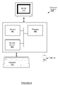
- FIG. 1 shows a system in accordance with an embodiment of the present invention.
- FIG. 2 shows integrated circuits that form a switching fabric in accordance with an embodiment of the present invention.
- FIG. 3 shows a not-south never-this-direction DAG in accordance with one, embodiment of the invention.
- FIG. 4 shows a dependency graph for a never-this-direction DAG in accordance with an embodiment of the present invention.
- FIGS. 5A and 5B show never this direction DAGs and a combination of the never-this-direction DAGs to form a switching fabric in accordance with one embodiment of the invention.
- FIG. 6 shows interconnected integrated circuits in accordance with one embodiment of the invention.
- FIG. 7 shows a flow chart for designing a switching fabric in accordance with one embodiment of the invention.
- FIG. 8 shows a flow chart for routing data using a switching fabric in accordance with one embodiment of the invention.
- FIG. 9 shows a computer system in accordance with one embodiment of the invention.
- embodiments of the invention relate to designing switching fabrics with restricted routing such that an inherent property of the switching fabric is ensured.
- embodiments of the invention relate to designing a deadlock-free switching fabric using graph theory to ensure that the switching fabric is inherently deadlock-free.
- embodiments of the invention relate to designing a deadlock free switching fabric using directed acyclic graphs (DAGs).
- DAGs directed acyclic graphs
- FIG. 1 shows a system in accordance with one embodiment of the invention. Specifically, FIG. 1 shows the system divided into a plurality of computing modules (i.e., module ( 100 )).
- a module ( 100 ) includes one or more central processing units (CPUs) ( 102 ), one or more memory units ( 104 ) (e.g., cache memory, memory controllers), I/O Controllers ( 108 ) for communicating with devices outside of the module, and a switching “fabric” ( 106 ) for switching data packets between, among other things, (i) the CPUs ( 102 ) and the memory units ( 104 ) and (ii) between module ( 100 ) and another module (not shown).
- the CPUs ( 102 ), memory units ( 104 ), and I/O Controllers ( 108 ) are all connected to the switching fabric ( 106 ) in the same manner so that each component can exchange data and communicate through the switching fabric ( 106 ).
- a switching fabric may be formed of a plurality of individual integrated circuits (ICs).
- ICs integrated circuits
- embodiments of the present invention relate to a technique for designing one or more integrated circuits for a switching fabric, where the switching capabilities in the integrated circuits include an inherent deadlock-free property that prevents data from deadlocking when being routed through the switching fabric.
- any device e.g., storage disks, long distance memory access, etc.
- network e.g., IP network, wireless network, etc.
- a storage disk may be connected to the memory units.
- devices or units may also be connected on any edge of the switching fabric ( 106 ) (described below in FIG. 3 ), and not only to the periphery of the switching fabric ( 106 ).
- FIG. 2 shows a switching fabric ( 110 ) in accordance with an embodiment of the invention.
- the switching fabric ( 110 ) of FIG. 2 is formed of individual integrated circuits (ICs) (e.g., 112 , 114 , 116 , 118 , 120 , 122 , 124 , 125 , 126 , 128 , 130 , 132 , 134 , 136 , 138 , 140 , 142 , 144 , 146 , 148 ).
- ICs integrated circuits
- the integrated circuits include regions configured for “proximity communication.” Proximity communication is based on the observation that fast, low-cost communication is possible over short distances.
- Integrated circuits that are positioned for proximity communication are arranged such that transmitting and receiving circuits in the integrated circuits are aligned with only microns of distance between them (i.e., interconnecting ICs via proximity communication requires the inputs and outputs of the ICs to be aligned).
- switches are implemented on the ICs (e.g., 112 , 114 , 116 , 118 , 120 , 122 , 124 , 125 , 126 , 128 , 130 , 132 , 134 , 136 , 138 , 140 , 142 , 144 , 146 , 148 ) in a manner that allows the ICs to be interconnected via proximity communication (or some other media) when the ICs are physically close enough.
- the alignment of the inputs and outputs of the interconnected ICs is obtained using symmetrical 2-dimensional DAGs (discussed below).
- a group of ICs interconnected in such a manner forms a module (such as module ( 100 ) shown in FIG. 1 ).
- one embodiment of the invention uses proximity communication between the integrated circuits of a switching fabric, there may be several other methods for communication between integrated circuits in a switching fabric.
- integrated circuits may be connected via an electrical bus using fast, high density, low energy communication wires.
- fast, high density, low energy communication wires may be any type of overlapping in the layout of the individual integrated circuits.
- the integrated circuits may overlap in each of the four corners.
- the present invention relates to constructing switching fabrics with an inherent deadlock-free property.
- constructing a switching fabric using embodiments of the present invention may be thought of as breaking up network communication lines of a certain physical width into many narrower, parallel lines that restrict the directions that data is permitted to be routed from a particular source to one or more destinations.
- space division multiplexing is applied to a switching fabric (i.e., to the ICs in a switching fabric) that allows data to travel in all directions from all points of the switching fabric such that the switching fabric is divided into smaller, limited directional switching fabrics that work together to route data from source to destination.
- a bidirectional line may be divided into two directed lines.
- a bidirectional network of width w where all the lines switch data in all directions at each switching point, may be divided into smaller networks of width w/8, where each network is built around unidirectional lines that include restricted switching possibilities at each switching point.
- a switching fabric with an inherent deadlock-free property is constructed using a collection of directed acyclic graphs (DAGs).
- a DAG is a directed graph that contains no possibility of cycles. That is, a DAG cannot be traced such that data leaves source A (where a source may be a vertex or an edge on the DAG) and subsequently comes back to source A by forming a cycle.
- each integrated circuit shown in FIG. 2 may be mapped onto a separate independent DAG network (discussed below).
- the DAG network associated with each IC in the system may be symmetrical. In this case, the switching fabric constructed from DAG networks associated with one IC may be duplicated for other interconnected ICs to obtain the switching fabric for an entire system/device.
- Quadrant DAGs are DAGs that allow switching only in two successive directions. Said another way, quadrant DAGs follow the north-east, north-west, south-east, or south-west quadrants. Notice that several turns are not possible in each of these DAGs because data is forbidden to travel in two directions.
- never-this-direction DAGs where turns in all but one direction are possible, may be used to construct switching fabrics.
- a collection of (quadrant or never-this-direction) DAGs is several (quadrant or never-this-direction) DAGs representing the network for each chip or integrated circuit of the system put together to build a switching fabric for the entire system.
- FIG. 3 shows an example of a never-this-direction DAG in accordance with one embodiment of the invention.
- Never-this-direction DAGs follow a not-south, a not-north, a not-east, or a not-west policy. In this manner, U-turns within the switching fabric are not possible.
- the graph shown in FIG. 3 employs a not-south policy, as indicated by the lack of an arrow in the south direction in the graph.
- north, east, and west turns are possible, but because data is not permitted to travel in the south direction, it can easily be seen that data cannot loop back upon itself.
- each edge i.e., A, B, C, D, E, F, G, H, I, J, K
- An edge is defined as a portion of the data path between entry points (e.g., A, B, F), exit points (e.g., C, E, G), and portions of the graph that allow data to change directions (i.e., turn) (H, I, J, K).
- entry points e.g., A, B, F
- exit points e.g., C, E, G
- portions of the graph that allow data to change directions i.e., turn
- edges may be used to determine a dependency graph associated with a DAG, depending on how complicated the DAG network may be.
- devices and/or units may be connected to any edge of a switching fabric network. For example, in FIG. 3 , a device may be connected to edge A, B, C, etc.
- a switching fabric is constructed by mapping a portion of the switching fabric onto a DAG network, such as the never-this-direction DAG network shown in FIG. 3 .
- a portion of a switching fabric may also be mapped onto a quadrant DAG network.
- a combination of independent DAGs are used to design a switching fabric for a system. More particularly, each integrated circuit in a device or system may be mapped onto a DAG network. The DAG networks for each integrated circuit may then be combined to obtain a deadlock-free switching fabric for the entire system or for one or more devices in the system (discussed below in FIGS. 5A and 5B ).
- a combination of independent DAGs provides the same connectivity/switching capacity as the original graph, in addition to providing the useful property of avoiding deadlocks, with only the cost of an initial multiplexing step to switch onto a DAG of a switching fabric that is able to route data to the intended destination.
- deadlocks are inherently not possible because, as can be easily shown, the graph formed by tracing the dependencies of the DAG network (described below) is also a DAG.
- the present invention focuses on constructing a switching fabric with an inherent deadlock-free property, the present invention may also be used to apply graph theory to design switching fabrics with other inherent properties for fast network, such as edge or vertex load balancing, reducing the diameter, path redundancy, etc.
- FIG. 1 i.e., CPUs, memory units, I/O units
- FIG. 3 the components shown in FIG. 1 (i.e., CPUs, memory units, I/O units) may be connected to any edge shown in FIG. 3 , as long as the connection of such units does not introduced any cyclic dependencies in the dependency graph of FIG. 4 (described below).
- FIG. 4 shows a dependency directed graph corresponding to the never-this-direction DAG shown in FIG. 3 in accordance with one embodiment of the invention.
- each edge i.e., A, B, C, D, E, F, G, H, I, J, K
- the dependency graph is formed by connecting the edges (i.e., the open circles representing the edges) between which data is permitted to travel.
- edges i.e., the open circles representing the edges
- data entering edge A can be routed to edge H (in order to reach edge C in an westbound direction) or may be routed directly vertically (north) and exit via edge G.
- edge A is directly connected to edges H and G
- edge H is connected to edge C.
- data entering edge B may continue west to edge C or turn in a northbound direction toward edge K.
- FIG. 5A shows four independent never-this-direction DAGs (i.e., 500 , 502 , 504 , 506 ) in accordance with one embodiment of the invention.
- never-this direction DAG ( 500 ) employs a not-north policy
- never-this direction DAG ( 502 ) employs a not-south policy
- never-this direction DAG ( 504 ) employs a not-west policy
- never-this direction DAG ( 506 ) employs a not-east policy.
- each switching network is mapped onto a 2D DAG grid. In the case shown in FIG.
- FIG. 5B shows an example of combining never-this-direction DAGs in an IC ( 520 ) to provide switching capabilities within the IC ( 520 ) in accordance with one embodiment of the invention.
- FIG. 5B combines the four independent never-this-direction DAG networks of FIG. 5A on one IC ( 520 ).
- lines 1 , 2 , and 12 is a not-north never-this-direction DAG (i.e., 500 in FIG. 5A ), and lines 3 , 4 , and 11 make up a not-south never-this-direction DAG (i.e., 502 in FIG. 5A ).
- lines 5 , 9 , and 10 represent a not-east never-this-direction DAG (i.e., 506 in FIG. 5A ), and lines 6 , 7 , and 8 represent a not-west never-this-direction DAG (i.e., 504 in FIG. 5A ).
- each switching area i.e., Switching Area A ( 510 ), Switching Area B ( 512 ), Switching Area C ( 516 ), Switching Area D ( 514 ) covers the area in which turns are possible in a particular never-this-direction DAG.
- the switching fabric of FIG. 5B may be duplicated on all the interconnected ICs in the system.
- the switching fabric shown in FIG. 5B may be duplicated on all the ICs interconnected in FIG. 2 .
- all the outputs of the switching fabric correspond to inputs of the adjacent switching fabric associated with an interconnected IC (i.e., the outputs of the switching fabric correspond to inputs of the neighbor switching fabric).
- a fully connected switch is constructed from a collection of simple switching ICs with the initial bandwidth distributed in 6 times w/6 unidirectional lines belonging to four completely independent DAGs.
- when one switching fabric is symmetrically duplicated in this manner all the connections of each switching fabric follow the DAG construction.
- not-north never-this-direction DAGs connect to other not-north never-this direction DAGs
- not-east never-this-direction DAGs connect to other not-east never-this-direction DAGs, etc.
- all the DAGs are of the same type (i.e., never-this-direction DAGs, quadrant DAGs, etc.).
- a specific one of the several DAG networks that make up the switching fabric within the IC may be chosen to route data, depending on which direction the data needs to be routed to reach a desired destination. For example, if data enters on line 2 , then data may be routed south on line 12 , or data may continue westbound to another IC. Thus, if the destination of data is located in a south or west direction, then the not-north DAG network represented by switching area A ( 510 ) may be chosen. Alternatively, if the destination of data entering the switching fabric of FIG. 5B is located north, then the data may enter using line 3 and be routed northbound on line 11 via switching area B ( 512 ).
- switching fabric of FIG. 5B may be combined with other switching devices to form larger switching fabrics that are associated with multiple devices of a system. Further, those skilled in the art will appreciate that quadrant DAGs or any other type of DAG may also be combined to form a “fully connected” switching fabric as shown in FIG. 5B .
- FIG. 6 shows an example of interconnected integrated circuits (ICs) (i.e., 600 , 602 , 604 , 606 ) in accordance with one embodiment of the invention. More specifically, FIG. 6 shows four ICs (i.e., 600 , 602 , 604 , 606 ) mapped onto a never-this-direction DAG that are interconnected in a switching fabric. For example, the ICs shown in FIG. 6 may be four of the ICs positioned side by side in FIG. 2 . In one embodiment of the invention, the ICs (i.e., 600 , 602 , 604 , 606 ) are interconnected via proximity communication.
- ICs i.e., 600 , 602 , 604 , 606
- ICs may also be interconnected using other methods of connection, e.g., electrical wires connected across a bus, etc.
- the never-this-direction DAG shown in FIG. 6 is a not-west never-this-direction DAG, as indicated by the lack of an arrow in the west direction.
- data entering IC ( 600 ) may be routed eastward to IC ( 602 ), southbound to IC ( 604 ) or south and then east to IC ( 606 ).
- ICs ( 602 , 604 , or 606 ) are not the destination for the data, then data may exit one of the ICs ( 602 , 604 , or 606 ) onto another DAG sub-graph that allows the data to be routed to a final destination.
- data entering IC ( 606 ) can continue north to IC ( 602 ) or exist one of IC ( 602 ) or IC ( 606 ) and continue on a not-west DAG sub-graph to a final destination.
- module-to-module interconnection is also performed using DAG network properties, so that the deadlock-free property is extended to the construction of the entire system.
- the DAG deadlock-free property is inherently present when multiple never-this-direction DAGs are combined (e.g., as in FIG. 6 ) due to the following conditions: (1) data is not permitted to loopback from the east direction using the west direction; and (2) if an attempt is made to loopback from north to south or from south to north, data must be routed eastbound for one hop, where the first condition applies, such that loopback on the same DAG network is impossible.
- FIG. 7 shows a flow chart for constructing a switching fabric network in accordance with one embodiment of the invention.
- the network graph of a switching fabric that ensures the deadlock-free property using software is obtained (Step 700 ).
- the network graph of an existing switching fabric that implements the deadlock-free property via software is obtained.
- the sub-graphs i.e., the individual networks within the switching fabric
- the sub-graphs that include deadlock-free property inherently built-in are determined (Step 702 ).
- the DAG sub-graphs within the switching fabric are determined.
- the sub-graphs correspond to output ports to exit sources and to input ports to input destinations of one or more integrated circuits in the system.
- Step 702 may be performed using graph theory well known in the art.
- the sub-graphs are combined to obtain the initial connections between sources and destinations in the switching fabric (Step 704 ).
- a multiplexer is added to each graph input, which allows the selection of a particular DAG sub-graph from each input of the switching fabric (Step 706 ).
- demultiplexers are added to graph outputs, which allow the selection of particular sub-graphs from each output of the switching fabric (Step 708 ).
- multiplexers and demultiplexers are added to the switching fabric when devices are connected to the switching fabric because the devices may need to access a location within the switching fabric from any direction.
- FIG. 8 shows a flow chart for routing data using a switching fabric constructed with a collection of DAG networks in accordance with one embodiment of the invention.
- the process of FIG. 8 performs all the switching decisions at the source, and places the instructions for routing of data in the header of the data stream so that each switch encountered from the source to the destination simply decodes the header bits that dictate where the data should be routed.
- data may also be routed such that the switches make decisions about where to route the data on-the-fly.
- the command for routing data may also be external or dynamic as long as the initial multiplexing choice performed to choose the appropriate DAG network is correct.
- a DAG network is selected that allows the data to reach a particular destination without encountering any deadlocks (Step 800 ).
- a specific DAG sub-graph in the switching fabric that connects the source to the desired destination is selected. For example, if the switching fabric is constructed using never-this-direction DAG networks, then particular turns are not possible at each switching area. Thus, the correct switching network needs to be selected from the source such that the turns necessary to reach the desired destination are permitted.
- the route i.e., the switching commands
- bit sequence is constructed to be used as a command for each switching point in the switching fabric (Step 804 ).
- the bit sequence is placed in the headers of the packets being routed.
- the data is routed from the source to the destination using the bit sequence (Step 806 ).
- the bit sequence may use two bits per command.
- the bit sequence 00 may indicate that data is to be routed straight through the chip and onto the next chip.
- the bit sequence 00 may control at least two or as many as three switches, depending on the design of the switching fabric.
- the bit sequence 01 may indicate a left turn, in which case only the first switch encountered may be controlled with this bit sequence.
- the bit sequence 10 may represent “this chip,” indicating that the payload of the data is to be delivered to the memory of the current chip, in which case up to five switches may be controlled using this one two bit sequence.
- the last combination, 11, may be used to signify the end of the word.
- bits of the bit sequence are consumed, whether consumption is based on data exiting the current chip or deliverance of the payload to memory, the bits may be shifted so that further commands are available for the next switch encountered in the switching fabric.
- encoding schemes may exist for use to route data in a deadlock-free switching fabric.
- data may be routed using one-bit encoding schemes, where 0 indicates that data is to be routed straight, and 1 indicates that data is to turn.
- the routing command may be inside the header of the packet, external to the packet, or a combination of both.
- a networked computer system ( 900 ) includes a processor ( 902 ), associated memory ( 904 ), a storage device ( 906 ), and numerous other elements and functionalities typical of today's computers (not shown).
- the networked computer ( 900 ) may also include input means, such as a keyboard ( 908 ) and a mouse ( 910 ), and output means, such as a monitor ( 912 ).
- the networked computer system ( 900 ) is connected to a local area network (LAN) or a wide area network via a network interface connection (not shown).
- these input and output means may take other forms.
- one or more elements of the aforementioned computer ( 900 ) may be located at a remote location and connected to the other elements over a network.
- software instructions to perform embodiments of the invention may be stored on a computer readable medium such as a compact disc (CD), a diskette, a tape, a file, or any other computer readable storage device.
- Embodiments of the invention provide a method for constructing switching fabrics with an inherent deadlock-free property built into the network. By reducing the width of the network lines, some space is traded to produce multiple independent networks that avoid deadlock. This avoids the burden on switching algorithms to avoid deadlock when routing data. Thus, simple switching algorithms can be used to route data. Further, in a well-balanced, symmetric network, overall bandwidth is not affected because of the sum of the smaller, multiple independent network lines equals the bandwidth of the original network line.
Landscapes
- Engineering & Computer Science (AREA)
- Computer Networks & Wireless Communication (AREA)
- Signal Processing (AREA)
- Multi Processors (AREA)
Abstract
Description
Claims (15)
Priority Applications (1)
| Application Number | Priority Date | Filing Date | Title |
|---|---|---|---|
| US11/270,010 US7561584B1 (en) | 2005-11-09 | 2005-11-09 | Implementation of a graph property in a switching fabric for fast networking |
Applications Claiming Priority (1)
| Application Number | Priority Date | Filing Date | Title |
|---|---|---|---|
| US11/270,010 US7561584B1 (en) | 2005-11-09 | 2005-11-09 | Implementation of a graph property in a switching fabric for fast networking |
Publications (1)
| Publication Number | Publication Date |
|---|---|
| US7561584B1 true US7561584B1 (en) | 2009-07-14 |
Family
ID=40846325
Family Applications (1)
| Application Number | Title | Priority Date | Filing Date |
|---|---|---|---|
| US11/270,010 Active 2027-05-25 US7561584B1 (en) | 2005-11-09 | 2005-11-09 | Implementation of a graph property in a switching fabric for fast networking |
Country Status (1)
| Country | Link |
|---|---|
| US (1) | US7561584B1 (en) |
Cited By (4)
| Publication number | Priority date | Publication date | Assignee | Title |
|---|---|---|---|---|
| US10089761B2 (en) | 2016-04-29 | 2018-10-02 | Hewlett Packard Enterprise Development Lp | Graph processing using a shared memory |
| US20190121388A1 (en) * | 2017-10-20 | 2019-04-25 | Graphcore Limited | Compiler method |
| KR20190044548A (en) * | 2017-10-20 | 2019-04-30 | 그래프코어 리미티드 | Direction indicator |
| RU2815332C1 (en) * | 2023-02-14 | 2024-03-13 | Федеральное государственное бюджетное учреждение науки Институт проблем управления им. В.А. Трапезникова Российской академии наук | Method for constructing switched control networks with quasi-complete digraph topology |
Citations (2)
| Publication number | Priority date | Publication date | Assignee | Title |
|---|---|---|---|---|
| WO2005026964A2 (en) * | 2003-09-04 | 2005-03-24 | Koninklijke Philips Electronics N.V. | Data processing system |
| US20070003055A1 (en) * | 2005-06-23 | 2007-01-04 | Agere Systems, Inc. | Single-transformer digital isolation barrier |
-
2005
- 2005-11-09 US US11/270,010 patent/US7561584B1/en active Active
Patent Citations (2)
| Publication number | Priority date | Publication date | Assignee | Title |
|---|---|---|---|---|
| WO2005026964A2 (en) * | 2003-09-04 | 2005-03-24 | Koninklijke Philips Electronics N.V. | Data processing system |
| US20070003055A1 (en) * | 2005-06-23 | 2007-01-04 | Agere Systems, Inc. | Single-transformer digital isolation barrier |
Cited By (11)
| Publication number | Priority date | Publication date | Assignee | Title |
|---|---|---|---|---|
| US10089761B2 (en) | 2016-04-29 | 2018-10-02 | Hewlett Packard Enterprise Development Lp | Graph processing using a shared memory |
| US20190121388A1 (en) * | 2017-10-20 | 2019-04-25 | Graphcore Limited | Compiler method |
| KR20190044548A (en) * | 2017-10-20 | 2019-04-30 | 그래프코어 리미티드 | Direction indicator |
| GB2569272A (en) * | 2017-10-20 | 2019-06-19 | Graphcore Ltd | Direction indicator |
| US10360175B2 (en) * | 2017-10-20 | 2019-07-23 | Graphcore Limited | Direction indicator |
| US20190310963A1 (en) * | 2017-10-20 | 2019-10-10 | Graphcore Limited | Direction indicator |
| TWI678088B (en) * | 2017-10-20 | 2019-11-21 | 英商葛夫科有限公司 | Direction indicator |
| GB2569272B (en) * | 2017-10-20 | 2020-05-27 | Graphcore Ltd | Direction indicator |
| US10802536B2 (en) * | 2017-10-20 | 2020-10-13 | Graphcore Limited | Compiler method |
| US10817459B2 (en) * | 2017-10-20 | 2020-10-27 | Graphcore Limited | Direction indicator |
| RU2815332C1 (en) * | 2023-02-14 | 2024-03-13 | Федеральное государственное бюджетное учреждение науки Институт проблем управления им. В.А. Трапезникова Российской академии наук | Method for constructing switched control networks with quasi-complete digraph topology |
Similar Documents
| Publication | Publication Date | Title |
|---|---|---|
| US10838787B2 (en) | Processing system with interspersed processors with multi-layer interconnect | |
| US8601423B1 (en) | Asymmetric mesh NoC topologies | |
| US8825986B2 (en) | Switches and a network of switches | |
| Hollstein et al. | Mixed-criticality NoC partitioning based on the NoCDepend dependability technique | |
| US7561584B1 (en) | Implementation of a graph property in a switching fabric for fast networking | |
| Ouyang et al. | Fabdb: a low-latency fault-tolerant architecture based on dynamic bypass for network-on-chip: Y. Ouyang et al. | |
| Hou et al. | HOFT: A New Fault-Tolerant Routing Algorithm for Network-on-Chip | |
| Amaresh et al. | Performance Analysis of Data Communication Using Hybrid NoC for Low Latency and High Throughput on FPGA | |
| Umamaheswari et al. | Dynamic buffer management to improve the performance of fault tolerance adaptive network-on-chip applications | |
| Singh et al. | Simulation of Optimum topology and Routing Algorithm for 3D Network on Chip |
Legal Events
| Date | Code | Title | Description |
|---|---|---|---|
| AS | Assignment |
Owner name: SUN MICROSYSTEMS, INC., CALIFORNIA Free format text: ASSIGNMENT OF ASSIGNORS INTEREST;ASSIGNORS:COHEN, DANNY;SUTHERLAND, IVAN;REEL/FRAME:017214/0607;SIGNING DATES FROM 20051027 TO 20051103 Owner name: SUN MICROSYSTEMS FRANCE S.A., FRANCE Free format text: ASSIGNMENT OF ASSIGNORS INTEREST;ASSIGNORS:TOURANCHEAU, BERNARD;GOURAUD, HENRI;REEL/FRAME:017786/0699 Effective date: 20051020 |
|
| AS | Assignment |
Owner name: SUN MICROSYSTEMS, INC., CALIFORNIA Free format text: ASSIGNMENT OF ASSIGNORS INTEREST;ASSIGNOR:SUN MICROSYSTEMS FRANCE S.A.;REEL/FRAME:018004/0926 Effective date: 20060719 |
|
| STCF | Information on status: patent grant |
Free format text: PATENTED CASE |
|
| FPAY | Fee payment |
Year of fee payment: 4 |
|
| AS | Assignment |
Owner name: ORACLE AMERICA, INC., CALIFORNIA Free format text: MERGER AND CHANGE OF NAME;ASSIGNORS:ORACLE USA, INC.;SUN MICROSYSTEMS, INC.;ORACLE AMERICA, INC.;REEL/FRAME:037304/0183 Effective date: 20100212 |
|
| FPAY | Fee payment |
Year of fee payment: 8 |
|
| MAFP | Maintenance fee payment |
Free format text: PAYMENT OF MAINTENANCE FEE, 12TH YEAR, LARGE ENTITY (ORIGINAL EVENT CODE: M1553); ENTITY STATUS OF PATENT OWNER: LARGE ENTITY Year of fee payment: 12 |