US7537508B1 - Carbide model rocketry system - Google Patents
Carbide model rocketry system Download PDFInfo
- Publication number
- US7537508B1 US7537508B1 US11/391,701 US39170106A US7537508B1 US 7537508 B1 US7537508 B1 US 7537508B1 US 39170106 A US39170106 A US 39170106A US 7537508 B1 US7537508 B1 US 7537508B1
- Authority
- US
- United States
- Prior art keywords
- rocket
- tube
- launch
- conductive
- spark
- Prior art date
- Legal status (The legal status is an assumption and is not a legal conclusion. Google has not performed a legal analysis and makes no representation as to the accuracy of the status listed.)
- Expired - Fee Related, expires
Links
- 230000008878 coupling Effects 0.000 claims abstract description 61
- 238000010168 coupling process Methods 0.000 claims abstract description 61
- 238000005859 coupling reaction Methods 0.000 claims abstract description 61
- XLYOFNOQVPJJNP-UHFFFAOYSA-N water Substances O XLYOFNOQVPJJNP-UHFFFAOYSA-N 0.000 claims abstract description 12
- 239000000203 mixture Substances 0.000 claims abstract description 10
- 239000005997 Calcium carbide Substances 0.000 claims abstract description 7
- CLZWAWBPWVRRGI-UHFFFAOYSA-N tert-butyl 2-[2-[2-[2-[bis[2-[(2-methylpropan-2-yl)oxy]-2-oxoethyl]amino]-5-bromophenoxy]ethoxy]-4-methyl-n-[2-[(2-methylpropan-2-yl)oxy]-2-oxoethyl]anilino]acetate Chemical compound CC1=CC=C(N(CC(=O)OC(C)(C)C)CC(=O)OC(C)(C)C)C(OCCOC=2C(=CC=C(Br)C=2)N(CC(=O)OC(C)(C)C)CC(=O)OC(C)(C)C)=C1 CLZWAWBPWVRRGI-UHFFFAOYSA-N 0.000 claims abstract description 7
- 235000015842 Hesperis Nutrition 0.000 claims description 19
- 235000012633 Iberis amara Nutrition 0.000 claims description 19
- 230000000087 stabilizing effect Effects 0.000 claims description 14
- 230000007246 mechanism Effects 0.000 claims description 6
- 239000004020 conductor Substances 0.000 claims description 5
- 230000009471 action Effects 0.000 claims description 4
- 239000000835 fiber Substances 0.000 claims description 3
- 239000012530 fluid Substances 0.000 claims 3
- WABPQHHGFIMREM-UHFFFAOYSA-N lead(0) Chemical group [Pb] WABPQHHGFIMREM-UHFFFAOYSA-N 0.000 claims 2
- 239000007789 gas Substances 0.000 abstract description 19
- 238000002485 combustion reaction Methods 0.000 abstract description 3
- 230000001419 dependent effect Effects 0.000 abstract description 3
- 239000003381 stabilizer Substances 0.000 description 14
- 239000011888 foil Substances 0.000 description 10
- 239000006260 foam Substances 0.000 description 8
- 239000004033 plastic Substances 0.000 description 8
- 229920003023 plastic Polymers 0.000 description 8
- 239000000243 solution Substances 0.000 description 8
- 239000001257 hydrogen Substances 0.000 description 7
- 229910052739 hydrogen Inorganic materials 0.000 description 7
- UFHFLCQGNIYNRP-UHFFFAOYSA-N Hydrogen Chemical compound [H][H] UFHFLCQGNIYNRP-UHFFFAOYSA-N 0.000 description 6
- 238000000034 method Methods 0.000 description 6
- 230000000284 resting effect Effects 0.000 description 6
- 241000270728 Alligator Species 0.000 description 5
- 239000003292 glue Substances 0.000 description 5
- 239000000446 fuel Substances 0.000 description 4
- 239000003380 propellant Substances 0.000 description 4
- 239000007787 solid Substances 0.000 description 4
- KRKNYBCHXYNGOX-UHFFFAOYSA-N citric acid Chemical compound OC(=O)CC(O)(C(O)=O)CC(O)=O KRKNYBCHXYNGOX-UHFFFAOYSA-N 0.000 description 3
- 210000002683 foot Anatomy 0.000 description 3
- 150000002431 hydrogen Chemical class 0.000 description 3
- 239000007788 liquid Substances 0.000 description 3
- 239000000463 material Substances 0.000 description 3
- UIIMBOGNXHQVGW-UHFFFAOYSA-M Sodium bicarbonate Chemical compound [Na+].OC([O-])=O UIIMBOGNXHQVGW-UHFFFAOYSA-M 0.000 description 2
- 230000008901 benefit Effects 0.000 description 2
- 238000006243 chemical reaction Methods 0.000 description 2
- 239000000567 combustion gas Substances 0.000 description 2
- 230000003111 delayed effect Effects 0.000 description 2
- 229910052751 metal Inorganic materials 0.000 description 2
- 239000002184 metal Substances 0.000 description 2
- 238000012986 modification Methods 0.000 description 2
- 230000004048 modification Effects 0.000 description 2
- 230000008569 process Effects 0.000 description 2
- 208000017899 Foot injury Diseases 0.000 description 1
- 206010060820 Joint injury Diseases 0.000 description 1
- 206010061225 Limb injury Diseases 0.000 description 1
- 240000007182 Ochroma pyramidale Species 0.000 description 1
- 208000027418 Wounds and injury Diseases 0.000 description 1
- 230000003213 activating effect Effects 0.000 description 1
- 238000004026 adhesive bonding Methods 0.000 description 1
- 208000022542 ankle injury Diseases 0.000 description 1
- 230000000712 assembly Effects 0.000 description 1
- 238000000429 assembly Methods 0.000 description 1
- 239000011111 cardboard Substances 0.000 description 1
- 239000013078 crystal Substances 0.000 description 1
- 238000005520 cutting process Methods 0.000 description 1
- 230000003467 diminishing effect Effects 0.000 description 1
- 238000007598 dipping method Methods 0.000 description 1
- 230000009977 dual effect Effects 0.000 description 1
- 238000005868 electrolysis reaction Methods 0.000 description 1
- 239000011361 granulated particle Substances 0.000 description 1
- 238000010438 heat treatment Methods 0.000 description 1
- 238000001746 injection moulding Methods 0.000 description 1
- 238000005304 joining Methods 0.000 description 1
- 239000003562 lightweight material Substances 0.000 description 1
- 238000004519 manufacturing process Methods 0.000 description 1
- 239000000123 paper Substances 0.000 description 1
- 238000007747 plating Methods 0.000 description 1
- 239000000843 powder Substances 0.000 description 1
- 238000011084 recovery Methods 0.000 description 1
- 229910000030 sodium bicarbonate Inorganic materials 0.000 description 1
- 235000017557 sodium bicarbonate Nutrition 0.000 description 1
- 239000011343 solid material Substances 0.000 description 1
- 239000004449 solid propellant Substances 0.000 description 1
- 238000005507 spraying Methods 0.000 description 1
- 235000021419 vinegar Nutrition 0.000 description 1
- 239000000052 vinegar Substances 0.000 description 1
- 210000000707 wrist Anatomy 0.000 description 1
Images


Classifications
-
- A—HUMAN NECESSITIES
- A63—SPORTS; GAMES; AMUSEMENTS
- A63H—TOYS, e.g. TOPS, DOLLS, HOOPS OR BUILDING BLOCKS
- A63H27/00—Toy aircraft; Other flying toys
- A63H27/005—Rockets; Missiles
Definitions
- the present invention relates broadly to model rocketry and launch systems and more particularly to model rockets that utilize “pressurized gases” to launch rockets in lieu of “solid” or “liquid” propellants.
- An air rocket 1 as shown in the prior art FIG. 1 utilizes manually operated hand and/or foot air pumps 2 and 3 respectively to pressurize the launch system 4 and release them into the air rocket 1 to launch and thrust them into flight.
- a hydrogen model rocket 5 as shown in FIG. 2 utilizes a solution of citric acid crystals and water and is broken down by electrolysis in a fuel generator 6 , where the gas is collected into a reaction chamber 7 and then heated by an element 8 to ignite the “hydrogen gas”. The hydrogen gas expands to thrust the hydrogen rocket 5 into flight. Alternately, solutions are mixed such as vinegar and baking soda to create expanding gases by a chemical reaction (not shown) to launch and thrust some model rockets.
- prior art model rocket “pressurized systems” suffer certain drawbacks whereas the air rockets “hand” and “foot pump” pressurization process requires physical and laborious time and effort actions to launch a model rocket and there is always the possibility of suffering a hand, wrist, or foot and ankle injury.
- the hydrogen rocket launch system is a complex unit that contains to many sensitive parts where many things can go wrong.
- the hydrogen rocket has a delayed launching cycle whereas it takes between 2-5 minutes to generate and produce hydrogen from the solution and another several seconds to heat up and ignite the hydrogen for launching.
- the generator and ignition system require an extensive battery pack of 6 “D” sized batteries located in base 9 and if the battery pack is not fresh, ignition time is further delayed and/or misfire occurs. If the heating element and igniter get wet from the water solution this will further delay the launch process again and possibly a misfire may occur.
- the present invention is a new improved model rocketry system as compared to the prior arts. It is therefore an object of the present invention to provide for a novel, safe and reliable easy-to-use model rocketry system.
- the model rocketry system comprises of a model rocket unit and a launch system unit.
- the model rocket unit includes a hollow rocket body tube and the launch system unit includes a hollow launch tube that is compatibly designed as to structurally slip-fit to one another.
- Both the rocket body tube and launch tube includes a conductive coupling device and is designed to be co-dependent of each other in order to complete an electrical circuit for ignition purposes.
- the launch system unit further comprising of an upper portion and lower portion, with the lower portion including a mixing container constructed of a bottle or jar supported by a base and incorporating at least one internally mounted electrode affixed in the mixing container.
- the mixing container having a dual function, whereas the mixing container is utilized to combine a solution of water and calcium carbide to form a gas and utilized to create a spark and ignite the solution to launch a model rocket.
- the launch system unit upper portion consisting of a closure cap provided with means to accept a spark element device and launch tube. Whereas the launch tube includes an end portion flange with a length of hollow tubing.
- the launch tubing portion further incorporates an internally affixed conductive coupling device and is electrically connected to a spark element device.
- the upper and lower portions of the launch system unit are connectively combined via the closure cap whereas, the launch tube end flange portion and spark element device are mounted atop of the mixing container and then encapsulated and affixed by the closure cap by threading or other locking means.
- the launch system unit works when a solution of water and calcium carbide media are combined to create a combustible gas.
- the carbide media can be made of a consistency of powder, partially granulated particles, or solid form. Carbide media is measured and introduced either manually by pouring or spooning into the opening of the launch tube to meet with the water in the mixing container, or by mechanical means by a loader integrally built into the mixing container.
- the mixing container further incorporates a spark element device and electrode. Electrical current is sent to the spark element device and electrode when the electrical current provided from a high voltage generator passes through both the model rocket unit and the launch system unit via the combined conductive coupling devices.
- the spark element device and electrode located in the mixing container create a spark and ignites the calcium carbide gas mixture.
- the rapidly expanding gases from combustion enters the launch tube.
- a model rocket mounted over the launch tube is thrust forward from the expanding gases and launched into flight.
- the model rocket unit further comprising of an upper portion and lower portion, with the lower portion including a rear conductive portion, two or more stabilizing fins, and whereas at least one stabilizing fin is conductive.
- the upper portion including a rocket body tube and a nose cone, and a conductive coupling device affixed within the rocket body tube.
- the model rocket unit upper and lower portions are electrically connected to one another.
- a wire from a spark generator is connected to a conductive stabilizing fin via an alligator clip. Current passes through the conductive stabilizing fin and transferred to the rocket conductive coupling device.
- the model rocket unit and launch system unit conductive coupling devices are inherent safety devices designed to prevent accidental ignition and misuse and tampering of the launch system.
- the model rockets are flight-recyclable and there are several types of flight recovery systems for repeated launch uses.
- the model rocketry system is comprised of a model rocket unit and a launch system unit.
- the launch system unit includes a first mixing container with an electrode, a closure cap, a first spark element device, a first launch tube, a first conductive coupling device and a spark generator.
- the mixing container is fitted and supported into a base.
- the base contains different diametrical size cavities and is suitable to fit and support multiple sized mixing containers.
- the launch tube contains a first internally affixed conductive coupling device and is electrically connected to the spark element device.
- the spark element device is located below the closure cap and situated nearest the electrode in the mixing container.
- the spark element device and the electrode are spaced accordingly with an air gap to promote a spark to travel between the two points.
- the model rocket unit includes a model rocket having a nose cone, stabilizing fins and a hollow body tube that is receiveably mountable via a slip-fit over the launch tube.
- the rocket body tube further incorporates a first internally affixed conductive coupling device and is electrically connected to a first conductive stabilizing fin.
- both the conductive coupling devices make contact with one another to complete an electrical circuit.
- At least one wire from a spark generator is connected to a conductive stabilizing fin and the other wire connected to the launch system electrode.
- the model rocket unit incorporates a tube within a tube, whereas the lower portion of the rocket body tube has a second diametrically smaller hollow tube extending out towards the rear of the model rocket, and substantially further extending a length beyond the stabilizing fins.
- the smaller diameter extended tube is conductive and is compatibly designed as to structurally slip-fit into the launch tube and acts as both the conductive coupling device and spark element device when used in conjunction with a modified launch system unit.
- the modified launch system unit in accordance with the second embodiment of the present invention consisting of a single-unit mixing container and base.
- the modified launch system unit further comprising of a hollow launch tube incorporating a spring-loaded, swinging-door mechanism, actively moved open or closed by action of connecting and disconnecting the model rocket.
- the model rocket unit incorporates a tube within a tube, whereas the lower portion of the rocket body tube has a second diametric hollow conductive tube extending out towards the rear of the model rocket.
- the inner diameter of the extended tube is compatibly designed as to structurally slip-fit over the launch tube, whereas, the outer diameter portion of the extended tube is compatibly designed as to structurally slip-fit and seat into a hub located at the base of a modified launch tube.
- Below the hub and seat portion of the modified launch tube is a spark element device.
- the extended tube makes contact with the spark element device and acts as a conductive coupling device to complete the electrical circuit.
- the model rocket unit nose cone, body tube and stabilizing fins are constructed of a conductive material such as a conductive foam, plastic or combination thereof.
- the launch system unit includes a hollow launch tube that is also constructed of a conductive foam or plastic.
- the model rocket can be structurally designed as to slip-fit over or into the conductive launch tube to complete the electrical circuit.
- FIG. 1 is a perspective view showing an air model rocket and launch system of the prior art
- FIG. 2 is a perspective view showing a hydrogen model rocket and launch system of the prior art
- FIG. 3 is a perspective view of a carbide model rocket and launch system in accordance with the first embodiment of the present invention
- FIG. 4A , 4 B, 4 C, 4 D, 4 E, 4 F, 4 G are perspective views of model rocket units in accordance with the first exemplary embodiment of the present invention showing different structural arrangements of model rocket conductive coupling devices;
- FIG. 5A , 5 B, 5 C, 5 D, 5 E, 5 F, 5 G, 5 H, 5 I, 5 J, are perspective views of launch system units in accordance with the first exemplary embodiment of the present invention showing different structural arrangements of launch tube conductive coupling device, electrodes and spark element devices;
- FIG. 6 is a perspective view of a carbide model rocket and launch system in accordance with the second embodiment of the present invention.
- FIG. 7A , 7 B, 7 C, 7 D are perspective views of model rocket units and launch system units in accordance with the second exemplary embodiment of the present invention showing different structural arrangements of model rocket and launch tube conductive coupling devices, electrodes and spark element devices;
- FIG. 8 is a perspective view of a carbide model rocket and launch system in accordance with the third exemplary embodiment of the present invention.
- FIG. 9A , 9 B, 9 C are perspective views of model rocket units in accordance with the third exemplary embodiment of the present invention, showing different structural arrangements of a model rocket conductive coupling device;
- FIG. 9D is a perspective view of a launch system unit in accordance with the third exemplary embodiment of the present invention showing a launch tube conductive coupling device, electrode and spark element device;
- FIG. 10 is a perspective view of a carbide model rocket and launch system in accordance with the fourth embodiment of the present invention.
- FIG. 11A , 11 B, 11 C, 11 D are perspective and exploded views of launch tube assemblies, spark element devices, and mixing containers with a loader, in accordance with the present invention
- FIGS. 12 , 13 & 14 are perspective views of multiple launch system in accordance with the present invention.
- FIG. 3 an improved model rocketry system in accordance with the first embodiment of the present invention illustrated generally at 40 and comprises a model rocket unit 10 , a launch system unit 24 and a base 30 .
- the model rocket unit 10 includes a hollow rocket body tube 13 with attached conductive stabilizing fins 14 and a nose cone 12 having an integral conductive coupling device 15 in the form of a solid extended shaft member shown in better detail at FIG. 4E 1 .
- the rocket conductive coupling device 15 is affixed inside rocket body tube 13 and is electrically connected to a conductive stabilizer fin 14 via a strip of metallic foil tape or wire 15 A attached to the rocket body tube 13 shown in better detail at FIG. 4E .
- the launch system unit at 24 comprises of a mixing container 21 in the form of a jar or bottle, a closure cap 20 , an internally mounted elbow-shaped electrode 22 , a hollow launch tube 17 with an integral end flange 17 A, a launch tube conductive coupling device 18 in the form of a conductive ring as shown in better detail at FIG. 5A 1 .
- Conductive ring 18 is attached to the inside diameter of launch tube 17 with glue and is electrically connected to a spark element device 19 with a strip of metallic foil tape or wire 18 A affixed to the inner diameter of launch tube 17 .
- the spark element device 19 is shaped in the form of a large washer as shown in better detail at FIG. 11B .
- spark element device 19 and launch tube 17 are combined to form an assembly, whereas the spark element device washer 19 rests on top of mixing container threads 20 A and the launch tube end flange 17 A rests on top of the spark element device 19 .
- Threaded closure cap 20 with integral centering hole 20 B is then placed over the launch tube 17 and fastened to mixing container threads 20 A to encapsulate the assembly as shown in better detail at FIG. 11B .
- a spark generator 23 is electrically connected between the model rocket unit 10 and the launch system unit 24 with a grounding wire 23 A and positive wire 23 B. Whereas grounding wire 23 A is electrically connected to electrode 22 and positive wire 23 B is electrically connected by attaching alligator clip 23 C to a conductive stabilizing fin 14 .
- Spark generator 23 can be in the form of a push button piezo electrical igniter, a battery generated spark produced by a coil or any other appropriate method that are well known in the prior arts is within the scope of the present invention.
- Mixing container 21 is fitted into a base 30 whereas base 30 has multiple cavities 31 and 31 A that can receive and support multiple sized mixing containers 21 .
- Multiple spaced support legs 32 are integral to base 30 .
- model rocket unit 10 and launch system 24 are co-dependent of each other because the two units need to be joined in order to produce continuity and complete the electrical circuit to have ignition occur properly.
- the rocket conductive coupling device 15 will engage and touch the launch tube conductive coupling device 18 activating continuity and transfer of electrical conductivity between the two units.
- the rocket conductive coupling device 15 and the launch tube conductive coupling device 18 are mechanical coupling devices that are designed to engage and touch one another in order to transfer the electrical power produced from the spark generator 23 to the electrode 22 and spark element device 19 .
- the rocket conductive coupling device 15 and the launch tube conductive coupling device 18 may be of any appropriate design to facilitate continuity and transfer of electrical conductivity between the model rocket and launch system.
- FIGS. 4A-4G are model rocket units 10 in accordance with the first exemplary embodiment of the present invention showing the different structural arrangements of model rocket conductive coupling devices 15 that are integral to or attached to nose cone 12 and that are affixed inside the rocket body tube 13 .
- FIGS. 4A-4D utilizes a conductive coupling device in the form of conductive brush fibers 15 2 and 15 3 supported by a conductive wire wound stem 16 and attached to nose cone 12 .
- FIG. 4A and FIG. 4B utilize a tapered brush 15 2 made from conductive plastic or foam as shown in detail at FIG. 4A 1 .
- FIG. 4C and FIG. 4D utilize a bristled bottle or tube brush 15 3 made from soft conductive fibers or wire shown in detail at FIG. 4C 1 .
- FIG. 4F utilizes a conductive coupling device in the form of a hollow conductive tube 15 4 as shown in detail at FIG. 4F 1 .
- FIG. 4G utilizes a conductive coupling device in the form of a mechanical spring 15 5 as shown in detail at FIG. 4G 1 . Varying the length of the rocket conductive coupling device 15 changes the engagement and placement of the reciprocal launch tube conductive coupling device 18 accordingly.
- FIGS. 5A-5J are launch system units 24 in accordance with the first exemplary embodiment of the present invention showing the different structural arrangements of the launch tube conductive coupling devices 18 that are affixed inside launch tube 17 and the various arrangements of the electrode 22 and spark element devices 19 as mounted in mixing container 21 .
- FIG. 5B and FIG. 5C utilizes a launch tube 17 with an end flange 17 A and a conductive coupling device in the form of a mechanical spring 18 2 having an integral flange 18 A that bisects spring 18 2 into upper and lower half portions as better shown in detail at FIG. 5B 1 and FIG. 5C 1 .
- Integral flange 18 A supports the upper spring portion 18 2 in the launch tube 17 and supports the lower spring portion 18 2 in mixing container 21 .
- Electrode 22 A in the form of a straight pin or shaft is mounted in mixing container 21 and aligned next to lower spring portion 18 2 to create a spark gap 22 1 .
- the lower spring portion of 18 2 is utilized and substituted as the spark element device 19 .
- FIG. 5D utilizes a launch tube coupling device in the form of a hollow conductive tube 18 3 with an integral conductive end flange 18 B shown in better detail at FIG. 11C .
- the conductive tube 18 3 is structurally made to slip-fit into the bottom of launch tube 17 with conductive end flange 18 B supporting the assembly atop of mixing container 21 .
- Electrode 22 is mounted in mixing container 21 and aligned directly under the conductive end flange 18 B to create a spark gap 22 1 . In this configuration, the conductive end flange 18 B is utilized and substituted as the spark element device.
- FIG. 5E utilizes a launch tube 17 with an end flange 17 A shown in better detail at FIG. 11A , and a conductive coupling device in the form of metal foil or metallized finish 18 4 .
- the metallizing covers a portion of the inner diameter of launch tube 17 and extends the length of tube 17 and out the bottom to cover and metallize a portion of end flange 17 A.
- the metallic finish 18 4 can be applied by spraying, dipping, plating, impregnating or a combination thereof; and the metallic foil 18 4 applied by tape or glue.
- Launch tube 17 is supported by end flange 17 A atop of mixing container 21 .
- Electrode 22 is mounted in mixing container 21 and aligned directly under the metallized end flange 17 A to create a spark gap 22 1 . In this configuration, the launch tube end flange 17 A is utilized and substituted as the spark element device.
- FIGS. 5F-5J are launch system units 24 comprising of a launch tube 17 with integral end flange 17 A utilizing the conductive coupling device arrangements aforementioned in FIG. 5A , FIG. 5D and FIG. 5E .
- the electrode and spark element devices shown in FIGS. 5F-5J can be achieved and are both safety and novel arrangements that will be apparent and explained here further, that are in accordance with the first exemplary embodiment of the present invention.
- FIG. 5F utilizes a spark element device 19 as shown in better detail at FIG. 11B and a spark assisting assembly 21 A shown in detail at FIG. 5F 1 .
- the spark assisting assembly 21 A at FIG. 5F 1 consisting of a conductive angle plate 19 A with an integral base 19 A 1 , a conductive spring 19 B mounted to base 19 A 1 , the conductive spring 19 B having a conductive weighted end tip or mounted ball 19 C.
- the spark assisting assembly 21 A is fitted inside mixing container 21 whereas conductive angle plate 19 A rests against a side of mixing container 21 and integral base 19 A sits on bottom of mixing container 21 .
- both the conductive spring 19 B and the conductive mounted ball 19 C align with electrode 22 , mounted in mixing container 21 to create a spark gap 22 1 . If mixing container 21 is tilted at more than 25 degrees conductive spring 19 B will move in a direction away from electrode 22 and misalign conductive mounted ball 19 C creating too large of a spark gap 22 1 preventing a spark to occur.
- the spark assisting assembly 21 A acts as a safety tilt switch preventing model rockets from being launched with an angle in excess of 25 degrees.
- the spark element device 19 makes physical contact with the conductive angle plate 19 A making it possible to transfer electrical power to the spark assisting assembly 21 A.
- FIG. 5G utilizes a spark assisting assembly 21 B as shown in detail 5 G 1 .
- the spark assisting assembly 21 B consisting of a conductive base 19 A 2 in the form of a flat washer, a conductive spring 19 B 1 and a conductive weighted end tip or mounted ball 19 C 1 .
- the spark assisting assembly 21 B is mounted with base 19 A 2 atop of mixing container 21 with conductive spring 19 B 1 and mounted ball 19 C 1 facing downward toward the inside of mixing container 21 and aligned with electrode 22 .
- both the conductive spring 19 B 1 and the conductive mounted ball 19 C 1 align with electrode 22 mounted in mixing container 21 to create a spark gap 22 1 .
- spark assisting assembly 21 B acts as a safety tilt switch preventing model rockets from being launched with an angle in excess of 25 degrees.
- the spark assisting assembly 21 B can be electrically connected to the launch tube coupling device 18 with a strip of metallic foil tape or wire 18 A affixed to the inner diameter of launch tube 17 .
- the launch tube 17 with conductive end flange 18 B detailed at FIG. 5D can be utilized to transmit the electrical connection by making intimate contact by sitting on top of the spark assisting assembly 21 B in FIG. 5G .
- FIG. 5H utilizes a spark element device 19 and a spring elbow electrode 22 B consisting of a conductive spring 22 B 1 and a conductive weighted end tip or mounted ball 22 B 2 .
- Spring elbow electrode 22 B is mounted in mixing container 21 and is set just below the spark element device 19 .
- both the conductive spring 22 B 1 and the conductive mounted ball 22 C 1 align straight up under the spark element device to create a spark gap 22 1 .
- conductive spring 22 B 1 will move in a direction away from the spark element device 19 and misalign conductive mounted ball 22 C 1 creating too large of a spark gap 22 1 preventing a spark to occur.
- the spring elbow electrode 22 B acts as a safety tilt switch preventing model rockets from being launched with an angle in excess of 25 degrees.
- FIG. 5I utilizes a spark assisting assembly 21 C as shown in detail 5 I 1 .
- the spark assisting assembly 21 C consisting of a conductive base 19 A 3 in the form of a flat washer, and a conductive rigid pin 19 B 2 .
- the spark assisting assembly 21 C is mounted with base 19 A 3 atop of mixing container 21 with conductive pin 19 B 2 facing downward toward the inside of mixing container 21 and aligned with electrode 22 A to create a spark gap 22 1 .
- the spark assisting assembly 21 C can be electrically connected to the launch tube coupling device 18 with a strip of metallic foil tape or wire 18 A affixed to the inner diameter of launch tube 17 .
- the launch tube 17 with conductive end flange 18 B detailed at FIG. 5D can be utilized to transmit the electrical connection by making intimate contact by sitting on top of the spark assisting assembly 21 C in FIG. 5I .
- FIG. 5J utilizes a spark element device 19 D that is in the form of a thick conductive foam or plastic gasket shown in detail 5 J 1 .
- Spark element device 19 D is attached to the end of launch tube 17 to become an end flange and is installed atop of mixing container 21 .
- Electrode 22 is mounted in mixing container 21 just below spark element device 19 to create a spark gap 22 1 .
- model rocket units and the launch system units as described in the first embodiment are adaptable and interchangeably used with one another to form one or more combinations of model rocketry systems in accordance with the present invention.
- model rocketry system can be made of any appropriate lightweight materials such as plastic, foam, balsa wood, cardboard, paper, conductive plastics and foams, metallic foils and tapes, as well as metal wire and springs or any combination thereof.
- Model rocketry components can be formed by die-cutting, injection molding or shaped from solid materials and can be assembled by press-fit and gluing methods. However, any other appropriate methods of manufacturing the model rocketry system that are well known in the prior arts are also within the scope of the present invention.
- the second embodiment of the present invention shown in FIG. 6 is an improved model rocketry system illustrated generally at 50 comprises of a model rocket unit 11 and a modified launch system unit 25 .
- the model rocket unit 11 includes a hollow rocket body tube 13 1 with attached conductive stabilizer fins 14 1 and nose cone 12 1 shown in better detail at FIG. 7A .
- the model rocket unit 11 further incorporating a conductive tube assembly 41 comprising of a hollow extended conductive tube 41 A with attached body ring 41 B.
- the conductive tube assembly 41 is fitted into rocket body tube 13 1 and is attached by the body ring 41 B with glue.
- the conductive tube 41 A extends out towards the rear of body tube 13 1 and substantially further extending a length beyond the conductive stabilizer fins 14 1 .
- the conductive tube assembly 41 is electrically connected to the conductive stabilizer fins 14 1 with a strip of metallic foil tape or wire 18 A affixed to diameter of launch tube 17 and then attached to body ring 41 B.
- the modified launch system unit 25 in accordance with the second embodiment of the present invention as shown in detail at FIG. 7A consists of a hollow launch tube 17 with an integral end flange 17 A, closure cap 20 , a mixing container 21 with integral base 32 1 , an electrode 22 A mounted in mixing container 21 and a spark generator 23 .
- model rocket unit 11 is structurally designed to join the modified launch system unit 25 by way of the conductive tube 41 A slip-fitting into launch tube 17 and with rocket body tube 13 1 slip-fitting over launch tube 17 .
- the conductive tube 41 A is aligned with electrode 22 A to create a spark gap 22 1 .
- the conductive tube 41 A is utilized and substituted to perform as the conductive coupling device and spark element device as described in the first embodiment.
- FIG. 7B and FIG. 7C are identical rocket model units 11 as described and shown in FIG. 7A .
- FIG. 7B 1 and FIG. 7C 1 are modified launch system units 25 consisting of a launch tube 17 with end flange 17 A incorporating a first spring-loaded, swinging-door mechanism 17 1 .
- the swing-door mechanism 17 1 is affixed inside the lower portions of launch tube 17 and is actively moved open or closed by conductive tube 41 A by action of connecting and disconnecting the model rocket unit 11 to launch tube 17 .
- carbide material is introduced through the opening of launch tube 17 , the carbide material falls to the bottom of launch tube 17 and rests on top of the swinging-door mechanism 17 1 .
- the carbide material is then released into the mixing container 21 and combines with the water to make a solution that turns to a gas.
- the gas is ignited when a spark is initiated from a spark generator 23 between the electrode 22 A and conductive tube 41 A.
- Spark generator 23 is electrically connected to the launch system unit 25 with the ground wire 23 A connected to electrode 22 A and to the model rocket unit 11 with the positive wire 23 B connected to a conductive stabilizer fin 14 1 with alligator clip 23 C.
- FIG. 7D is an alternate model rocket unit 11 in accordance with the second embodiment of the present invention having a conductive tube assembly 42 consisting of a hollow extended conductive tube 42 A with two body rings 42 B as shown in detail at FIG. 7D 1 .
- the conductive tube assembly 42 is fitted into rocket body tube 13 1 and is attached by the two body rings 42 B with glue.
- the conductive tube 42 A extends out towards the rear of body tube 13 1 and substantially further extending a length beyond the conductive stabilizer fins 14 1 .
- the conductive tube assembly 42 is electrically connected to the conductive stabilizer fins 14 1 with a strip of metallic foil tape or wire 18 A affixed to diameter of launch tube 17 and then attached to body rings 42 B.
- model rocket unit 11 in accordance with the second embodiment of the present invention are adaptable and interchangeably used with launch system units 24 of the first embodiment of the present invention.
- the third embodiment of the present invention shown in FIG. 8 is an improved model rocketry system illustrated generally at 60 comprising of a model rocket unit 100 and a modified launch system unit 26 .
- the model rocket unit 100 shown in detail at FIG. 9A and FIG. 9B includes a hollow rocket body tube 13 with attached conductive stabilizer fins 14 and nose cone 12 , and a conductive tube assembly 43 .
- the conductive tube assembly 43 consisting of an inner hollow conductive tube 43 A with two conductive tube rings 43 B and a conductive cover tube 43 C as shown in better detail at FIG. 9A 1 .
- the conductive tube assembly 43 is fitted into the rear of rocket body tube 13 and is attached by conductive cover tube 43 C with glue.
- the conductive cover tube 43 C extends out towards the rear of body tube 13 extending a length beyond the conductive stabilizer fins 14 .
- the conductive tube assembly 43 is electrically connected to the conductive stabilizer fins 14 with a strip of metallic foil tape or wire 18 A affixed to diameter of launch tube 17 .
- FIG. 9C is an alternate rocket model unit 100 whereas the conductive tube assembly is fitted into the rear of rocket body tube 13 and is set to extend even length with the conductive stabilizer fins 14 .
- the modified launch system unit 26 in accordance with the third embodiment of the present invention as shown at FIG. 9D consists of a hollow launch tube 17 with an integral conductive end flange 17 B, and a hub assembly 19 A shown in detail at FIG. 9D 2 .
- the hub assembly 19 A includes a conductive end flange 19 A 1 , a non-conductive hub 19 A 2 with an integral thru hole 19 A 3 .
- the launch system unit further including a closure cap 20 , a mixing container 21 with integral base 32 1 , an electrode 22 mounted in mixing container 21 and a spark generator 23 .
- the launch tube 17 and hub assembly 19 A are combined to form a unit with mixing container 21 when the launch tube 17 is mounted with the conductive end flange 17 B resting atop of mixing container 21 , and then the hub assembly 19 A placed onto the launch tube 17 and seated to rest atop of conductive end flange 17 B.
- the conductive end flange 17 B and hub assembly 19 A are then encapsulated and affixed to the mixing container with closure cap 20 .
- Model rocket unit 100 works in conjunction with the modified launch system unit 26 when the model rocket conductive tube assembly 43 is receivably joined to the launch tube 17 and hub assembly 19 A.
- the inner diameter of model rocket conductive tube 43 A is compatibly designed as to structurally slip-fit over launch tube 17
- a portion of the outer diameter of the model rocket conductive cover tube 43 C is compatibly designed as to structurally slip-fit and seat into hub assembly 19 A.
- mixing container 21 incorporates an electrode 22 spaced properly under the launch tube conductive end flange 17 B to create a spark gap 22 1 .
- a spark is initiated from a spark generator 23 between the electrode 22 and launch tube conductive end flange 17 B.
- Spark generator 23 is electrically connected to the launch system unit 26 with the ground wire 23 A connected to electrode 22 and to the model rocket unit 100 with the positive wire 23 B connected to a conductive stabilizer fin 14 with alligator clip 23 C.
- the launch tube conductive end flange 17 B acts as a spark element device in conjunction with the hub assembly 19 A and the model rocket conductive tube assembly 43 acts as the conductive coupling device.
- the fourth embodiment of the present invention shown in FIG. 10 is an improved model rocketry system illustrated generally at 70 comprising of a model rocket unit 200 and a modified launch system unit 27 .
- the model rocket unit 200 is a single unit molded rocket made from conductive foam or conductive plastic, consisting of a hollow body tube 13 , stabilizer fins 14 and nose cone 12 .
- the modified launch system unit 27 in accordance with the fourth embodiment of the present invention consists of a molded, hollow launch tube 17 with integral end flange 17 A made from conductive foam or conductive plastic, a closure cap 20 , a mixing container 21 with integral base 32 1 , an electrode 22 mounted in mixing container 21 and a spark generator 23 .
- the molded launch tube 17 is mounted with integral end flange 17 A resting atop of mixing container 21 and then encapsulated and affixed to the mixing container with closure cap 20 .
- model rocket unit 200 is structurally designed to slip-fit over molded launch tube 17 .
- Both the model rocket 200 and the molded launch tube 17 are made of conductive material and when joined become a completed circuit and are electrically connected to each other.
- mixing container 21 incorporates an electrode 22 spaced properly next to the launch tube end 17 A 1 to create a spark gap 22 1 .
- a spark is initiated from a spark generator 23 between the electrode 22 and launch tube end 17 A 1 .
- Spark generator 23 is electrically connected to the launch system unit 27 with the ground wire 23 A connected to electrode 22 and to the model rocket unit 200 with the positive wire 23 B connected to a conductive stabilizer fin 14 with alligator clip 23 C.
- the entire model rocket unit 200 acts as a conductive coupling device and the entire launch tube 17 acts as a conductive coupling device and integral end flange 17 A is the spark element device.
- FIG. 11A-11C are launch system units 24 of different configurations and arrangements showing a mechanical loader 35 integral to mixing container 21 .
- mechanical loader 35 includes a filling chamber 39 with lid 39 A to store carbide media 38 within, a spring loaded plunger 36 with handle 36 A.
- spring loaded plunger 36 When spring loaded plunger 36 is activated by pull back on handle 36 A, a small amount of carbide media 38 is allowed to fall in front of plunger tip 36 B.
- handle 36 A is released, the spring plunger 36 retracts and plunger tip 36 B pushes the carbide media 38 into the mixing container 21 . Carbide media 38 then falls into and mixes with the water 37 at the bottom of mixing container 21 to form a gas.
- Handle 36 A can be made in the configuration of a lever, knob or ring as shown in FIG. 11A-11C respectively.
- FIG. 11D is a launch system unit 24 showing an alternate design mechanical loader 35 A.
- the mechanical loader 35 A further including a spout chamber 35 B and attached retractable spring 36 A as shown in better detail at FIG. 11D 1 .
- carbide media is then poured to fill the spout chamber 35 B.
- retractable spring 36 A pulls back spout chamber 35 B dumping the carbide media into mixing container 21 .
- Carbide media falls into and mixes with water 37 at the bottom of mixing container 21 to form a gas.
- the mechanical loader can be constructed of any appropriate design that attaches too or is integral too the mixing container and can be adapted to mount as a top loader or side loader typically.
- FIG. 12 is a multiple launch system 80 in accordance with the fifth embodiment of the present invention including a mixing container 21 , multiple launch tube assembly 300 , closure cap 20 and electrode 22 .
- the multiple launch tube assembly 300 further comprises of two individual launch tubes 17 2 and 17 3 integrally mounted to conductive end flange 17 B 1 . Whereas, multiple launch tube assembly 300 is mounted with conductive end flange 17 B 1 to top of mixing container 21 and encapsulated by closure cap 20 .
- An electrode 22 spaced properly under conductive end flange 17 B 1 creates a spark to ignite the combustible gas.
- Each launch tube 17 2 and 17 3 can receive a model rocket unit and upon ignition of the combustion gas the rapidly expanding gases will simultaneously launch the multiple rocket units into the air.
- multiple launch system 80 can be adapted and designed to launch two or more model rockets simultaneously from a single mixing container with any of the model rocket and launch system embodiments in accordance with the present invention.
- FIG. 13 is a multiple launch system 81 in accordance with the sixth embodiment of the present invention including a minimum of at least two mixing containers 21 , two launch tubes 17 , with the first launch tube having an integral end flange 17 A, and with the second launch tube having an integral conductive end flange 17 B.
- first launch tube 17 is mounted with integral end flange 17 A to top of one mixing container 21 and encapsulated by closure cap 21 and the second launch tube 17 is mounted with integral conductive end flange 17 B to top of a second mixing container 21 and encapsulated by closure cap 21 .
- two or more mixing containers 21 can be joined together with a connecting pipe 81 A into reciprocal bosses 80 A to form a gang or chain of multiple launch tubes 17 and mixing containers 21 .
- Each additional launch tube can receive a model rocket unit and each mixing container can receive carbide and water mixture.
- an electrode 22 is included in the second mixing container 21 and is spaced directly under conductive end flange 17 B 1 .
- a spark from the single mixing container 21 will ignite the combustion gases and in turn set off and/or ignite the joining mixing container(s) and simultaneously launch multiple rockets into the air.
- multiple launch system 81 can be adapted and designed to launch multiple model rockets simultaneously from two or more mixing containers with any of the model rocket and launch system embodiments in accordance with the present invention.
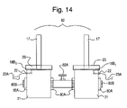
- FIG. 14 shows an alternate multiple launch system 82 in accordance with the sixth embodiment of the present invention whereas, two or more mixing containers 21 can be joined together with a connecting shut-off valve 82 A into reciprocal bosses 80 A to form a gang or chain of multiple launch tubes 17 and mixing containers 21 . Additionally all launch tubes 17 include an integral conductive end flange 17 B 1 and all mixing containers include an electrode 22 .
- shut-off valve 82 A when shut-off valve 82 A is in the open position the adjoining model rockets can be launched simultaneously. When the shut-off valve 82 A is in the closed position the adjoining rockets can be ignited independently.
- the shut-off valve 82 A allows the user to choose various combinations of the ignition sequence and method to launch model rockets.
- alternate multiple launch system 82 can be adapted and designed to launch multiple model rockets simultaneously or individually from two or more mixing containers with any of the model rocket and launch system embodiments in accordance with the present invention.
Landscapes
- Toys (AREA)
Abstract
Description
Claims (20)
Priority Applications (1)
| Application Number | Priority Date | Filing Date | Title |
|---|---|---|---|
| US11/391,701 US7537508B1 (en) | 2005-03-29 | 2006-03-29 | Carbide model rocketry system |
Applications Claiming Priority (2)
| Application Number | Priority Date | Filing Date | Title |
|---|---|---|---|
| US66587705P | 2005-03-29 | 2005-03-29 | |
| US11/391,701 US7537508B1 (en) | 2005-03-29 | 2006-03-29 | Carbide model rocketry system |
Publications (1)
| Publication Number | Publication Date |
|---|---|
| US7537508B1 true US7537508B1 (en) | 2009-05-26 |
Family
ID=40652069
Family Applications (1)
| Application Number | Title | Priority Date | Filing Date |
|---|---|---|---|
| US11/391,701 Expired - Fee Related US7537508B1 (en) | 2005-03-29 | 2006-03-29 | Carbide model rocketry system |
Country Status (1)
| Country | Link |
|---|---|
| US (1) | US7537508B1 (en) |
Cited By (3)
| Publication number | Priority date | Publication date | Assignee | Title |
|---|---|---|---|---|
| US10675550B2 (en) * | 2018-05-28 | 2020-06-09 | Idea Vault Holdings Inc. | Methods and apparatus for launching projectiles |
| US20210205723A1 (en) * | 2018-06-06 | 2021-07-08 | Scholz & Gallus Entwicklungsgesellschaft mbH | Holding and take-off device for hydropneumatically driven aircraft, in particular model rockets |
| CN116486673A (en) * | 2023-06-21 | 2023-07-25 | 中国人民解放军国防科技大学 | A two-stage model rocket integrated with a solid rocket and a water rocket |
Citations (2)
| Publication number | Priority date | Publication date | Assignee | Title |
|---|---|---|---|---|
| US20020121214A1 (en) * | 2000-07-05 | 2002-09-05 | Francis Ledys | Avanlanche triggering projectile |
| US6679155B1 (en) * | 2002-10-24 | 2004-01-20 | Johnson Research & Development Co., Inc. | Projectile launcher |
-
2006
- 2006-03-29 US US11/391,701 patent/US7537508B1/en not_active Expired - Fee Related
Patent Citations (2)
| Publication number | Priority date | Publication date | Assignee | Title |
|---|---|---|---|---|
| US20020121214A1 (en) * | 2000-07-05 | 2002-09-05 | Francis Ledys | Avanlanche triggering projectile |
| US6679155B1 (en) * | 2002-10-24 | 2004-01-20 | Johnson Research & Development Co., Inc. | Projectile launcher |
Cited By (5)
| Publication number | Priority date | Publication date | Assignee | Title |
|---|---|---|---|---|
| US10675550B2 (en) * | 2018-05-28 | 2020-06-09 | Idea Vault Holdings Inc. | Methods and apparatus for launching projectiles |
| US20210205723A1 (en) * | 2018-06-06 | 2021-07-08 | Scholz & Gallus Entwicklungsgesellschaft mbH | Holding and take-off device for hydropneumatically driven aircraft, in particular model rockets |
| US11484809B2 (en) * | 2018-06-06 | 2022-11-01 | Scholz & Gallus Gmbh | Holding and take-off device for hydropneumatically driven aircraft, in particular model rockets |
| CN116486673A (en) * | 2023-06-21 | 2023-07-25 | 中国人民解放军国防科技大学 | A two-stage model rocket integrated with a solid rocket and a water rocket |
| CN116486673B (en) * | 2023-06-21 | 2023-08-29 | 中国人民解放军国防科技大学 | Solid rocket and water rocket integrated two-stage model rocket |
Similar Documents
| Publication | Publication Date | Title |
|---|---|---|
| US12368308B2 (en) | Charger assembly and charging system for an electronic vaping device | |
| US11779050B2 (en) | E-vapor device including puncture device and sealed packet of pre-vapor formulation | |
| US10299516B2 (en) | Electronic article | |
| US6679155B1 (en) | Projectile launcher | |
| US9629394B2 (en) | Portable vaporizer with central pin heater having heat diffuser-mixer blades | |
| US4133301A (en) | Gas heating method and apparatus | |
| US20140216484A1 (en) | Electronic cigarette | |
| US20150034102A1 (en) | Solar Powered Electric Cigarette | |
| US8593104B2 (en) | Power source for starting engines of vehicles and the like | |
| US10912900B2 (en) | System and method for vaporizing substances for inhalation | |
| US7537508B1 (en) | Carbide model rocketry system | |
| FR2630822A1 (en) | DEVICE FOR LAUNCHING PROJECTILES | |
| MXPA06009956A (en) | Fuel vapor systems fo rinternal combustion engines. | |
| US7914281B2 (en) | Gas combustion apparatus and combustion gas setting device thereof | |
| US3406001A (en) | Battery powered gas fueled igniter device | |
| US2307007A (en) | Ignition apparatus | |
| FR2627848A1 (en) | WIND PROTECTED GAS LIGHTER | |
| JPS6026251Y2 (en) | Oil combustor vaporizer | |
| US2587713A (en) | Fuel-mixture vaporizer for gas engines | |
| FR2975168A1 (en) | HOT AIR GENERATING APPARATUS WITH IMPROVED IGNITION. | |
| US3336505A (en) | Automatically ignited lighter | |
| EP0561020B1 (en) | Cigarette gas lighter | |
| SU820845A1 (en) | Device for pulsed expelling of liquid | |
| KR100575269B1 (en) | Self-heating portable cup | |
| JP3138957U (en) | Internal combustion mechanism |
Legal Events
| Date | Code | Title | Description |
|---|---|---|---|
| AS | Assignment |
Owner name: PICONE PRODUCTS, INC., NEW YORK Free format text: ASSIGNMENT OF ASSIGNORS INTEREST;ASSIGNORS:PICONE, JOHN;PICONE, NICHOLAS;REEL/FRAME:017688/0877 Effective date: 20060425 |
|
| STCF | Information on status: patent grant |
Free format text: PATENTED CASE |
|
| FPAY | Fee payment |
Year of fee payment: 4 |
|
| REMI | Maintenance fee reminder mailed | ||
| FPAY | Fee payment |
Year of fee payment: 8 |
|
| SULP | Surcharge for late payment |
Year of fee payment: 7 |
|
| FEPP | Fee payment procedure |
Free format text: MAINTENANCE FEE REMINDER MAILED (ORIGINAL EVENT CODE: REM.); ENTITY STATUS OF PATENT OWNER: SMALL ENTITY |
|
| LAPS | Lapse for failure to pay maintenance fees |
Free format text: PATENT EXPIRED FOR FAILURE TO PAY MAINTENANCE FEES (ORIGINAL EVENT CODE: EXP.); ENTITY STATUS OF PATENT OWNER: SMALL ENTITY |
|
| STCH | Information on status: patent discontinuation |
Free format text: PATENT EXPIRED DUE TO NONPAYMENT OF MAINTENANCE FEES UNDER 37 CFR 1.362 |
|
| FP | Lapsed due to failure to pay maintenance fee |
Effective date: 20210526 |