US7530143B2 - Hinge mechanism for a foldable electronic device - Google Patents
Hinge mechanism for a foldable electronic device Download PDFInfo
- Publication number
- US7530143B2 US7530143B2 US11/303,491 US30349105A US7530143B2 US 7530143 B2 US7530143 B2 US 7530143B2 US 30349105 A US30349105 A US 30349105A US 7530143 B2 US7530143 B2 US 7530143B2
- Authority
- US
- United States
- Prior art keywords
- housing
- torsion spring
- main shaft
- hinge mechanism
- shaft
- Prior art date
- Legal status (The legal status is an assumption and is not a legal conclusion. Google has not performed a legal analysis and makes no representation as to the accuracy of the status listed.)
- Expired - Fee Related, expires
Links
Images


Classifications
-
- H—ELECTRICITY
- H04—ELECTRIC COMMUNICATION TECHNIQUE
- H04M—TELEPHONIC COMMUNICATION
- H04M1/00—Substation equipment, e.g. for use by subscribers
- H04M1/02—Constructional features of telephone sets
- H04M1/0202—Portable telephone sets, e.g. cordless phones, mobile phones or bar type handsets
- H04M1/0206—Portable telephones comprising a plurality of mechanically joined movable body parts, e.g. hinged housings
- H04M1/0208—Portable telephones comprising a plurality of mechanically joined movable body parts, e.g. hinged housings characterized by the relative motions of the body parts
- H04M1/0214—Foldable telephones, i.e. with body parts pivoting to an open position around an axis parallel to the plane they define in closed position
- H04M1/0216—Foldable in one direction, i.e. using a one degree of freedom hinge
-
- E—FIXED CONSTRUCTIONS
- E05—LOCKS; KEYS; WINDOW OR DOOR FITTINGS; SAFES
- E05F—DEVICES FOR MOVING WINGS INTO OPEN OR CLOSED POSITION; CHECKS FOR WINGS; WING FITTINGS NOT OTHERWISE PROVIDED FOR, CONCERNED WITH THE FUNCTIONING OF THE WING
- E05F1/00—Closers or openers for wings, not otherwise provided for in this subclass
- E05F1/08—Closers or openers for wings, not otherwise provided for in this subclass spring-actuated, e.g. for horizontally sliding wings
- E05F1/10—Closers or openers for wings, not otherwise provided for in this subclass spring-actuated, e.g. for horizontally sliding wings for swinging wings, e.g. counterbalance
- E05F1/12—Mechanisms in the shape of hinges or pivots, operated by springs
- E05F1/1207—Mechanisms in the shape of hinges or pivots, operated by springs with a coil spring parallel with the pivot axis
- E05F1/1215—Mechanisms in the shape of hinges or pivots, operated by springs with a coil spring parallel with the pivot axis with a canted-coil torsion spring
-
- E—FIXED CONSTRUCTIONS
- E05—LOCKS; KEYS; WINDOW OR DOOR FITTINGS; SAFES
- E05F—DEVICES FOR MOVING WINGS INTO OPEN OR CLOSED POSITION; CHECKS FOR WINGS; WING FITTINGS NOT OTHERWISE PROVIDED FOR, CONCERNED WITH THE FUNCTIONING OF THE WING
- E05F1/00—Closers or openers for wings, not otherwise provided for in this subclass
- E05F1/08—Closers or openers for wings, not otherwise provided for in this subclass spring-actuated, e.g. for horizontally sliding wings
- E05F1/10—Closers or openers for wings, not otherwise provided for in this subclass spring-actuated, e.g. for horizontally sliding wings for swinging wings, e.g. counterbalance
- E05F1/12—Mechanisms in the shape of hinges or pivots, operated by springs
- E05F1/1292—Mechanisms in the shape of hinges or pivots, operated by springs with a gas spring
-
- E—FIXED CONSTRUCTIONS
- E05—LOCKS; KEYS; WINDOW OR DOOR FITTINGS; SAFES
- E05Y—INDEXING SCHEME ASSOCIATED WITH SUBCLASSES E05D AND E05F, RELATING TO CONSTRUCTION ELEMENTS, ELECTRIC CONTROL, POWER SUPPLY, POWER SIGNAL OR TRANSMISSION, USER INTERFACES, MOUNTING OR COUPLING, DETAILS, ACCESSORIES, AUXILIARY OPERATIONS NOT OTHERWISE PROVIDED FOR, APPLICATION THEREOF
- E05Y2999/00—Subject-matter not otherwise provided for in this subclass
Definitions
- the present invention generally relates to hinge mechanisms and, more particularly, to a hinge mechanism for hinging together housings of a foldable electronic device, such as a mobile phone or a PDA (Personal Digital Assistant).
- a foldable electronic device such as a mobile phone or a PDA (Personal Digital Assistant).
- a typical hinge mechanism for foldable mobile phones and other portable electronic devices incorporate a torsion spring to achieve the rotation between the main housing and the cover in order to help the device to selectably remain closed or open.
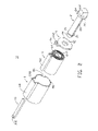
- the hinge mechanism includes a sleeve 91 , a torsion spring 92 , and a main shaft 93 .
- the sleeve 91 is substantially a hollow cylinder, with an open end and an opposite closed end. Disposed proximate the opposite closed end is an end portion 912 for latching with a cover section (not shown) of a foldable mobile phone (also not illustrated). Additionally, near the opposite closed end but opposing the end portion 912 is defined a blind receiving hole 914 , with inner threads.
- a given finger 922 , 924 extends from the two ends of the torsion spring 92 , respectively.
- the main shaft 93 has a fixing portion 932 at one end thereof and a flange 934 at another opposite end.
- the fixing portion 932 has outer threads defined thereon.
- the torsion spring 92 is received in the sleeve 91 .
- the finger 924 is engaged with a body section (not shown) of the foldable mobile phone.
- the main shaft 93 is inserted into the sleeve 91 , and the fixing portion 932 is mounted into the blind receiving hole 914 of the sleeve 91 .
- the hinge mechanism thus is completely assembled.
- the duly assembled hinge mechanism is then received in the body section of the foldable mobile phone.
- the end portion 912 is engaged with a cover section (not shown), and the finger 924 is operative with the body section.
- the torsion spring 92 has a predetermined torsion.
- the cover section is mated through a locking mechanism (not shown), such as a magnet. The magnetic force can make the cover section close to the body section.
- the locking mechanism When in use, the locking mechanism is released, and the cover section is opened via the torsion of the spring 92 .
- the structure of the hinge mechanism is simple, and the operation is convenient.
- the torsion force of the whole hinge mechanism suffers from the end portion 912 of the sleeve 91 .
- the end portion 912 is small and thus requires a higher strength.
- the impact force burdens the body section and the cover section.
- the body section and the cover section as such, are easily worn, thereby shortening the working lifetime of the foldable mobile phone.
- the body section must be specially constructed in order to permit engagement thereof with the finger 924 . Therefore, the hinge mechanism has a poor exchangeability (i.e., not readily interchangeable), which could increase the cost of the mobile phones employing such a hinge mechanism.
- the present hinge mechanism includes a main shaft, a torsion spring, and a housing.
- the main shaft has a first shaft end and an opposite second shaft end.
- the main shaft further includes a stopping mechanism, provided at the first shaft end.
- the torsion spring surrounds the main shaft.
- the torsion spring has two ends and a substantially hollow interior.
- the housing is cylinder-shaped and hollow, having a first housing end and a second housing end. The first housing end thereof is open and sized to receive the torsion spring therein.
- the second housing end has a shaft-receiving opening sized and configured to receive the main shaft therein.
- the torsion spring is inserted into the housing.
- the main shaft is inserted into the torsion spring and received in the second opening of the housing.
- the stopping mechanism prevents the main shaft from becoming disassembled from the housing.
- An electronic device includes a main housing, a cover, and the present hinge mechanism.
- the hinge mechanism is used to rotatably hinge the main housing and the cover.
- the housing and the main shaft of the present hinge mechanism respectively engage with the main housing and the cover.
- the hinge mechanism has a nice exchangeability and could potentially be employed in any of a variety of situations in which it desired that a hinge be configured for selectably maintaining one of an open and closed position.
- FIG. 1 is an exploded, isometric view of a conventional hinge mechanism
- FIG. 2 is an exploded, isometric view of the present hinge mechanism, in accordance with a preferred embodiment thereof;
- FIG. 3 is similar to FIG. 2 , but viewed from an opposite direction;
- FIG. 4 is an assembled, isometric view of the hinge mechanism of FIG. 2 ;
- FIG. 5 is an isometric view of an electronic device employing the hinge mechanism of FIG. 4 .
- a hinge mechanism 12 includes a main shaft 2 , a washer 4 , a torsion spring 6 , a housing 8 and a pin 10 .
- FIG. 5 shows the hinge mechanism 12 in use within a mobile phone 100 having a main housing 14 and a cover 16 , in accordance with a preferred embodiment.
- the hinge mechanism 12 is shown and detailed as follows for the purposes of providing a simple description of the preferred embodiment thereof, and the embodiments thereof are not to be construed as being limited to the following description.
- the main shaft 2 is approximately column-shaped and has a first shaft end 20 and an opposite second shaft end 21 .
- a fixing portion 22 and a stopping portion 24 are formed at the first shaft end 20
- a flange 26 is formed at the second shaft end 21 of the main shaft 2 .
- the flange 26 is beneficially in the shape of a frustum of a cone, easing its insertion through a hole 82 within the housing 8 but making it difficult to remove thereafter.
- a slot 28 is defined in the main shaft 2 and runs along an axis thereof. The slot 28 runs from a side of the stopping portion 24 facing the flange 26 and through the flange 26 .
- the fixing portion 22 is used to engage with the main housing 14 of the mobile phone 100 .
- the stopping portion 24 and the flange 26 are each configured for stopping/preventing the main shaft 2 from becoming disassembled from the hinge mechanism 12 or from at least sliding out of place relative to remainder of the assembly.
- the washer 4 is approximately ring-shaped.
- a central hole 42 is defined in the washer 4 along a central axis thereof.
- the washer 4 forms two protrusions 44 and a catch piece 46 at the edge/outer periphery thereof.
- the protrusions 44 and the catch piece 46 are arranged symmetrically along the outer periphery of the washer 4 .
- a rectangular hole 462 is defined in the catch piece 46 .
- the torsion spring 6 is formed of a piece of metal sheet.
- the metal sheet coils into several layers of approximate cylinders (i.e., multiple essentially cylindrical coils) to form the main portion of the torsion spring 6 .
- An end portion of the outside layer of the torsion spring 6 is bent into a hollow, approximately cuboid-shaped (i.e., a rectangular-parallelepiped shape) mounting portion 62 .
- An end of the inside layer of the torsion spring 6 coils into a holding portion 64 , which is substantially hollow and specifically configured for receiving the main shaft 2 therein.
- the cross-section of the holding portion 64 is “S” shaped.
- the central section of the holding portion 64 is a flat holding piece 642 , which extends at least part of the length of the torsion spring 6 (more advantageously, substantially, if not all, the length thereof, to promote better engagement with the slot 28 of the main shaft 2 ).
- the holding piece 642 engages the slot 28 of the main shaft 2 , upon insertion of the main shaft 2 into the holding portion 64 of the torsion spring 6 .
- the torsion spring 6 is received in the housing 8 .
- the housing 8 is approximately in the shape of a hollow cylinder.
- the housing 8 has an open end 80 and a second end, which has a hole 82 therein.
- a hollow projection 84 is formed on the sidewall of the housing 8 along a line parallel to an axis of the housing 8 .
- a gap 840 is defined at the open end 80 of the projection 84 .
- the housing 8 with its projection 84 , is appropriately configured for receiving the torsion spring 6 , with its mounting portion 62 , therein.
- An inserting hole 842 is defined at the opposite end of the projection 84 .
- a figure of the open end 80 is matingly the same as the section figure of the washer 4 .
- Two grooves 86 are defined at the open end 80 .
- Positions of the gap 840 and the grooves 86 correspond to the positions of the catch piece 46 and the protrusions 44 of the washer 4 , so that the washer 4 can be received in the open end 80 of the housing 8 .
- the projection 84 of the housing 8 is used to engage with the cover 16 of the mobile phone 100 .
- the pin 10 is cuboid-shaped and has a hook 102 at one end thereof.
- the pin 10 is contained in the projection 84 of the housing 8 and, more specifically, is slidingly inserted into the mounting portion 62 of the torsion spring 6 .
- the hook 102 of the pin 10 thus engages with the one end of the projection 84 where the inserting hole 842 is located.
- the torsion spring 6 When assembling the hinge mechanism 12 , firstly, the torsion spring 6 is placed into the housing 8 , and the mounting portion 62 is directed into the projection 84 . Next, the washer 4 is mounted at the open end 80 of the housing 8 . The catch piece 46 and the protrusions 44 of the washer 4 are respectively accepted in the gap 840 and the grooves 86 of the housing 8 . Then, the main shaft 2 is sequentially run through the central hole 42 of the washer 4 , the holding portion 64 of the torsion spring 6 , and the hole 82 of the housing 8 , with the holding piece 642 of the torsion spring 6 , in turn, running through the slot 28 of the main shaft 2 .
- the flange 26 deforms and is locked at the opposite end of the open end 80 of the housing 8 because a maximum diameter of the flange 26 is larger than that of the hole 82 .
- the stopping portion 24 is stopped by the washer 4 as a diameter of the stopping portion 24 is larger than that of the central hole 42 of the washer 4 , thereby helping to properly position the main shaft 2 .
- the pin 10 is sequentially inserted into the inserting hole 842 of the housing 8 , the mounting portion 62 of the torsion spring 6 , and the rectangular hole 462 of the washer 4 .
- the pin 10 is stopped at the side of the inserting hole 842 by the hook 102 .
- the hook 102 is fixed on the housing 8 by, e.g., gluing, plastering, soldering, or melting/welding.
- the hinge mechanism 12 is thereby assembled, as best shown in FIG. 4 .
- the mounting portion 62 of the torsion spring 6 is fixed to the housing 8
- the holding portion 64 of the torsion spring 6 is fixed to the main shaft 2 .
- the hinge mechanism 12 is used in the exemplary mobile phone 100 having the main housing 14 and the cover 16 .
- the assembled hinge mechanism 12 is assembled to connecting portions (not shown) of the main housing 14 and the cover 16 .
- the housing 8 engages with the cover 16 by the projection 84 .
- the housing 8 can rotate together with the cover 16 relative to the main housing 14 .
- the main shaft 2 engages with the main housing 14 by the fixing portion 22 .
- the mounting portion 62 of the torsion spring 6 is fixed relative to the cover 16
- the holding portion 64 of the torsion spring 6 is fixed relative to the main housing 14 .
- the torsion spring 6 When the cover 16 is closed, the torsion spring 6 is in a twisted state, and the cover 16 is fixed to the main housing 14 by a fixing structure or a magnetic mechanism.
- the hinge mechanism 12 is in an unsteady state, and the cover 16 is apt to open relative to the main housing 15 .
- the fixing structure or magnetic mechanism is manually released.
- the holding portion 64 of the torsion spring 6 is released and rotates due to the resilient force of the torsion spring 6 . Therefore, the cover 16 rotates together with the housing 8 , since the housing 8 is fixed relative to the mounting portion 62 . As such, the cover 16 is opened.
- the torsion spring 6 is completely released, and the cover 16 stops rotating.
- the cover 16 can also be opened to a prearranged angle, limited by a structural limitation of the main housing 14 and the cover 16 .
- the cover 16 is rotated manually and then fixed to the main housing 14 by the fixing structure or the magnetic mechanism.
- the pin 10 can be omitted, and the holding portion 64 of the torsion spring 6 could fixed to the housing 8 directly by pasting/gluing, soldering, or melting, for example.
- the slot 28 of the main shaft 2 can also be omitted, so long as the holding portion 64 is eliminated and the main shaft 2 is then otherwise attached to the torsion spring 6 (e.g., adhesively or metallurgically).
- the washer 4 also can be omitted.
- the torsion spring 6 can be of another form, such as a column helical spring, as long as it can attach to and/or engage with the housing 8 .
- the flange 26 of the main shaft 2 can be replaced with another stopping mechanism, such as a ring or a nut, arranged at the second shaft end 21 of the main shaft 2 , in order to stop the main shaft 2 from becoming disassembled from the housing 8 .
- another stopping mechanism such as a ring or a nut, arranged at the second shaft end 21 of the main shaft 2 , in order to stop the main shaft 2 from becoming disassembled from the housing 8 .
- the hinge mechanism 12 could have potential applications beyond foldable electronic devices (e.g., cabinet doors), and such uses are considered to be within the scope of use of this hinge assembly 12 .
Landscapes
- Engineering & Computer Science (AREA)
- Signal Processing (AREA)
- Telephone Set Structure (AREA)
Abstract
Description
Claims (14)
Applications Claiming Priority (2)
| Application Number | Priority Date | Filing Date | Title |
|---|---|---|---|
| CN200410091872.XA CN1798490A (en) | 2004-12-23 | 2004-12-23 | Hinge structure |
| CN200410091872.X | 2004-12-23 |
Publications (2)
| Publication Number | Publication Date |
|---|---|
| US20060137142A1 US20060137142A1 (en) | 2006-06-29 |
| US7530143B2 true US7530143B2 (en) | 2009-05-12 |
Family
ID=36609688
Family Applications (1)
| Application Number | Title | Priority Date | Filing Date |
|---|---|---|---|
| US11/303,491 Expired - Fee Related US7530143B2 (en) | 2004-12-23 | 2005-12-16 | Hinge mechanism for a foldable electronic device |
Country Status (2)
| Country | Link |
|---|---|
| US (1) | US7530143B2 (en) |
| CN (1) | CN1798490A (en) |
Cited By (3)
| Publication number | Priority date | Publication date | Assignee | Title |
|---|---|---|---|---|
| US20100011536A1 (en) * | 2008-07-21 | 2010-01-21 | Chi Mei Communication Systems, Inc. | Hinge mechanism for foldable electronic device |
| US20100107368A1 (en) * | 2008-11-05 | 2010-05-06 | Honh Fu Jin Precision Industry (Shenzhen) Co., Ltd | Hinge assembly |
| US8307503B1 (en) * | 2009-10-02 | 2012-11-13 | George Burger | Slow closing hinge apparatus |
Families Citing this family (9)
| Publication number | Priority date | Publication date | Assignee | Title |
|---|---|---|---|---|
| WO2005010379A1 (en) * | 2003-07-28 | 2005-02-03 | Fujitsu Limited | Mobile radio communication equipment |
| WO2005010378A1 (en) * | 2003-07-28 | 2005-02-03 | Fujitsu Limited | Mobile radio communication equipment |
| US7500288B2 (en) * | 2006-09-26 | 2009-03-10 | Shin Zu Shing Co., Ltd. | Hinge |
| CN101489367B (en) * | 2008-01-14 | 2011-08-31 | 深圳富泰宏精密工业有限公司 | Hinge sleeve and portable electronic apparatus applying the hinge sleeve |
| CN101605438B (en) * | 2008-06-13 | 2011-09-21 | 深圳富泰宏精密工业有限公司 | Cap screwing mechanism |
| CN101725621B (en) * | 2008-10-14 | 2012-09-19 | 鸿富锦精密工业(深圳)有限公司 | hinge structure |
| US8402609B2 (en) * | 2009-12-31 | 2013-03-26 | Shin Zu Shing Co., Ltd. | Self-lock hinge |
| CN103510774B (en) * | 2013-09-25 | 2016-02-10 | 北京中家智铭设计有限公司 | A kind of hinge |
| CN115022768B (en) * | 2022-08-04 | 2023-06-16 | 龙旗电子(惠州)有限公司 | Earphone charging box connecting device and earphone charging box |
Citations (8)
| Publication number | Priority date | Publication date | Assignee | Title |
|---|---|---|---|---|
| US2713820A (en) * | 1950-07-11 | 1955-07-26 | Horii Shinjiro | Flat duplicator |
| US3351976A (en) * | 1965-04-28 | 1967-11-14 | Gen Motors Corp | Vehicle body door hinge and hold-open |
| US6065187A (en) * | 1998-05-14 | 2000-05-23 | Motorola, Inc. | Hinge assembly |
| US6070298A (en) | 1996-10-28 | 2000-06-06 | Ratoh Electrical Machinery Co., Ltd. | Composite torque hinges |
| US6493542B1 (en) | 1999-03-23 | 2002-12-10 | Telefonaktiebolaget Lm Ericsson (Publ) | Arrangement at a mobile telephone |
| US20040020012A1 (en) * | 2002-08-02 | 2004-02-05 | Gupte Sheel A. | Self-contained hinge for flip-style device |
| US20060085947A1 (en) * | 2004-10-22 | 2006-04-27 | Fih Co.,Ltd | Hinge and a mobile phone with the hinge |
| US20060230578A1 (en) * | 2005-04-13 | 2006-10-19 | Renke David T | Gooseneck hinge assembly for vehicles |
-
2004
- 2004-12-23 CN CN200410091872.XA patent/CN1798490A/en active Pending
-
2005
- 2005-12-16 US US11/303,491 patent/US7530143B2/en not_active Expired - Fee Related
Patent Citations (9)
| Publication number | Priority date | Publication date | Assignee | Title |
|---|---|---|---|---|
| US2713820A (en) * | 1950-07-11 | 1955-07-26 | Horii Shinjiro | Flat duplicator |
| US3351976A (en) * | 1965-04-28 | 1967-11-14 | Gen Motors Corp | Vehicle body door hinge and hold-open |
| US6070298A (en) | 1996-10-28 | 2000-06-06 | Ratoh Electrical Machinery Co., Ltd. | Composite torque hinges |
| US6065187A (en) * | 1998-05-14 | 2000-05-23 | Motorola, Inc. | Hinge assembly |
| US6493542B1 (en) | 1999-03-23 | 2002-12-10 | Telefonaktiebolaget Lm Ericsson (Publ) | Arrangement at a mobile telephone |
| US20040020012A1 (en) * | 2002-08-02 | 2004-02-05 | Gupte Sheel A. | Self-contained hinge for flip-style device |
| US20050257343A1 (en) * | 2002-08-02 | 2005-11-24 | Amphenol-T&M Antennas | Self-contained hinge for flip-style device |
| US20060085947A1 (en) * | 2004-10-22 | 2006-04-27 | Fih Co.,Ltd | Hinge and a mobile phone with the hinge |
| US20060230578A1 (en) * | 2005-04-13 | 2006-10-19 | Renke David T | Gooseneck hinge assembly for vehicles |
Cited By (4)
| Publication number | Priority date | Publication date | Assignee | Title |
|---|---|---|---|---|
| US20100011536A1 (en) * | 2008-07-21 | 2010-01-21 | Chi Mei Communication Systems, Inc. | Hinge mechanism for foldable electronic device |
| US20100107368A1 (en) * | 2008-11-05 | 2010-05-06 | Honh Fu Jin Precision Industry (Shenzhen) Co., Ltd | Hinge assembly |
| US8087128B2 (en) * | 2008-11-05 | 2012-01-03 | Hong Fu Jin Precision Industry (Shenzhen) Co., Ltd. | Hinge assembly |
| US8307503B1 (en) * | 2009-10-02 | 2012-11-13 | George Burger | Slow closing hinge apparatus |
Also Published As
| Publication number | Publication date |
|---|---|
| US20060137142A1 (en) | 2006-06-29 |
| CN1798490A (en) | 2006-07-05 |
Similar Documents
| Publication | Publication Date | Title |
|---|---|---|
| US7530143B2 (en) | Hinge mechanism for a foldable electronic device | |
| US8240007B2 (en) | Hinge assembly for foldable electronic device | |
| US8099833B2 (en) | Washer for hinge assembly | |
| US7913356B2 (en) | Hinge assembly for foldable electronic devices | |
| US20100162526A1 (en) | Hinge assembly for foldable electronic device | |
| US8370994B2 (en) | Automatically opening hinge assembly for portable electronic devices | |
| US20060242796A1 (en) | Automatical opening hinge assembly for portable electronic devices | |
| KR20030071284A (en) | Hinge device and portable terminal therewith | |
| US20100180401A1 (en) | Hinge housing for hinge assembly | |
| US7568263B2 (en) | Hinge apparatus and watch type portable terminal having the same | |
| US7627930B2 (en) | Automatically opening hinge assembly for portable electronic devices | |
| US7353568B2 (en) | Hinge assembly for foldable electronic device | |
| US7647674B2 (en) | Automatically opening hinge assembly for portable electronic devices | |
| US20060112516A1 (en) | Hinge assembly for portable electronic devices | |
| US20070039135A1 (en) | Hinge assembly for foldable electronic device | |
| US8141205B2 (en) | Hinge mechanism and portable electronic device using the same | |
| US20060070211A1 (en) | Hinge mechanism for foldable electronic device | |
| US7578030B2 (en) | Hinge mechanism for foldable electronic device | |
| US7814619B2 (en) | Opening and closing device | |
| US7444715B2 (en) | Hinge mechanism for foldable electronic device | |
| US7814620B2 (en) | Hinge | |
| US7747005B2 (en) | Opening and closing mechanism, and electronic device | |
| US7334294B2 (en) | Hinge and foldable electronic device using the hinge | |
| US20060154701A1 (en) | Hinge assembly for foldable electronic device | |
| US8078236B2 (en) | Rotary cover mechanism for portable electronic devices |
Legal Events
| Date | Code | Title | Description |
|---|---|---|---|
| AS | Assignment |
Owner name: FIH CO., LTD., TAIWAN Free format text: ASSIGNMENT OF ASSIGNORS INTEREST;ASSIGNORS:QIN, SHUI-YUAN;LUO, XING-HUANG;TU, HSIAO-HUA;AND OTHERS;REEL/FRAME:017382/0819 Effective date: 20051130 |
|
| AS | Assignment |
Owner name: SUTECH TRADING LIMITED, VIRGIN ISLANDS, BRITISH Free format text: ASSIGNMENT OF ASSIGNORS INTEREST;ASSIGNOR:FIH CO., LTD;REEL/FRAME:018657/0836 Effective date: 20061113 Owner name: SHENZHEN FUTAIHONG PRECISION INDUSTRIAL CO., LTD, Free format text: ASSIGNMENT OF ASSIGNORS INTEREST;ASSIGNOR:FIH CO., LTD;REEL/FRAME:018657/0836 Effective date: 20061113 Owner name: SUTECH TRADING LIMITED, VIRGIN ISLANDS, BRITISH Free format text: ASSIGNMENT OF ASSIGNORS INTEREST;ASSIGNOR:FIH CO., LTD;REEL/FRAME:018663/0612 Effective date: 20061113 Owner name: SHENZHEN FUTAIHONG PRECISION INDUSTRIAL CO., LTD, Free format text: ASSIGNMENT OF ASSIGNORS INTEREST;ASSIGNOR:FIH CO., LTD;REEL/FRAME:018663/0612 Effective date: 20061113 |
|
| AS | Assignment |
Owner name: FIH (HONG KONG) LIMITED, HONG KONG Free format text: ASSIGNMENT OF ASSIGNORS INTEREST;ASSIGNOR:SUTECH TRADING LIMITED;REEL/FRAME:022618/0378 Effective date: 20090428 |
|
| REMI | Maintenance fee reminder mailed | ||
| LAPS | Lapse for failure to pay maintenance fees | ||
| STCH | Information on status: patent discontinuation |
Free format text: PATENT EXPIRED DUE TO NONPAYMENT OF MAINTENANCE FEES UNDER 37 CFR 1.362 |
|
| STCH | Information on status: patent discontinuation |
Free format text: PATENT EXPIRED DUE TO NONPAYMENT OF MAINTENANCE FEES UNDER 37 CFR 1.362 |
|
| FP | Lapsed due to failure to pay maintenance fee |
Effective date: 20130512 |