US751663A - Caster-horn - Google Patents
Caster-horn Download PDFInfo
- Publication number
- US751663A US751663A US751663DA US751663A US 751663 A US751663 A US 751663A US 751663D A US751663D A US 751663DA US 751663 A US751663 A US 751663A
- Authority
- US
- United States
- Prior art keywords
- horn
- blank
- metal
- plate
- caster
- Prior art date
- Legal status (The legal status is an assumption and is not a legal conclusion. Google has not performed a legal analysis and makes no representation as to the accuracy of the status listed.)
- Expired - Lifetime
Links
Images
Classifications
-
- B—PERFORMING OPERATIONS; TRANSPORTING
- B60—VEHICLES IN GENERAL
- B60B—VEHICLE WHEELS; CASTORS; AXLES FOR WHEELS OR CASTORS; INCREASING WHEEL ADHESION
- B60B33/00—Castors in general; Anti-clogging castors
- B60B33/0002—Castors in general; Anti-clogging castors assembling to the object, e.g. furniture
Definitions
- This invention relates to a novel casterhorn.
- the object of the invention is to produce by a simple and economical method a sheet-metal caster-horn stilfened uniformly throughout the shanks and crown by a continuous Inarginal flange drawn up from the material of the horn-body as distinguished from a stiiI- ching-flange produced by bending up surplus metal provided by forming a blank of greater dimensions than the body of the horn to be made.
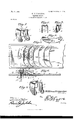
- Figure 1 is a perspective view of a caster-horn constructed in accordance with my invention.
- Fig. 2 is a sectional view thereof.
- Fig. 3 is a similar view, the section being taken on a line at right angles to the line of section of Fig. 2.
- Fig. 4 is a detail view of the blank as it is delivered from the press.
- Fig. 5 is a plan view of the bed or die plate with a stock sheet in position thereon.
- Fig. 6 is a sectional view on the line 66 of Fig. 5 and showing in part the perforating, pressing, and blanking devices capable of being utilized in the practice of the method; and
- Fig. 7 is a perspective view of a modified form of horn comprehended by my invention.
- my invention is directed to the 8 5 production of a horn requiring a blank the general contour of which will serve to minimize the waste of stock, the requisite stiffness of which will be secured by a flange extending continuously around the margin of the horn, 90 including both the shanks and the crown thereof, and the cost of manufacture of which will be minimized by drawing up the marginal flange from the body of the horn instead of producing said flange from surplus metal 95 resulting from the formation of a blank of abnormal size.
- the horn l comprises the crown-plate 2,
- the crown-plate is formed with a central opening 5 for the reception of a spindle, (not shown,) and from the margin of this opening extends at right angles to the crownplate an annular bearing flange or bushing 6, drawn from the plate.
- the caster-wheel (not shown) is designed to be received between the shanks 3 and 4, and the latter are therefore provided at their lower ends with alined openings 7 for the reception of the wheel-trun.
- the horn is constructed from comparatively thin sheet metal, and the requisite stiffness both of the crown-plate and shanks and of their connections is secured by a marginal flange, web, or bead 8, extending continuously around the entire margin of the horn and disposed at an angle to the body thereof.
- This liange 8 is not formed by merely bending up the outer edge of the blank, but is drawn up from the body of the blank, so that the ianged horn is produced in its entirety from a blank having no greater dimensions than the body portion of the horn. In other words, the production of my stiifening-flange is not accompanied by a corresponding consumption of the stock.
- the iange 8 extends downwardly from the crown-plate and inwardly from the shankS, as shown in Fig. 1, or upwardly from the plate and outwardly from the shanks, as shown in Fig. 7
- FIG. 5 and 6 of the drawings a portion of one form of mechanism which may be employed in the production of my improved horn.
- a suitable bed or die plate 9 is provided with an opening 5 and similar openings 7 L of somewhat smaller size.
- rIhe opening 5a is designed to accommodate a punch 5b, which moves upwardly through the bed 9 and is received within the lower end of a die 5C, located above the bed.
- the openings 7 a are disposed to accommodate the descending punches 7b.
- a sheet-metal stock plate 10 of the proper thickness and of a width slightly greater than the length of the blank to be produced is placed upon the bed 9 and is fed forward to a position over the openings 7L and 5, which correspond in their relative positions to the openings 5 and 7 of ahorn-blank.
- the plate being in position, the punches 7b descend to form the openings 7 in the plate and the punch ascends.
- the punch will draw up the annular fange 6, surrounding the opening or perforation 5, produced by the punch.
- the punches and die having been retracted the stock plate will be advanced to bring the perforated portion thereof opposite a depression 11, formed in the surface of the bed 9 and corresponding in size and form to the body of the horn to be produced.
- a depression formed in the surface of the bed 9 and corresponding in size and form to the body of the horn to be produced.
- the metal for the formation of the blank is dropped or depressed by a presser 12, corresponding in form with the contour of the depression, but of slightly-smaller size, in order to leave a narrow space between its side face and the side walls of the depression.
- a presser 12 corresponding in form with the contour of the depression, but of slightly-smaller size, in order to leave a narrow space between its side face and the side walls of the depression.
- the metal is forced down into the depression 11 it will be stretched or drawnnp to produce the marginal flange 8 by the drawing out of the metal.
- a punch 14 exactly corresponding with the opening 13 and arranged to be brought down, as indicated in Fig. 6, vto sever the completed horn-blank from the stock sheet.
- the blank shown in Fig. 4 will then be bent to produce the parallel shanks and the surmounting and connecting crown-plate 2, as shown in Fig. 1 of the drawings.
- the punches, the die, and the presser will all operate simultaneously, so that the three operations of perforating the metal, depressing' a perforated blank, and severing a depressed blank from the sheet will be effected simultaneously, to the end that each operation of the press will be accompanied bythe discharge of a completed blank.
- a Sheet-metal caster-horn constructed from a Single piece of metal and having a drawn Stitfeningflange extending continuously around itS entire margin.
- a Sheet-metal caster-horn having a drawn marginal iange of tapering Cross-Sectional contour Which extends continuously around the entire margin of the horn.
- a Sheet-metal caster-horn constructed from a Single piece of metal bent to i'orm a crown-plate and a pair of Shanks, and having a continuous drawn iange extending from the edgesl of the Shanks and crown-plate, and an annular flange or bushing extending from the crown-plate.
- a Sheet-metal caster-horn constructed from a Single piece of metal bent to form an apertured crown-plate and a pair of apertured Shanks, and having an annular bushing extending from the crown-plate, and a drawn flange of tapering cross-Sectional contour extending continuously around the edges of the Shanks and plate.
Description
v"No, 751,663. PATBNTBD PEB. 9, 1904,
W. LIVINGSTONE.
GASTER HORN.
APPLICATION FILED NGV. 29, 1902.
No MODEL.
514@ c 'n For.,
UNITED STATES x'atented February 9, 1904.
PATENT OEEICE.
vWILLIAM LIVINGSTONE, OF FLUSHING, NEV YORK, ASSIGNOR TO HIM- SELE, AND SAMUEL P. PORTER, OE BROOKLYN, NEW YORK.
CASTER-HORN.
SPECIFICATION forming part of Letters Patent 310.751,66?, dated February 9, 1904.
Application filed November 29, 1902. Serial No. 133,278. (No model.)
To all whom, it may concern:
Be it known that I, WILLIAM LIvINGstroNE, a citizen of the United States, residing at Flushing, in the county of Queens and State of New York, have invented a new and useful Improvement in Caster-Horns, of which the following is a specification.
This invention relates to a novel casterhorn.
The object of the invention is to produce by a simple and economical method a sheet-metal caster-horn stilfened uniformly throughout the shanks and crown by a continuous Inarginal flange drawn up from the material of the horn-body as distinguished from a stiiI- ching-flange produced by bending up surplus metal provided by forming a blank of greater dimensions than the body of the horn to be made.
Subordinate objects will appear as the nature of the invention is better understood.
In the accompanying drawings, Figure 1 is a perspective view of a caster-horn constructed in accordance with my invention. Fig. 2 is a sectional view thereof. Fig. 3 is a similar view, the section being taken on a line at right angles to the line of section of Fig. 2. Fig. 4 is a detail view of the blank as it is delivered from the press. Fig. 5 is a plan view of the bed or die plate with a stock sheet in position thereon. Fig. 6 is a sectional view on the line 66 of Fig. 5 and showing in part the perforating, pressing, and blanking devices capable of being utilized in the practice of the method; and Fig. 7 is a perspective view of a modified form of horn comprehended by my invention.
Like characters of reference are employed to designate corresponding parts throughout the several views.
In order that the relation of my invention to the art may be properly understood, it may be well by way of premise to call attention briefly to the distinguishing characteristics of the horn and the method of its production.
The ends the attainment of which is primarily sought by manufacturers ofthis class of devices are, Erst, great durability and stiness in order that the horn may sustain the weight of a heavy article of furniture for the support 5o of which it may be employed; second, simplicity of construction, whereby the employment of skilled labor may be dispensedv with, and, third, economy in the consumption of stock. With a view to the attainment of these 5 5 ends the old method of molding or casting and subsequently finishing the horn has given place to the more economical methods of producing caster-horns from sheet metal by the process of blanking and forming in the dies of a press. 6o Such of these horns as have come to my attention are ineflicient, iirst, because as ordinarily constructed they lack the requisite stiifness and durability; second, because of the necessity for the employment of heavy and eXpen- 65 sive stock; third, because the usual efforts to stifen the horn have been directed to the reinforcement of the crown by a separate piece of sheet metal or by enlarging the crown part of the .horn-blank to permit' it to be drawn 7o cup shaped downward, both of which not only involve a waste of stock, but also additional expense for labor in the manufacture of the horn, and, fourth, because when attempts have been made to secure additional 7 5 strength by fianging or corrugating the hornbody the requisite stiffness has not been attained without considerable waste of material resulting from the general design of blank required and from the necessity for producing a 8O blank of greater dimensions than the body of the horn in order to secure surplus metal for the stif'fening-anges. Having in' mind these various objections to the usual forms of sheetmetal horns, my invention is directed to the 8 5 production of a horn requiring a blank the general contour of which will serve to minimize the waste of stock, the requisite stiffness of which will be secured by a flange extending continuously around the margin of the horn, 90 including both the shanks and the crown thereof, and the cost of manufacture of which will be minimized by drawing up the marginal flange from the body of the horn instead of producing said flange from surplus metal 95 resulting from the formation of a blank of abnormal size.
The horn l comprises the crown-plate 2,
from the opposite ends of which depend the parallel shanks 3 and 4, integral with the crownplate and slightly curved longitudinally, as shown. The crown-plate is formed with a central opening 5 for the reception of a spindle, (not shown,) and from the margin of this opening extends at right angles to the crownplate an annular bearing flange or bushing 6, drawn from the plate. The caster-wheel (not shown) is designed to be received between the shanks 3 and 4, and the latter are therefore provided at their lower ends with alined openings 7 for the reception of the wheel-trun.
nions or for a rigid wheel-pin, as the case may be, it being understood that the particular mounting of the caster-wheel is immaterial, so far as my invention is concerned.
The horn is constructed from comparatively thin sheet metal, and the requisite stiffness both of the crown-plate and shanks and of their connections is secured by a marginal flange, web, or bead 8, extending continuously around the entire margin of the horn and disposed at an angle to the body thereof. This liange 8 is not formed by merely bending up the outer edge of the blank, but is drawn up from the body of the blank, so that the ianged horn is produced in its entirety from a blank having no greater dimensions than the body portion of the horn. In other words, the production of my stiifening-flange is not accompanied by a corresponding consumption of the stock. Obviously it is immaterial whether the iange 8 extends downwardly from the crown-plate and inwardly from the shankS, as shown in Fig. 1, or upwardly from the plate and outwardly from the shanks, as shown in Fig. 7
and it is likewise immaterial whether the bushing extends above or below the plate.
'1 Inorder that the essence of the invention may be clearly comprehended, I have illustratedin Figs. 5 and 6 of the drawings a portion of one form of mechanism which may be employed in the production of my improved horn. A suitable bed or die plate 9 is provided with an opening 5 and similar openings 7 L of somewhat smaller size. rIhe opening 5a is designed to accommodate a punch 5b, which moves upwardly through the bed 9 and is received within the lower end of a die 5C, located above the bed. The openings 7 a are disposed to accommodate the descending punches 7b. A sheet-metal stock plate 10 of the proper thickness and of a width slightly greater than the length of the blank to be produced is placed upon the bed 9 and is fed forward to a position over the openings 7L and 5, which correspond in their relative positions to the openings 5 and 7 of ahorn-blank. The plate being in position, the punches 7b descend to form the openings 7 in the plate and the punch ascends. As the die 5c is counterbored at its lower end, as indicated at 5d, the punch will draw up the annular fange 6, surrounding the opening or perforation 5, produced by the punch. The punches and die having been retracted the stock plate will be advanced to bring the perforated portion thereof opposite a depression 11, formed in the surface of the bed 9 and corresponding in size and form to the body of the horn to be produced. Into this depression the metal for the formation of the blank is dropped or depressed by a presser 12, corresponding in form with the contour of the depression, but of slightly-smaller size, in order to leave a narrow space between its side face and the side walls of the depression. As the metal is forced down into the depression 11 it will be stretched or drawnnp to produce the marginal flange 8 by the drawing out of the metal. This peculiarity of the method results in the production of a blank having a marginal flange without necessitating that waste of metal which would be necessary if the ange were turned up from surplus metal secured by cutting out a blank of greater dimensions than the body of the horn to be produced. Obviously this metal drawn up between the opposed side faces of the depression 11 and the presser 12 will not be of uniform thickness, but, on the contrary, will be drawn out to a tapering or wedge-shaped cross-sectional contour, as shown. The presser having been retracted, the stock plate is again moved forward to permit the depressed portion thereof to drop into an opening 13, formed in the bed 9 and corresponding exactly in contour and dimensions with the depression 11. Above the opening 13 is arranged a punch 14 exactly corresponding with the opening 13 and arranged to be brought down, as indicated in Fig. 6, vto sever the completed horn-blank from the stock sheet. The blank shown in Fig. 4 will then be bent to produce the parallel shanks and the surmounting and connecting crown-plate 2, as shown in Fig. 1 of the drawings. Of course in practice the punches, the die, and the presser will all operate simultaneously, so that the three operations of perforating the metal, depressing' a perforated blank, and severing a depressed blank from the sheet will be effected simultaneously, to the end that each operation of the press will be accompanied bythe discharge of a completed blank.
I wish it to be distinctly understood, how'- ever, that the invention is not limited to any particular mechanism for punching, pressing, or cutting the blank, since the construction of a caster-horn with a drawn marginal flange may be elfected in a variety of ways. It is furthermore immaterial, so far as the broad aspect of the invention is concerned, whether the iiange is turned inward or outward or whether the bushing is turned in one direction or the other or entirely omitted. In other words, I wish to be understood as distinctly reserving the right to eect such changes, modifications, and variations of the illustrated structure as may be fairly embraced within the scope of the protection prayed.
IOO
l. A Sheet-metal caster-horn constructed from a Single piece of metal and having a drawn Stitfeningflange extending continuously around itS entire margin.
2. A Sheet-metal caster-horn having a drawn marginal iange of tapering Cross-Sectional contour Which extends continuously around the entire margin of the horn.
8. A Sheet-metal caster-horn constructed from a Single piece of metal bent to i'orm a crown-plate and a pair of Shanks, and having a continuous drawn iange extending from the edgesl of the Shanks and crown-plate, and an annular flange or bushing extending from the crown-plate. y
4. A Sheet-metal caster-horn constructed from a Single piece of metal bent to form an apertured crown-plate and a pair of apertured Shanks, and having an annular bushing extending from the crown-plate, and a drawn flange of tapering cross-Sectional contour extending continuously around the edges of the Shanks and plate.
5. A Sheet-metal caster-horn Constructed from a Single piece of metal and Stiffened uniformly throughout the Shanks and crown by a continuous marginal flange drawn up from the material of the horn-body.
In testimony that I claim the foregoing as my own I have hereto aiiixed my Signature in the presence of two Witnesses.
WILLIAM LIVINGSTONE.
IVitneSSeS:
A. S. TEN EYCK, H. F. BRABSON.
Publications (1)
| Publication Number | Publication Date |
|---|---|
| US751663A true US751663A (en) | 1904-02-09 |
Family
ID=2820156
Family Applications (1)
| Application Number | Title | Priority Date | Filing Date |
|---|---|---|---|
| US751663D Expired - Lifetime US751663A (en) | Caster-horn |
Country Status (1)
| Country | Link |
|---|---|
| US (1) | US751663A (en) |
Cited By (3)
| Publication number | Priority date | Publication date | Assignee | Title |
|---|---|---|---|---|
| US2986767A (en) * | 1957-11-08 | 1961-06-06 | Rice Albert Edward | Caster |
| USD745164S1 (en) | 2011-05-31 | 2015-12-08 | General Electric Company | Imaging system pivot arm |
| US9265470B2 (en) | 2011-05-24 | 2016-02-23 | General Electric Company | Pivoting X-ray imaging devices |
-
0
- US US751663D patent/US751663A/en not_active Expired - Lifetime
Cited By (3)
| Publication number | Priority date | Publication date | Assignee | Title |
|---|---|---|---|---|
| US2986767A (en) * | 1957-11-08 | 1961-06-06 | Rice Albert Edward | Caster |
| US9265470B2 (en) | 2011-05-24 | 2016-02-23 | General Electric Company | Pivoting X-ray imaging devices |
| USD745164S1 (en) | 2011-05-31 | 2015-12-08 | General Electric Company | Imaging system pivot arm |
Similar Documents
| Publication | Publication Date | Title |
|---|---|---|
| US751663A (en) | Caster-horn | |
| US651884A (en) | Receptacle for gases, &c., and process of manufacturing same. | |
| US2320498A (en) | Process of making metal coated collapsible tubes | |
| US1270933A (en) | Combination blanking and forming die. | |
| US522953A (en) | Die and process of making dies | |
| US1942539A (en) | Perforating device | |
| US767798A (en) | Expanded metal. | |
| US474754A (en) | Hub-band | |
| US447265A (en) | Necticut | |
| US204971A (en) | Improvement in bottoms for cotton-cans | |
| US942989A (en) | Die for use in the manufacture of eyelets. | |
| US582990A (en) | The morris peters co | |
| US1192066A (en) | Shaping and cutting die. | |
| US436676A (en) | Orren m | |
| US461175A (en) | William a | |
| US125751A (en) | Improvement in dies for forming felly-plates | |
| US558862A (en) | William a | |
| US123667A (en) | Improvement in machines for cutting out and flanging metallic disks | |
| US161572A (en) | Improvement in dies for raising articles of sheet metal | |
| US317789A (en) | Die for finishing blanks from sheet metal | |
| US174386A (en) | Improvement in tubular cutting-punches | |
| US623595A (en) | Manufacture of punches and dies | |
| CN208879500U (en) | A kind of hole-crimped forming adjustment structure | |
| US604695A (en) | foedyoe | |
| US958324A (en) | Leather-working die. |