US7513330B2 - Golf car rear suspension height adjustment - Google Patents
Golf car rear suspension height adjustment Download PDFInfo
- Publication number
- US7513330B2 US7513330B2 US11/419,396 US41939606A US7513330B2 US 7513330 B2 US7513330 B2 US 7513330B2 US 41939606 A US41939606 A US 41939606A US 7513330 B2 US7513330 B2 US 7513330B2
- Authority
- US
- United States
- Prior art keywords
- flange
- shaped member
- suspension system
- axle housing
- apertures
- Prior art date
- Legal status (The legal status is an assumption and is not a legal conclusion. Google has not performed a legal analysis and makes no representation as to the accuracy of the status listed.)
- Active, expires
Links
- 239000000725 suspension Substances 0.000 title claims abstract description 44
- 230000035939 shock Effects 0.000 claims abstract description 51
- 239000006096 absorbing agent Substances 0.000 claims abstract description 34
- 238000003780 insertion Methods 0.000 claims abstract description 5
- 230000037431 insertion Effects 0.000 claims abstract description 5
- 238000000034 method Methods 0.000 claims description 10
- 238000003466 welding Methods 0.000 claims description 6
- 238000007493 shaping process Methods 0.000 claims 1
- 230000000712 assembly Effects 0.000 description 7
- 238000000429 assembly Methods 0.000 description 7
- 238000009434 installation Methods 0.000 description 4
- 235000013361 beverage Nutrition 0.000 description 3
- 230000006835 compression Effects 0.000 description 2
- 238000007906 compression Methods 0.000 description 2
- 210000005069 ears Anatomy 0.000 description 2
- 239000000463 material Substances 0.000 description 2
- 229910000831 Steel Inorganic materials 0.000 description 1
- 238000010276 construction Methods 0.000 description 1
- 230000005484 gravity Effects 0.000 description 1
- 238000012423 maintenance Methods 0.000 description 1
- 238000004519 manufacturing process Methods 0.000 description 1
- 230000007246 mechanism Effects 0.000 description 1
- 230000008569 process Effects 0.000 description 1
- 230000008439 repair process Effects 0.000 description 1
- 239000007787 solid Substances 0.000 description 1
- 239000010959 steel Substances 0.000 description 1
Images


Classifications
-
- B—PERFORMING OPERATIONS; TRANSPORTING
- B60—VEHICLES IN GENERAL
- B60G—VEHICLE SUSPENSION ARRANGEMENTS
- B60G9/00—Resilient suspensions of a rigid axle or axle housing for two or more wheels
- B60G9/003—Resilient suspensions of a rigid axle or axle housing for two or more wheels the axle being rigidly connected to a trailing guiding device
-
- B—PERFORMING OPERATIONS; TRANSPORTING
- B60—VEHICLES IN GENERAL
- B60G—VEHICLE SUSPENSION ARRANGEMENTS
- B60G11/00—Resilient suspensions characterised by arrangement, location or kind of springs
- B60G11/14—Resilient suspensions characterised by arrangement, location or kind of springs having helical, spiral or coil springs only
- B60G11/15—Coil springs resisting deflection by winding up
-
- B—PERFORMING OPERATIONS; TRANSPORTING
- B60—VEHICLES IN GENERAL
- B60G—VEHICLE SUSPENSION ARRANGEMENTS
- B60G2200/00—Indexing codes relating to suspension types
- B60G2200/20—Semi-rigid axle suspensions
- B60G2200/21—Trailing arms connected by a torsional beam, i.e. twist-beam axles
-
- B—PERFORMING OPERATIONS; TRANSPORTING
- B60—VEHICLES IN GENERAL
- B60G—VEHICLE SUSPENSION ARRANGEMENTS
- B60G2202/00—Indexing codes relating to the type of spring, damper or actuator
- B60G2202/10—Type of spring
- B60G2202/12—Wound spring
-
- B—PERFORMING OPERATIONS; TRANSPORTING
- B60—VEHICLES IN GENERAL
- B60G—VEHICLE SUSPENSION ARRANGEMENTS
- B60G2300/00—Indexing codes relating to the type of vehicle
- B60G2300/13—Small sized city motor vehicles
Definitions
- the present disclosure relates to a device and method for connecting and adjusting suspension elements for golf car and off-road utility vehicles.
- golf cars commonly have rigid or single axle suspension systems for both the front steerable wheels and the rear driving wheels.
- Rear suspensions for these vehicles commonly include leaf springs and/or shock absorber assemblies used to support the solid axle.
- Some golf car designs have also used coil springs in combination with shock absorbers, eliminating the need for leaf springs to both stabilize the vehicle and to provide a more comfortable ride. Shock absorbers dampen the coil spring travel and frequency which therefore promote a more stable and comfortable ride feel.
- connection of the various coil spring/shock absorber and suspension system components to the frame generally only permits the suspension system to provide for a single vehicle platform. It is often desirable, however, to accommodate multiple vehicle tire sizes or multiple vehicle combinations, such as food/beverage service carts, or sporting versions of the carts. Providing for multiple platform designs increases the costs of manufacture of the suspension system due to different assembly requirements, as well as the requirement to develop and stock multiple parts for both construction and for repair/replacement.
- a height adjustment connector for a golf car suspension system includes a bracket connected to a portion of the suspension system.
- the bracket includes a first substantially U-shaped member connected to the portion of the suspension system.
- a second substantially U-shaped member is connected to the first U-shaped member.
- a flange of the second U-shaped member has first and second apertures created through the flange adaptable for receiving a mounting fastener of a shock absorber assembly.
- the first aperture is positioned above the second aperture.
- a height of the suspension system being adjustable by insertion of the mounting fastener into of one of the first and second apertures.
- a height adjustable golf car suspension system includes a axle housing and first and second brackets connected to the axle housing.
- the first and second brackets each include a first U-shaped member welded to the axle housing, a second U-shaped member welded to the first U-shaped member, and a flange of the second U-shaped member having first and second apertures created through the flange.
- the first and second apertures receive a mounting fastener of a shock absorber assembly.
- the first aperture is positioned above the second aperture.
- a height of the suspension system is adjustable by insertion of the mounting fastener into a select one of the first and second apertures of both the first and second brackets.
- a golf car includes a frame and a suspension system connected to the frame.
- the suspension system has an axle disposed in an axle housing.
- At least one bracket is connected to the axle housing.
- the bracket includes a first substantially U-shaped member welded to the axle housing, and a second substantially U-shaped member welded to the first U-shaped member defining a cavity between the first and second U-shaped members.
- a flange of the second U-shaped member has first and second apertures created through the flange.
- a coil and shock absorber assembly has a connection sleeve disposed in the cavity which is connected to the flange using a mounting fastener disposed through one of the first and second apertures to define one of a first and second suspension system height.
- FIG. 1 is a perspective view of a golf car having the combination spring, shock and brake cable brackets according to various embodiments
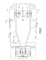
- FIG. 2 is a bottom plan view of the golf car of FIG. 1 ;
- FIG. 3 is a rear elevation view looking forward of a rear drive assembly having the rear coil spring height adjustment device of the present disclosure
- FIG. 4 is a top plan view of the rear drive assembly of FIG. 3 ;
- FIG. 5 is cross sectional elevational view taken at section 5 - 5 of FIG. 3 ;
- FIG. 6 is a partial rear perspective view of the rear drive assembly of FIG. 3 .
- golf car is synonymously used to describe application of the present disclosure to golf cars as well as sport utility vehicles such as modified golf cars, used for example as food and/or beverage cars, golf cars adapted for use as hunting/sporting clays vehicles, golf course maintenance vehicles, and the like.
- a golf car 10 can include a body 12 supported from a structural frame 14 .
- Frame 14 can also support a plurality of wheels including a first steerable wheel 16 and a second steerable wheel 18 .
- powered or driven wheels including a first driven wheel 20 and a second driven wheel 22 are commonly connected to a rear structural portion of frame 14 .
- a front suspension system 23 can also be provided which is adapted for supporting each of the first and second steerable wheels 16 , 18 .
- a rear suspension system 24 can also be provided which is adapted for supporting each of the first and second driven wheels 20 , 22 .
- At least first and second driven wheels 20 , 22 have a diameter 25 , which is distinguishable as a first diameter 25 ′ and a second diameter 25 ′′, the second diameter 25 ′′ greater than the first diameter 25 ′.
- a steering mechanism 26 which commonly includes a steering wheel and a support post assembly is also included to provide the necessary steering input to first and second steerable wheels 16 , 18 .
- Golf car 10 can also include a passenger bench seat 28 and a passenger back support cushion 30 .
- a cover or roof 32 can also be provided which is supported from either body 12 or frame 14 by first and second support members 34 , 36 .
- a windscreen or windshield 38 can also provided which is also supported by each of first and second support members 34 , 36 .
- a rear section of roof 32 can be supported by each of a first and a second rear support element 40 , 42 .
- Other items provided with golf car 10 include golf bag support equipment, accessory racks or bins, headlights, side rails, fenders, and the like.
- Golf car 10 is commonly propelled by a power unit such as an engine or battery/motor system which is commonly provided below and/or behind bench seat 28 . Golf car 10 is capable of motion in either of a forward direction “A” or a rearward direction “B”.
- a power unit such as an engine or battery/motor system which is commonly provided below and/or behind bench seat 28 .
- Golf car 10 is capable of motion in either of a forward direction “A” or a rearward direction “B”.
- Each of first and second driven wheels 20 , 22 can be commonly supported to frame 14 using rear suspension system 24 .
- Each of first and second steerable wheels 16 , 18 can be independently or commonly supported to frame 14 , therefore the present disclosure is not limited by the design of front suspension system 23 .
- frame 14 can further include a longitudinally arranged first frame member 44 and a second frame member 46 .
- First and second frame members 44 , 46 can be hollow, tubular shaped members created of a steel material or similar structural material and formed by welding, extruding, hydroforming, or similar processes.
- a first and second frame connection member 48 , 50 receive distal ends of combined shock absorber/coiled spring assemblies to support each of first and second driven wheels 20 , 22 .
- a first shock support assembly 52 provides installation height adjustment for rear suspension system 24 .
- a second shock support assembly 54 also provides installation height adjustment for rear suspension system 24 .
- Each of first and second shock support assemblies 52 , 54 are connected to an axle housing 56 within which an axle (shown in FIG.
- Axle housing 56 and axle gear housing 57 in part create a rear drive assembly 58 .
- multiple components of the rear drive assembly 58 include axle gear housing 57 which divides axle housing 56 into each of a first housing portion 60 and a second housing portion 62 .
- first wheel mounting plate 64 is connected such as by welding.
- second wheel mounting plate 66 is similarly provided.
- First and second wheel mounting plates 64 , 66 each have one of a first or second wheel hub/brake drum 68 , 70 connected to the mounting plate, for example using a plurality of fasteners 71 .
- An axle 72 is rotatably disposed throughout axle housing 56 which is rotated by axle gear housing 57 to provide the rotating drive for first and second driven wheels 20 , 22 .
- a first shock mount bracket 74 is connected to first housing portion 60 and a second shock mount bracket 76 is connected to second housing portion 62 .
- Each of the shock mount brackets 74 , 76 are fixed in place, for example using a plurality of weld joints 77 .
- First and second shock mount brackets 74 , 76 provide multiple height positions for mounting shock absorbers, which permit multiple height positions for axle housing 56 , and therefore allow for different sizes of first and second driven wheels 20 , 22 .
- First shock mount bracket 74 provides a first height adjustment aperture 78 and a second height adjustment aperture 80 .
- a first shock absorber 82 including a coil spring assembly is connected to first shock mount bracket 74 at either one of first or second height adjustment apertures 78 or 80 .
- First shock absorber 82 includes a first connection sleeve 84 which is connectable to frame 14 .
- First shock absorber 82 further includes a biasing element fixed support plate 86 and a biasing element adjustable support plate 88 between which a biasing element 90 is disposed. Adjusting the position of biasing element adjustable support plate 88 allows the amount of compression provided by biasing element 90 to be controlled thereby adjusting the ride comfort and total weight carrying capacity of golf car 10 .
- second shock mount bracket 76 Similar to first shock mount bracket 74 second shock mount bracket 76 includes a first height adjustment aperture 92 and a second height adjustment aperture 94 .
- a second shock absorber 96 including a coil spring assembly is connected to second shock mount bracket 76 at either of first or second height adjustment apertures 92 or 94 .
- Second shock absorber 96 similar to first shock absorber 82 includes a biasing element fixed support plate 100 , a biasing element adjustable support plate 102 , and a biasing element 104 which each function similar to the corresponding elements of first shock absorber 82 .
- First and second shock support assemblies 52 , 54 are therefore substantially identical to each other in several embodiments of the present disclosure. The present disclosure is not limited to identical installations of first and second shock support assemblies 52 , 54 , as the center of gravity of axle gear housing 57 positioned on axle housing 56 can vary and therefore the load and size of first and second shock support assemblies 52 , 54 can be varied.
- first and second shock mount brackets 74 , 76 each have common members. These include an outer U-shaped member 106 having a first leg 107 joined for example by a bend or a weld to an outer member flange 108 , which is connected by a bend or weld to an opposed second wall 109 . Outer member flange 108 provides various ones of first and second height adjustment apertures 78 , 80 or first and second height adjustment apertures 92 , 94 . First and second legs 107 , 109 of outer U-shaped member 106 are welded or otherwise fixedly connected to an inner U-shaped member 110 .
- Inner U-shaped member 110 is connected for example by welding to one of the first or second housing portions 60 , 62 .
- Each inner U-shaped member 110 includes a third leg 111 connected by a bend or weld to an inner member flange 112 , which is connected by a bend or weld to an opposed fourth leg 113 .
- Inner member flange 112 is similar to outer member flange 108 .
- first and second legs 107 , 109 of outer U-shaped member 106 are welded to inner member flange 112 .
- First and second fastener receiving apertures 114 , 116 are created through inner member flange 112 .
- Each of first and second fastener receiving apertures 114 , 116 are co-axially aligned with corresponding ones of first and second height adjustment apertures 78 , 80 , 92 , or 94 .
- first and second shock absorbers 82 , 96 include a second connection sleeve 118 disposed at an opposite end of the shock absorber from first connection sleeve 84 .
- Second connection sleeve 118 is positioned within a cavity 119 defined by first and second legs 107 , 109 and outer member flange 108 , and inner member flange 112 .
- An aperture of second connection sleeve 118 receives a bolt 120 passed through outer member flange 108 through second connection sleeve 118 and received by inner member flange 112 .
- a first clearance gap “E” and a second clearance gap “F” are provided between second connection sleeve 118 and the inner walls of first and second legs 107 , 109 of the outer U-shaped member 106 .
- First and second clearance gaps “E”, “F” provide clearance for rotation of second connection sleeve 118 within cavity 119 in a direction “G” about an axis of rotation 121 .
- a plurality of weld nuts 122 are fixed for example by tack welding to an axle housing 56 facing side of inner U-shaped member 110 .
- Each of the weld nuts 122 is co-axially aligned with one of the first or second height adjustment apertures 78 , 80 , 92 , or 94 .
- bolts 120 are inserted through second connection sleeve 118 and threaded to a corresponding weld nut 122 .
- each outer member flange 108 can be positioned at an angle ⁇ with respect to a vertical axis 124 defined through the center of axle housing 56 .
- Angle ⁇ matches the orientation of first connection sleeve 84 of first and second shock absorbers 82 , 96 .
- Each inner U-shaped member 110 includes a plurality of ears 126 which are shaped to correspond to an outer diameter of first or second housing portion 60 , 62 .
- the vertical height “H” is provided between the bolt connection location of first connection sleeve 84 and first height adjustment aperture 78 .
- a second vertical height “J” is provided between the bolt connection point of first connection sleeve 84 and second height adjustment aperture 80 .
- the difference between vertical height “H” and second vertical height “J” is predetermined to control an elevation of a longitudinal axis “K” of axle housing 56 to permit height adjustment for rear drive assembly 58 between various platform designs of golf car 10 .
- the plurality of ears 126 are each shaped to correspond to an outer diameter or outer wall shape of first or second housing portion 60 , 62 .
- a semi-circular arc 128 is created, matching a corresponding circular diameter of first and second housing portions 60 , 62 .
- Weld joints 77 are then created to permanently affix each inner U-shaped member 110 to one of the first or second housing portions 60 , 62 .
- a spacing “L” between the first and second height adjustment apertures, in this view apertures 92 , 94 predetermines the height adjustment range for first and second shock absorbers 82 , 96 . In several embodiments, spacing “L” is approximately 1.5 in (3.81 cm).
- Different platforms of golf car 10 can be provided by attaching first and second driven wheels 20 , 22 having first diameter 25 ′ with bolt 120 disposed through one of second height adjustment aperture 80 or 94 , or by using second diameter 25 ′′ with bolt 120 disposed in one of first height adjustment apertures 78 or 92 . Similar wheel diameters can also be used for first and second steerable wheels 16 , 18 . Wheel diameter differences can be used to distinguish, for example, a standard golf car from a food/beverage service car, or a car used for sporting events such as a sporting clays car.
- a biasing compression of biasing element 104 can also be adjusted to affect the height “H” or “J” of the suspension assembly, in combination with selection of one of the first or second height adjustment apertures.
- the biasing element 104 and the shock absorber 82 , 96 together limit the travel of the axle housing 56 relative to frame 14 , and therefore define a travel limit of the rear suspension system 24 .
- Rear coil spring height adjustment devices of the present disclosure provide several advantages. By extending the length of a flange to which a shock absorber sleeve is connected to, various adjustable heights are provided for mounting rear drive assemblies to golf cars having different functions. This also permits a variety of diameter wheels to be installed on the golf car to further vary the vehicle designs that a rear drive assembly of the same design can be installed in. Also, by adjusting the height of installation for shock absorbers using rear coil spring height adjustment devices of the present disclosure, the ride feel of the golf car can also be adjusted.
- connection sleeve of a shock absorber By enclosing the lower or second connection sleeve of a shock absorber within a U-shaped member a bolt connecting the connection sleeve to the rear drive assembly of the golf car is captured at both ends of the connection sleeve which can greatly reduce stresses in the bolted joint.
Landscapes
- Engineering & Computer Science (AREA)
- Mechanical Engineering (AREA)
- Vehicle Body Suspensions (AREA)
- Body Structure For Vehicles (AREA)
Abstract
Description
Claims (28)
Priority Applications (1)
| Application Number | Priority Date | Filing Date | Title |
|---|---|---|---|
| US11/419,396 US7513330B2 (en) | 2006-05-19 | 2006-05-19 | Golf car rear suspension height adjustment |
Applications Claiming Priority (1)
| Application Number | Priority Date | Filing Date | Title |
|---|---|---|---|
| US11/419,396 US7513330B2 (en) | 2006-05-19 | 2006-05-19 | Golf car rear suspension height adjustment |
Publications (2)
| Publication Number | Publication Date |
|---|---|
| US20070267826A1 US20070267826A1 (en) | 2007-11-22 |
| US7513330B2 true US7513330B2 (en) | 2009-04-07 |
Family
ID=38711314
Family Applications (1)
| Application Number | Title | Priority Date | Filing Date |
|---|---|---|---|
| US11/419,396 Active 2027-10-13 US7513330B2 (en) | 2006-05-19 | 2006-05-19 | Golf car rear suspension height adjustment |
Country Status (1)
| Country | Link |
|---|---|
| US (1) | US7513330B2 (en) |
Families Citing this family (3)
| Publication number | Priority date | Publication date | Assignee | Title |
|---|---|---|---|---|
| WO2008115461A2 (en) | 2007-03-16 | 2008-09-25 | Polaris Industries Inc. | Vehicle |
| US10486758B1 (en) * | 2018-05-18 | 2019-11-26 | Yujie Zhang | Golf cart drop axle lift kit |
| US11207933B2 (en) | 2019-08-14 | 2021-12-28 | Yujie Zhang | Golf cart front suspension lift kit |
Citations (6)
| Publication number | Priority date | Publication date | Assignee | Title |
|---|---|---|---|---|
| US4821827A (en) | 1984-05-10 | 1989-04-18 | Club Car, Inc. | Engine mount for golf cart |
| US5275429A (en) * | 1992-04-16 | 1994-01-04 | Donald Bunker | Control arm assembly |
| US5915495A (en) | 1997-04-15 | 1999-06-29 | Club Car, Inc. | Engine and transaxle mounting and suspension system for a vehicle |
| US20050212244A1 (en) | 2004-01-16 | 2005-09-29 | Club Car, Inc. | Adjustable control arm for vehicle suspension mechanisms |
| US20060001223A1 (en) * | 2004-07-01 | 2006-01-05 | Clark Equipment Company | Adjustable height suspension |
| US20070187919A1 (en) * | 2006-02-13 | 2007-08-16 | Textron Inc. | Height adjustment blocks for leaf spring suspension |
-
2006
- 2006-05-19 US US11/419,396 patent/US7513330B2/en active Active
Patent Citations (6)
| Publication number | Priority date | Publication date | Assignee | Title |
|---|---|---|---|---|
| US4821827A (en) | 1984-05-10 | 1989-04-18 | Club Car, Inc. | Engine mount for golf cart |
| US5275429A (en) * | 1992-04-16 | 1994-01-04 | Donald Bunker | Control arm assembly |
| US5915495A (en) | 1997-04-15 | 1999-06-29 | Club Car, Inc. | Engine and transaxle mounting and suspension system for a vehicle |
| US20050212244A1 (en) | 2004-01-16 | 2005-09-29 | Club Car, Inc. | Adjustable control arm for vehicle suspension mechanisms |
| US20060001223A1 (en) * | 2004-07-01 | 2006-01-05 | Clark Equipment Company | Adjustable height suspension |
| US20070187919A1 (en) * | 2006-02-13 | 2007-08-16 | Textron Inc. | Height adjustment blocks for leaf spring suspension |
Also Published As
| Publication number | Publication date |
|---|---|
| US20070267826A1 (en) | 2007-11-22 |
Similar Documents
| Publication | Publication Date | Title |
|---|---|---|
| WO2007095198A1 (en) | Height adjustment blocks for leaf spring suspension | |
| US7392997B2 (en) | Front suspension strut | |
| US7461851B2 (en) | Vehicle, wheel suspension device and method of assembling vehicle | |
| EP3241691A1 (en) | Suspension module having a subframe assembly | |
| EP2879893B1 (en) | Reduced weight axle coupling assembly for vehicle suspension systems | |
| US20120112427A1 (en) | Suspension system for a vehicle | |
| US10118452B2 (en) | Motor vehicle wheel suspension | |
| CN103687779A (en) | Shaft support with integrated bracket for drives | |
| US7648170B2 (en) | Interchangeable suspension system | |
| US6929084B2 (en) | Suspension module for use with an independent suspension including semi-trailing arms with airbag supports | |
| US10086874B2 (en) | Modular vehicle platform and related methods | |
| US20050073124A1 (en) | Independent front wheel suspension, vehicle equipped with such a front wheel suspension, and method of producing a sprung suspension | |
| US20040007843A1 (en) | Suspension trailing arm | |
| US20070267837A1 (en) | Adjustable height front suspension system | |
| US20080067774A1 (en) | Double wishbone front suspension | |
| CN201092243Y (en) | Automobile front suspension structure | |
| US20070267790A1 (en) | Golf car sliding rear leaf spring | |
| US7513330B2 (en) | Golf car rear suspension height adjustment | |
| US20070267259A1 (en) | Rear suspension eyelet mount shock assembly | |
| US20070257463A1 (en) | Reversible a-arm for golf car and off-road utility vehicles | |
| US20070267839A1 (en) | Combination spring, shock and brake cable bracket | |
| US10654523B2 (en) | Vehicle attachment | |
| US20070256881A1 (en) | Threaded inserts used in blind holes in frame tubes | |
| AU2023336525A1 (en) | Axle structure for a utility vehicle chassis, comprising an axle bridge | |
| US20070267838A1 (en) | Symmetrical a-arm for golf car and off-road utility vehicles |
Legal Events
| Date | Code | Title | Description |
|---|---|---|---|
| AS | Assignment |
Owner name: TEXTRON INC., RHODE ISLAND Free format text: ASSIGNMENT OF ASSIGNORS INTEREST;ASSIGNORS:FURMAN, CHRISTOPHER K.;AGERTON, JAMES, II;REEL/FRAME:018667/0850;SIGNING DATES FROM 20061219 TO 20061220 |
|
| STCF | Information on status: patent grant |
Free format text: PATENTED CASE |
|
| CC | Certificate of correction | ||
| AS | Assignment |
Owner name: TEXTRON INNOVATIONS INC., RHODE ISLAND Free format text: ASSIGNMENT OF ASSIGNORS INTEREST;ASSIGNORS:TEXTRON INC.;TEXTRON RHODE ISLAND INC.;REEL/FRAME:022908/0870 Effective date: 20081210 Owner name: TEXTRON INNOVATIONS INC.,RHODE ISLAND Free format text: ASSIGNMENT OF ASSIGNORS INTEREST;ASSIGNORS:TEXTRON INC.;TEXTRON RHODE ISLAND INC.;REEL/FRAME:022908/0870 Effective date: 20081210 |
|
| FPAY | Fee payment |
Year of fee payment: 4 |
|
| FPAY | Fee payment |
Year of fee payment: 8 |
|
| MAFP | Maintenance fee payment |
Free format text: PAYMENT OF MAINTENANCE FEE, 12TH YEAR, LARGE ENTITY (ORIGINAL EVENT CODE: M1553); ENTITY STATUS OF PATENT OWNER: LARGE ENTITY Year of fee payment: 12 |