US7510431B2 - Electrical connector with improved board locks - Google Patents
Electrical connector with improved board locks Download PDFInfo
- Publication number
- US7510431B2 US7510431B2 US11/974,572 US97457207A US7510431B2 US 7510431 B2 US7510431 B2 US 7510431B2 US 97457207 A US97457207 A US 97457207A US 7510431 B2 US7510431 B2 US 7510431B2
- Authority
- US
- United States
- Prior art keywords
- plate
- electrical connector
- body portion
- insulative housing
- mating
- Prior art date
- Legal status (The legal status is an assumption and is not a legal conclusion. Google has not performed a legal analysis and makes no representation as to the accuracy of the status listed.)
- Active
Links
- 230000013011 mating Effects 0.000 claims description 38
- 239000002184 metal Substances 0.000 claims description 16
- 230000014759 maintenance of location Effects 0.000 claims description 5
- 230000000717 retained effect Effects 0.000 claims description 4
- 101100420769 Drosophila melanogaster scaf gene Proteins 0.000 description 1
- 238000010276 construction Methods 0.000 description 1
Images


Classifications
-
- H—ELECTRICITY
- H01—ELECTRIC ELEMENTS
- H01R—ELECTRICALLY-CONDUCTIVE CONNECTIONS; STRUCTURAL ASSOCIATIONS OF A PLURALITY OF MUTUALLY-INSULATED ELECTRICAL CONNECTING ELEMENTS; COUPLING DEVICES; CURRENT COLLECTORS
- H01R12/00—Structural associations of a plurality of mutually-insulated electrical connecting elements, specially adapted for printed circuits, e.g. printed circuit boards [PCB], flat or ribbon cables, or like generally planar structures, e.g. terminal strips, terminal blocks; Coupling devices specially adapted for printed circuits, flat or ribbon cables, or like generally planar structures; Terminals specially adapted for contact with, or insertion into, printed circuits, flat or ribbon cables, or like generally planar structures
- H01R12/70—Coupling devices
- H01R12/7005—Guiding, mounting, polarizing or locking means; Extractors
- H01R12/7011—Locking or fixing a connector to a PCB
- H01R12/7017—Snap means
- H01R12/7029—Snap means not integral with the coupling device
-
- H—ELECTRICITY
- H01—ELECTRIC ELEMENTS
- H01R—ELECTRICALLY-CONDUCTIVE CONNECTIONS; STRUCTURAL ASSOCIATIONS OF A PLURALITY OF MUTUALLY-INSULATED ELECTRICAL CONNECTING ELEMENTS; COUPLING DEVICES; CURRENT COLLECTORS
- H01R13/00—Details of coupling devices of the kinds covered by groups H01R12/70 or H01R24/00 - H01R33/00
- H01R13/46—Bases; Cases
- H01R13/502—Bases; Cases composed of different pieces
- H01R13/508—Bases; Cases composed of different pieces assembled by a separate clip or spring
-
- H—ELECTRICITY
- H01—ELECTRIC ELEMENTS
- H01R—ELECTRICALLY-CONDUCTIVE CONNECTIONS; STRUCTURAL ASSOCIATIONS OF A PLURALITY OF MUTUALLY-INSULATED ELECTRICAL CONNECTING ELEMENTS; COUPLING DEVICES; CURRENT COLLECTORS
- H01R13/00—Details of coupling devices of the kinds covered by groups H01R12/70 or H01R24/00 - H01R33/00
- H01R13/648—Protective earth or shield arrangements on coupling devices, e.g. anti-static shielding
- H01R13/658—High frequency shielding arrangements, e.g. against EMI [Electro-Magnetic Interference] or EMP [Electro-Magnetic Pulse]
- H01R13/6591—Specific features or arrangements of connection of shield to conductive members
- H01R13/6594—Specific features or arrangements of connection of shield to conductive members the shield being mounted on a PCB and connected to conductive members
- H01R13/6595—Specific features or arrangements of connection of shield to conductive members the shield being mounted on a PCB and connected to conductive members with separate members fixing the shield to the PCB
Definitions
- the present invention relates to an electrical connector, and more particularly to an electrical connector with improved board locks.
- U.S. Pat. No. 6,012,954 discloses a conventional electrical connector which comprises an insulative housing, a plurality of terminals received in the insulative housing, a shell partially enclosing the housing, a pair of board locks and a pair of fasteners for assembling the board locks onto the housing.
- Each fastener has a first plate and a hollow cylinder extending from the first plate.
- the hollow cylinder extends through a through hole of the board lock with the first plate to abut against the board lock on a rear side of the insulative housing.
- the hollow cylinder further extends through the housing and the shell to abutting against a front surface. Therefore, the housing, the shell, and the board lock are secured together by the fastener.
- the connector needs a fastener to be assembled as a whole and to establish a grounding path between the shell and the board lock, the number of the elements of the connector is increased and complicated the structure of the connector. As a result, the cost of the connector is also increased.
- a main object of the present invention is to provide an electrical connector with improved board lock for easy assembly and reducing cost.
- an electrical connector comprises an insulative housing, a plurality of contacts retained in the insulative housing, a metal shell shielding the insulative housing, and a pair of board locks.
- the insulative housing has a body portion and a mating portion. The body portion defines a pair of receiving spaces extending therethrough.
- Each board locks comprises a first plate with a hollow cylinder, a hook section extending out of the insulative housing, and a connect section connect the first plate with the hook section.
- the metal shell defines a pair of through holes corresponding to the hollow cylinders respectively. The metal shell and the insulative housing sandwich the first plates of the board locks therebetween.
- the body portion and mating portion of the insulative housing can be separated.
- the electrical connector further comprises a full-proofing device for insuring the body portion and mating portion mating with each other accurately.
- the full-proofing device is arranged only on one side of the electrical connector and includes a post and a slit fitting with each other. The post and the slit being arranged on the body portion and the mating portion respectively.
- FIG. 1 is a perspective view of an electrical connector according to the present invention
- FIG. 2 is a perspective view of the electrical connector shown in FIG. 1 , showing the metal shell detaching from the housing;
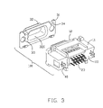
- FIG. 3 is similar to FIG. 2 , but viewed from another aspect
- FIG. 4 is an exploded view of the electrical connector shown in FIG. 1 ;
- FIG. 5 is similar to FIG. 4 , but viewed from another aspect.
- an electrical connector 100 includes an insulative housing 10 , a plurality of contacts 20 retained in the insulative housing 10 , a metal shell 30 partially enclosing the insulative housing 10 , and a pair of integrated board locks 40 .
- the insulative housing 10 having a body portion 11 and a mating portion 12 apart from the body portion 11 .
- the body portion 10 has a front face 110 for contacting with the shell 30 and a rear face 111 opposite to the front face 110 for mounting a mother board (not shown).
- the body portion 11 defines a central space 13 opening to the front face 110 for receiving the mating portion 12 therein.
- the body portion 11 further defines a pair of receiving spaces 14 extending therethrough at lateral sides thereof. Each receiving spaces 14 comprises a first recess 141 and a second recess 142 .
- the body portion 11 defines a plurality of through holes 112 behind the central space 13 .
- the mating portion 12 includes a base plate 121 , a front section 122 extending forwardly from the base plate 121 , and a rear section 123 opposite to the front section 122 .
- the mating portion 12 defines a plurality of passageways 124 extending therethrough and corresponding to the through holes 112 .
- the body portion 11 and the mating portion 12 each defines a mating face 113 , 125 contacting with each other.
- the insulative housing 10 further comprises a full-proofing device thereonon.
- the full-proofing device includes a post 114 and a slit 126 mating with each other.
- the post 114 is projecting from the mating face 113 to the front face 110 of the body portion 11 .
- the slit 126 is defines on the mating face 125 of the mating portion 12 .
- the post 114 and the slit 126 are only arranged on one side of the insulative housing 10 thereby the body portion 11 and the mating portion 12 can accurately mate with each other and avoid the electrical contacts 20 inserting into the insulative housing 10 by error.
- Each electrical contacts 20 comprises a retention section 21 engaging with the passageways 124 of the mating portion 12 , a contact section 22 extending forwardly from the retention section 21 , and a mounting section 23 connecting with the retention section 21 .
- the mounting section 23 is received in the through holes 112 and projects out of the rear face 111 of the body portion 11 .
- the board locks 40 are received in the receiving spaces 14 of the body portion 11 and each comprises a first plate 41 , a hook section 42 extending out of the insulative housing 10 , and a connect section 43 connecting the first plate 41 with the hook section 42 .
- the first plate 41 includes a hollow cylinder 44 .
- the connect section 43 comprises a second plate 45 extending vertically from a side edge of the first plate 41 and a third plate 46 parallel to the first plate 41 .
- the hook section 42 is connected with the third plate 41 and perpendicular thereto.
- the second and third plate 45 , 46 each include a rib 47 thereon for abutting to the body portion 11 .
- the first plate 41 is received in the first recess 141 and the connect section 43 and the hollow cylinder 44 are received in the second recess 142 .
- the metal shell 3 comprises a flat portion 31 to be attached to the front surface 110 of the body portion 11 and a D-shaped projection 32 protruding forwardly from the mating portion 31 .
- the mating portion 31 defines a pair of through holes 33 on lateral sides thereof and corresponding to the hollow cylinder 44 of the board lock 40 .
- the projection 32 is hollow to define a chamber 320 therein for the front section 123 of the mating portion 12 extending therein.
- the metal shell 30 also comprises a plurality of retention barbs 34 at top and bottom edge thereof for securing the shell 30 to the insulative housing 10 .
- the first plate 41 of the board lock 40 is coplanar with the front face 110 of the body portion 11 and contacts with the flat portion 31 of the metal shell 30 .
- the first plates 41 of the board locks 40 are sandwiched by the metal shell 30 and the insulative housing 10 directly without additional fasteners which not only simplify the construction of the electrical connector 100 but also the facilitating the assembly of the electrical connector 100 .
Landscapes
- Details Of Connecting Devices For Male And Female Coupling (AREA)
- Connector Housings Or Holding Contact Members (AREA)
Abstract
Description
Claims (20)
Applications Claiming Priority (2)
| Application Number | Priority Date | Filing Date | Title |
|---|---|---|---|
| CN200620126459.7 | 2006-10-16 | ||
| CNU2006201264597U CN200972951Y (en) | 2006-10-16 | 2006-10-16 | Electric connector |
Publications (2)
| Publication Number | Publication Date |
|---|---|
| US20080090455A1 US20080090455A1 (en) | 2008-04-17 |
| US7510431B2 true US7510431B2 (en) | 2009-03-31 |
Family
ID=38884202
Family Applications (1)
| Application Number | Title | Priority Date | Filing Date |
|---|---|---|---|
| US11/974,572 Active US7510431B2 (en) | 2006-10-16 | 2007-10-15 | Electrical connector with improved board locks |
Country Status (3)
| Country | Link |
|---|---|
| US (1) | US7510431B2 (en) |
| JP (1) | JP3138297U (en) |
| CN (1) | CN200972951Y (en) |
Cited By (5)
| Publication number | Priority date | Publication date | Assignee | Title |
|---|---|---|---|---|
| US20090098751A1 (en) * | 2007-10-12 | 2009-04-16 | Hon Hai Precision Ind. Co., Ltd. | Electrical connector having board lock |
| US20090197473A1 (en) * | 2008-02-05 | 2009-08-06 | Asustek Computer Inc. | Electronic device and connector thereof |
| US20100068932A1 (en) * | 2008-09-15 | 2010-03-18 | Chou Hsien Tsai | Electrical connector with metal sheath |
| US20120322292A1 (en) * | 2011-06-20 | 2012-12-20 | Hon Hai Precision Industry Co., Ltd. | Electrical connector assembly equipped with enhanced locking mechanism thereon |
| US20140187064A1 (en) * | 2012-12-28 | 2014-07-03 | Alltop Electronics (Suzhou) Co., Ltd. | Low-profile electrical connector with improved mounting pieces for resisting impact force |
Families Citing this family (5)
| Publication number | Priority date | Publication date | Assignee | Title |
|---|---|---|---|---|
| DE102008034113A1 (en) * | 2008-07-21 | 2010-02-04 | Phoenix Contact Gmbh & Co. Kg | Electric connecting device i.e. plug-type connecting device, for transmitting electric power for controlling and operating servomotor, has latching device comprising latching unit arranged inclined to base surface of shielding plate |
| CN105098393A (en) * | 2014-04-24 | 2015-11-25 | 富士康(昆山)电脑接插件有限公司 | Electric connector |
| DE102014109351B3 (en) * | 2014-07-04 | 2015-07-30 | Harting Electric Gmbh & Co. Kg | Connector with protective conductor bridge |
| CN108173063A (en) * | 2018-02-09 | 2018-06-15 | 东莞市扬志精密五金有限公司 | A kind of needle stand waterproof male and female head |
| CN109259421A (en) * | 2018-07-10 | 2019-01-25 | 浙江捷昌线性驱动科技股份有限公司 | Plug-in control device and lifting platform |
Citations (4)
| Publication number | Priority date | Publication date | Assignee | Title |
|---|---|---|---|---|
| US5807135A (en) * | 1996-02-29 | 1998-09-15 | Berg Technology, Inc. | Method for mounting a right angled connector on a printed circuit board |
| US6012954A (en) | 1998-08-07 | 2000-01-11 | Hon Hai Precision Ind. Co., Ltd. | Electrical connector |
| US6379181B1 (en) * | 2000-12-07 | 2002-04-30 | Hon Hai Precision Ind. Co., Ltd. | Electrical connector having locking device |
| US6386910B1 (en) * | 2000-08-17 | 2002-05-14 | Advanced Connecteck Inc. | Electrical connector |
-
2006
- 2006-10-16 CN CNU2006201264597U patent/CN200972951Y/en not_active Expired - Lifetime
-
2007
- 2007-10-15 JP JP2007007907U patent/JP3138297U/en not_active Expired - Fee Related
- 2007-10-15 US US11/974,572 patent/US7510431B2/en active Active
Patent Citations (4)
| Publication number | Priority date | Publication date | Assignee | Title |
|---|---|---|---|---|
| US5807135A (en) * | 1996-02-29 | 1998-09-15 | Berg Technology, Inc. | Method for mounting a right angled connector on a printed circuit board |
| US6012954A (en) | 1998-08-07 | 2000-01-11 | Hon Hai Precision Ind. Co., Ltd. | Electrical connector |
| US6386910B1 (en) * | 2000-08-17 | 2002-05-14 | Advanced Connecteck Inc. | Electrical connector |
| US6379181B1 (en) * | 2000-12-07 | 2002-04-30 | Hon Hai Precision Ind. Co., Ltd. | Electrical connector having locking device |
Cited By (9)
| Publication number | Priority date | Publication date | Assignee | Title |
|---|---|---|---|---|
| US20090098751A1 (en) * | 2007-10-12 | 2009-04-16 | Hon Hai Precision Ind. Co., Ltd. | Electrical connector having board lock |
| US7682190B2 (en) * | 2007-10-12 | 2010-03-23 | Hon Hai Precision Ind. Co., Ltd. | Electrical connector having board lock |
| US20090197473A1 (en) * | 2008-02-05 | 2009-08-06 | Asustek Computer Inc. | Electronic device and connector thereof |
| US7775830B2 (en) * | 2008-02-05 | 2010-08-17 | Asustek Computer Inc. | Connector with metal fixing element and electronic device having the same |
| US20100068932A1 (en) * | 2008-09-15 | 2010-03-18 | Chou Hsien Tsai | Electrical connector with metal sheath |
| US20120322292A1 (en) * | 2011-06-20 | 2012-12-20 | Hon Hai Precision Industry Co., Ltd. | Electrical connector assembly equipped with enhanced locking mechanism thereon |
| US8840421B2 (en) * | 2011-06-20 | 2014-09-23 | Hon Hai Precision Industry Co., Ltd. | Electrical connector assembly equipped with enhanced locking mechanism thereon |
| US20140187064A1 (en) * | 2012-12-28 | 2014-07-03 | Alltop Electronics (Suzhou) Co., Ltd. | Low-profile electrical connector with improved mounting pieces for resisting impact force |
| US9004927B2 (en) * | 2012-12-28 | 2015-04-14 | Alltop Electronics (Suzhou) Ltd. | Low-profile electrical connector with improved mounting pieces for resisting impact force |
Also Published As
| Publication number | Publication date |
|---|---|
| JP3138297U (en) | 2007-12-27 |
| US20080090455A1 (en) | 2008-04-17 |
| CN200972951Y (en) | 2007-11-07 |
Similar Documents
| Publication | Publication Date | Title |
|---|---|---|
| US7510431B2 (en) | Electrical connector with improved board locks | |
| US8753145B2 (en) | Guide frame with two columns connected by cross pieces defining an opening with retention members | |
| US9847604B2 (en) | Electrical connector having improved shielding structure | |
| US6210218B1 (en) | Electrical connector | |
| US7491083B2 (en) | Electrical connector assembly | |
| US6589077B1 (en) | Electrical connector with self-retaining board locks | |
| US7052322B2 (en) | Stacked electrical connector | |
| US7473121B2 (en) | Electrical connector assembly having connecting portion | |
| US7578696B2 (en) | Electrical connector with cover configured for heat dissipation | |
| US7658624B2 (en) | Electrical connector assembly having contacts without soldering legs | |
| US20080014798A1 (en) | Electrical connector having improved outer shield | |
| US7351106B2 (en) | Electrical connector having an inner printed circuit board | |
| US20080020640A1 (en) | Electrical connector with shell | |
| US7232316B2 (en) | Electrical connector with improved shielding means | |
| US20090191727A1 (en) | Electrical connector having improved terminal module | |
| US6089916A (en) | Cable assembly connector | |
| US7517233B2 (en) | Electrical connector with improved fastener | |
| US20060116007A1 (en) | Socket connector for carrying integrated circuit package | |
| US20050153585A1 (en) | Card edge connector | |
| US6923679B1 (en) | Cable assembly floatably mounted on a panel | |
| US20080020642A1 (en) | Electrical connector having improved inner shileding plate | |
| US8282400B2 (en) | Electronic connector with grounding metal plate | |
| US6293825B1 (en) | Electrical connector | |
| US20030082935A1 (en) | Circuit board-to-board interconnection device | |
| US20120077367A1 (en) | Cable assembly with an improved shell |
Legal Events
| Date | Code | Title | Description |
|---|---|---|---|
| AS | Assignment |
Owner name: HON HAI PRESCISION IND. CO., LTD., TAIWAN Free format text: ASSIGNMENT OF ASSIGNORS INTEREST;ASSIGNORS:ZHU, ZI-QIANG;XIANG, XING-HAI;CHEN, KAI;AND OTHERS;REEL/FRAME:020029/0536 Effective date: 20071010 |
|
| STCF | Information on status: patent grant |
Free format text: PATENTED CASE |
|
| FPAY | Fee payment |
Year of fee payment: 4 |
|
| FPAY | Fee payment |
Year of fee payment: 8 |
|
| MAFP | Maintenance fee payment |
Free format text: PAYMENT OF MAINTENANCE FEE, 12TH YEAR, LARGE ENTITY (ORIGINAL EVENT CODE: M1553); ENTITY STATUS OF PATENT OWNER: LARGE ENTITY Year of fee payment: 12 |