US7509809B2 - Gas turbine engine combustor with improved cooling - Google Patents
Gas turbine engine combustor with improved cooling Download PDFInfo
- Publication number
- US7509809B2 US7509809B2 US11/149,264 US14926405A US7509809B2 US 7509809 B2 US7509809 B2 US 7509809B2 US 14926405 A US14926405 A US 14926405A US 7509809 B2 US7509809 B2 US 7509809B2
- Authority
- US
- United States
- Prior art keywords
- cooling
- combustor
- regions
- liner
- annular
- Prior art date
- Legal status (The legal status is an assumption and is not a legal conclusion. Google has not performed a legal analysis and makes no representation as to the accuracy of the status listed.)
- Active, expires
Links
Images


Classifications
-
- F—MECHANICAL ENGINEERING; LIGHTING; HEATING; WEAPONS; BLASTING
- F02—COMBUSTION ENGINES; HOT-GAS OR COMBUSTION-PRODUCT ENGINE PLANTS
- F02C—GAS-TURBINE PLANTS; AIR INTAKES FOR JET-PROPULSION PLANTS; CONTROLLING FUEL SUPPLY IN AIR-BREATHING JET-PROPULSION PLANTS
- F02C3/00—Gas-turbine plants characterised by the use of combustion products as the working fluid
- F02C3/14—Gas-turbine plants characterised by the use of combustion products as the working fluid characterised by the arrangement of the combustion chamber in the plant
-
- F—MECHANICAL ENGINEERING; LIGHTING; HEATING; WEAPONS; BLASTING
- F23—COMBUSTION APPARATUS; COMBUSTION PROCESSES
- F23R—GENERATING COMBUSTION PRODUCTS OF HIGH PRESSURE OR HIGH VELOCITY, e.g. GAS-TURBINE COMBUSTION CHAMBERS
- F23R3/00—Continuous combustion chambers using liquid or gaseous fuel
- F23R3/02—Continuous combustion chambers using liquid or gaseous fuel characterised by the air-flow or gas-flow configuration
- F23R3/04—Air inlet arrangements
- F23R3/06—Arrangement of apertures along the flame tube
-
- F—MECHANICAL ENGINEERING; LIGHTING; HEATING; WEAPONS; BLASTING
- F23—COMBUSTION APPARATUS; COMBUSTION PROCESSES
- F23R—GENERATING COMBUSTION PRODUCTS OF HIGH PRESSURE OR HIGH VELOCITY, e.g. GAS-TURBINE COMBUSTION CHAMBERS
- F23R3/00—Continuous combustion chambers using liquid or gaseous fuel
- F23R3/42—Continuous combustion chambers using liquid or gaseous fuel characterised by the arrangement or form of the flame tubes or combustion chambers
- F23R3/50—Combustion chambers comprising an annular flame tube within an annular casing
-
- F—MECHANICAL ENGINEERING; LIGHTING; HEATING; WEAPONS; BLASTING
- F23—COMBUSTION APPARATUS; COMBUSTION PROCESSES
- F23R—GENERATING COMBUSTION PRODUCTS OF HIGH PRESSURE OR HIGH VELOCITY, e.g. GAS-TURBINE COMBUSTION CHAMBERS
- F23R3/00—Continuous combustion chambers using liquid or gaseous fuel
- F23R3/42—Continuous combustion chambers using liquid or gaseous fuel characterised by the arrangement or form of the flame tubes or combustion chambers
- F23R3/54—Reverse-flow combustion chambers
-
- F—MECHANICAL ENGINEERING; LIGHTING; HEATING; WEAPONS; BLASTING
- F05—INDEXING SCHEMES RELATING TO ENGINES OR PUMPS IN VARIOUS SUBCLASSES OF CLASSES F01-F04
- F05D—INDEXING SCHEME FOR ASPECTS RELATING TO NON-POSITIVE-DISPLACEMENT MACHINES OR ENGINES, GAS-TURBINES OR JET-PROPULSION PLANTS
- F05D2260/00—Function
- F05D2260/20—Heat transfer, e.g. cooling
- F05D2260/202—Heat transfer, e.g. cooling by film cooling
-
- F—MECHANICAL ENGINEERING; LIGHTING; HEATING; WEAPONS; BLASTING
- F23—COMBUSTION APPARATUS; COMBUSTION PROCESSES
- F23R—GENERATING COMBUSTION PRODUCTS OF HIGH PRESSURE OR HIGH VELOCITY, e.g. GAS-TURBINE COMBUSTION CHAMBERS
- F23R2900/00—Special features of, or arrangements for continuous combustion chambers; Combustion processes therefor
- F23R2900/03041—Effusion cooled combustion chamber walls or domes
-
- F—MECHANICAL ENGINEERING; LIGHTING; HEATING; WEAPONS; BLASTING
- F23—COMBUSTION APPARATUS; COMBUSTION PROCESSES
- F23R—GENERATING COMBUSTION PRODUCTS OF HIGH PRESSURE OR HIGH VELOCITY, e.g. GAS-TURBINE COMBUSTION CHAMBERS
- F23R2900/00—Special features of, or arrangements for continuous combustion chambers; Combustion processes therefor
- F23R2900/03042—Film cooled combustion chamber walls or domes
Definitions
- the invention relates generally to a combustor of a gas turbine engine and, more particularly, to a combustor having improved cooling.
- Cooling of combustor walls is typically achieved by directing cooling air through holes in the combustor wall to provide effusion and/or film cooling. These holes may be provided as effusion cooling holes formed directly through a sheet metal liner of the combustor walls. Opportunities for improvement are continuously sought, however, to provide improve cooling, better mixing of the cooling air, better fuel efficiency and improved performance, all while reducing costs.
- the present invention provides a gas turbine engine combustor comprising a liner enclosing a combustion chamber, the liner including a dome portion at an upstream end thereof and at least one annular liner wall extending downstream from and circumscribing said dome portion, the dome portion having defined therein a plurality of openings each adapted to receive a fuel nozzle, said liner wall having a plurality of holes defined therein to form an annular cooling band extending around said liner wall immediately downstream of said dome portion for directing cooling air into the combustion chamber, said plurality of holes within said annular cooling band including a first set of cooling holes disposed within circumferentially spaced regions aligned with said openings and located downstream therefrom and a second set of cooling holes disposed outside said regions, wherein said regions having said first set of cooling holes provide a greater cooling air flow therethrough than similarly sized areas of said combustor liner having said second set of cooling holes therein.
- the present invention provides a gas turbine engine combustor comprising an annular liner enclosing a combustion chamber, the liner having defined therein a plurality of openings each adapted to receive a fuel nozzle for directing fuel into the combustion chamber in a spray cone, the liner having means for directing cooling air into the combustion chamber, said means providing more cooling air in regions corresponding substantially in shape to said spray cone and located downstream of each opening in alignment therewith.
- the present invention provides a combustor for a gas turbine engine comprising: combustor walls including an inner liner and an outer liner spaced apart to define at least a portion of a combustion chamber therebetween; a plurality of fuel nozzles disposed at an end of the combustor between said inner and outer liners for injecting a spray cone of fuel mixture into the combustion chamber; and a plurality of cooling apertures defined through at least one of said inner and outer liners for delivering pressurized cooling air surrounding said combustor into said combustion chamber, said plurality of cooling apertures defining an annular cooling band extending around said at least one of said inner and outer liners immediately downstream from said end of the combustor having said fuel nozzles, said cooling apertures being disposed in a first spacing density in first regions of said annular cooling band proximate each of said fuel nozzles and defining a surface area corresponding substantially in shape to the spray cone of said fuel nozzles, said cooling apertures being disposed in a second spacing density in at
- FIG. 1 is a schematic partial cross-section of a gas turbine engine
- FIG. 2 is partial cross-section of a reverse flow annular combustor having cooling holes at an upstream end thereof in accordance with one aspect of the present invention
- FIG. 3 is a partial perspective view of an annular wall portion of the combustor of FIG. 2 at said upstream end;
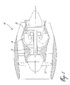
- FIG. 4 is a schematic partial top elevation view of the combustor of FIG. 2 .
- FIG. 1 illustrates a gas turbine engine 10 of a type preferably provided for use in subsonic flight, generally comprising in serial flow communication a fan 12 through which ambient air is propelled, a multistage compressor 14 for pressurizing the air, a combustor 16 in which the compressed air is mixed with fuel and ignited for generating an annular stream of hot combustion gases, and a turbine section 18 for extracting energy from the combustion gases.
- a gas turbine engine 10 of a type preferably provided for use in subsonic flight, generally comprising in serial flow communication a fan 12 through which ambient air is propelled, a multistage compressor 14 for pressurizing the air, a combustor 16 in which the compressed air is mixed with fuel and ignited for generating an annular stream of hot combustion gases, and a turbine section 18 for extracting energy from the combustion gases.
- the combustor 16 is housed in a plenum 20 defined partially by a gas generator case 22 and supplied with compressed air from compressor 14 by a diffuser 24 .
- the combustor 16 is preferably, but not necessarily, an annular reverse flow combustor.
- Combustor 16 comprises generally a liner 26 composed of an outer liner 26 A and an inner liner 26 B defining a combustion chamber 32 therein.
- Combustor 16 preferably has a generally dome portion 34 , as will be described in more detail below.
- Outer liner 26 A includes an outer dome panel portion 34 A, a relatively small radius transition portion 36 A, a cylindrical wall portion 38 A, long exit duct portion 40 A, while inner liner 26 B includes an inner dome panel portion 34 B, a relatively small radius transition portion 36 B, a cylindrical wall portion 38 B, and a small exit duct portion 40 B.
- the exit ducts 40 A and 40 B together define a combustor exit 42 for communicating with turbine section 18 .
- the combustor liner 26 is preferably sheet metal.
- a plurality of cooling holes 44 are provided in liner 26 , more particularly in the upstream end of the cylindrical body panel portions 38 A, 38 B thereof, as will be described in further detail below.
- a plurality of air-guided fuel nozzles 50 having supports 52 and supplied with fuel from internal manifold 54 , communicate with the combustion chamber 32 to deliver a fuel-air mixture 58 to the chamber 32 .
- the fuel-air mixture is delivered in a cone-shaped spray pattern, and therefore referred to in this application as fuel spray cone 58 .
- compressed air enters plenum 20 from diffuser 24 .
- the air circulates around combustor 16 and eventually enters combustion chamber 32 through a variety of apertures defined in the liner 26 , following which some of the compressed air is mixed with fuel for combustion. Combustion gases are exhausted through the combustor exit 42 to the turbine section 18 .
- the air flow apertures defined in the liner include the plurality of cooling holes 44 in an upstream end of the liner 26 .
- compressed air from the plenum 20 also enters the combustion chamber via other apertures in the combustor liner 26 , such as combustion air flow apertures, including openings 56 surrounding the fuel nozzles 50 and fuel nozzle air flow passages 57 , and a plurality of other cooling apertures (not shown) which may be provided throughout the liner 26 for effusion/film cooling of the liner walls. Therefore while only the upstream cooling holes 44 are depicted, a variety of other apertures may be provided in the liner for cooling purposes and/or for injecting combustion air into the combustion chamber.
- the combustor liner 26 includes a plurality of cooling air holes 44 formed in the upstream end of the cylindrical wall portions 38 A, 38 B, such that effusion cooling is achieved at this upstream end of the combustor 16 by directing air though the cooling holes 44 .
- the plurality of cooling holes 44 are preferably angled downstream, such that they direct the cooling air flowing therethrough along the inner surfaces of the cylindrical wall portions 38 A, B of the combustor liner and such that the cooling air is generally prevented from being ignited.
- all such cooling holes 44 are disposed at an angle of less than about 28 degrees relative to the inner surface of the cylindrical liner walls 38 A, 38 B.
- the plurality of cooling holes 44 comprise an annular band 45 of cooling holes which extend around each of the cylindrical wall portions 38 A, 38 B, and which axially (relative to the engine axis) begin at an upstream end thereof near the rounded transition wall portions 36 A, 36 B and extend downstream a given distance.
- the transition portions 36 A, B are frustoconical with relatively small radii connections to their respective dome and cylindrical wall panels, however other wall geometries may also be employed.
- the plurality of cooling holes 44 are comprised generally of at least two main groups, namely first cooling holes 46 and second cooling holes 48 .
- the first and second cooling holes 46 , 48 are arranged in the liner in a selected pattern such that increased cooling air is provided to regions 60 identified as being regions of local high temperature.
- the regions 60 of first cooling holes 46 are aligned with each opening 45 in the dome portion 34 of the liner which receive the fuel nozzles 50 therein, and define a truncated wedge or triangular shape, wherein the cooling holes 46 fan out downstream from the rounded transition wall portions 36 A, 36 B.
- the regions 60 define a trapezoidal perimeter in which the upstream and downstream edges are parallel, the upstream edge being shorter than the downstream edge.
- first cooling holes 46 are thus formed to correspond to the fuel spray cone 58 ejected into the combustion chamber by the fuel nozzles 50 which, when ignited, exposes the regions 60 of the liner 26 to particularly high temperatures. While other shapes of regions 60 may be employed, these will nonetheless preferably correspond to identified regions of local high temperature of the liner walls downstream of the fuel nozzles caused by the proximity of the ignited fuel mixture ejected therefrom.
- first cooling holes 46 are defined within the regions 60 in alignment with each fuel nozzle 50 and preferably corresponding in shape to the fuel spray cone 58
- the second cooling holes 48 are defined in the liner wall outside of these regions 60 , at least between each adjacent region 60 within the annular band 45 about the upstream end of the combustor liner 26 .
- first cooling holes 46 are provided within regions 60 of the liner to cool these areas of the liner which are exposed to the highest temperatures.
- this is accomplished by spacing the first cooling holes 46 , within the regions 60 , closer together than the second cooling holes 48 .
- the first cooling holes 46 are formed in the liner at a higher spacing density relative to the spacing density of the second cooling holes 48 .
- the diameters of the first cooling holes 46 and the second cooling holes 48 are substantially the same, however more first cooling holes 46 are disposed in a given area of liner wall within the regions 60 than second cooling holes 48 in a similarly sized area of the liner wall outside the regions 60 .
- first and second cooling holes may be the same if the diameters of the first cooling holes 46 are larger than those of the second cooling holes 48 , or both the spacing density and the diameters of the first and second cooling holes may be different.
- the regions 60 of the combustor liner cylindrical walls 38 A, 38 B for such a small combustor 16 are provided with more localized and directed cooling than other regions of the combustor liner, which are less prone to fuel impingement from the fuel spray cone 58 .
- This is at least partly achieved using the regions 60 of first cooling apertures 46 defined within the regions 60 , which direct an optimized volume of coolant to these regions and in a direction which will not adversely effecting the combustion of the air-fuel mixture within the combustion chamber (i.e. by preventing the coolant air from being used as combustion air).
- the combustor liner 26 is preferably provided in sheet metal and the plurality of cooling holes 44 are preferably drilled in the sheet metal, such as by laser drilling.
- the plurality of cooling holes 44 are preferably drilled in the sheet metal, such as by laser drilling.
- other known combustor materials and construction methods are also possible.
- first and second holes may be provided on one side of the dome only (e.g. annular outside), but not the other (i.e. annular inside), or vice versa. Still other modifications which fall within the scope of the present invention will be apparent to those skilled in the art, in light of a review of this disclosure, and such modifications are intended to fall within the literal scope of the appended claims.
Landscapes
- Engineering & Computer Science (AREA)
- Chemical & Material Sciences (AREA)
- Combustion & Propulsion (AREA)
- Mechanical Engineering (AREA)
- General Engineering & Computer Science (AREA)
- Turbine Rotor Nozzle Sealing (AREA)
- Spray-Type Burners (AREA)
Abstract
Description
Claims (18)
Priority Applications (2)
| Application Number | Priority Date | Filing Date | Title |
|---|---|---|---|
| US11/149,264 US7509809B2 (en) | 2005-06-10 | 2005-06-10 | Gas turbine engine combustor with improved cooling |
| CA2546881A CA2546881C (en) | 2005-06-10 | 2006-05-15 | Gas turbine engine combustor with improved cooling |
Applications Claiming Priority (1)
| Application Number | Priority Date | Filing Date | Title |
|---|---|---|---|
| US11/149,264 US7509809B2 (en) | 2005-06-10 | 2005-06-10 | Gas turbine engine combustor with improved cooling |
Publications (2)
| Publication Number | Publication Date |
|---|---|
| US20060277921A1 US20060277921A1 (en) | 2006-12-14 |
| US7509809B2 true US7509809B2 (en) | 2009-03-31 |
Family
ID=37522858
Family Applications (1)
| Application Number | Title | Priority Date | Filing Date |
|---|---|---|---|
| US11/149,264 Active 2027-04-03 US7509809B2 (en) | 2005-06-10 | 2005-06-10 | Gas turbine engine combustor with improved cooling |
Country Status (2)
| Country | Link |
|---|---|
| US (1) | US7509809B2 (en) |
| CA (1) | CA2546881C (en) |
Cited By (17)
| Publication number | Priority date | Publication date | Assignee | Title |
|---|---|---|---|---|
| US20110023495A1 (en) * | 2009-07-30 | 2011-02-03 | Honeywell International Inc. | Effusion cooled dual wall gas turbine combustors |
| US20120180499A1 (en) * | 2011-01-14 | 2012-07-19 | General Electric Company | Power generation system |
| US8572986B2 (en) | 2009-07-27 | 2013-11-05 | United Technologies Corporation | Retainer for suspended thermal protection elements in a gas turbine engine |
| US20140260260A1 (en) * | 2013-03-12 | 2014-09-18 | Pratt & Whitney Canada Corp. | Combustor for gas turbine engine |
| US9228747B2 (en) | 2013-03-12 | 2016-01-05 | Pratt & Whitney Canada Corp. | Combustor for gas turbine engine |
| US9366187B2 (en) | 2013-03-12 | 2016-06-14 | Pratt & Whitney Canada Corp. | Slinger combustor |
| US9447974B2 (en) | 2012-09-13 | 2016-09-20 | United Technologies Corporation | Light weight swirler for gas turbine engine combustor and a method for lightening a swirler for a gas turbine engine |
| US9958152B2 (en) | 2014-08-14 | 2018-05-01 | Siemens Aktiengesellschaft | Multi-functional fuel nozzle with an atomizer array |
| US9958161B2 (en) | 2013-03-12 | 2018-05-01 | Pratt & Whitney Canada Corp. | Combustor for gas turbine engine |
| US20180266687A1 (en) * | 2017-03-16 | 2018-09-20 | General Electric Company | Reducing film scrubbing in a combustor |
| US20180299127A1 (en) * | 2015-10-06 | 2018-10-18 | Safran Helicopter Engines | Ring-shaped combustion chamber for a turbine engine |
| US10125991B2 (en) | 2014-08-14 | 2018-11-13 | Siemens Aktiengesellschaft | Multi-functional fuel nozzle with a heat shield |
| US10132240B2 (en) | 2014-08-14 | 2018-11-20 | Siemens Aktiengesellschaft | Multi-functional fuel nozzle with a dual-orifice atomizer |
| US10502423B2 (en) | 2012-10-24 | 2019-12-10 | Ansaldo Energia Switzerland AG | Sequential combustion with dilution gas |
| US10788209B2 (en) | 2013-03-12 | 2020-09-29 | Pratt & Whitney Canada Corp. | Combustor for gas turbine engine |
| US10816206B2 (en) | 2013-10-24 | 2020-10-27 | Raytheon Technologies Corporation | Gas turbine engine quench pattern for gas turbine engine combustor |
| WO2024135599A1 (en) * | 2022-12-23 | 2024-06-27 | 川崎重工業株式会社 | Combustor for gas turbine |
Families Citing this family (21)
| Publication number | Priority date | Publication date | Assignee | Title |
|---|---|---|---|---|
| US7716931B2 (en) * | 2006-03-01 | 2010-05-18 | General Electric Company | Method and apparatus for assembling gas turbine engine |
| US7624577B2 (en) * | 2006-03-31 | 2009-12-01 | Pratt & Whitney Canada Corp. | Gas turbine engine combustor with improved cooling |
| US8794005B2 (en) * | 2006-12-21 | 2014-08-05 | Pratt & Whitney Canada Corp. | Combustor construction |
| US7594401B1 (en) * | 2008-04-10 | 2009-09-29 | General Electric Company | Combustor seal having multiple cooling fluid pathways |
| EP2116770B1 (en) * | 2008-05-07 | 2013-12-04 | Siemens Aktiengesellschaft | Combustor dynamic attenuation and cooling arrangement |
| US8001793B2 (en) | 2008-08-29 | 2011-08-23 | Pratt & Whitney Canada Corp. | Gas turbine engine reverse-flow combustor |
| US8371814B2 (en) * | 2009-06-24 | 2013-02-12 | Honeywell International Inc. | Turbine engine components |
| US8529193B2 (en) * | 2009-11-25 | 2013-09-10 | Honeywell International Inc. | Gas turbine engine components with improved film cooling |
| US8628293B2 (en) | 2010-06-17 | 2014-01-14 | Honeywell International Inc. | Gas turbine engine components with cooling hole trenches |
| US9650900B2 (en) | 2012-05-07 | 2017-05-16 | Honeywell International Inc. | Gas turbine engine components with film cooling holes having cylindrical to multi-lobe configurations |
| US10113433B2 (en) | 2012-10-04 | 2018-10-30 | Honeywell International Inc. | Gas turbine engine components with lateral and forward sweep film cooling holes |
| US9879861B2 (en) | 2013-03-15 | 2018-01-30 | Rolls-Royce Corporation | Gas turbine engine with improved combustion liner |
| CN105121962B (en) * | 2013-04-25 | 2018-06-22 | 安萨尔多能源瑞士股份公司 | Continuous combustion with diluent gas |
| JP6638935B2 (en) * | 2015-12-22 | 2020-02-05 | 川崎重工業株式会社 | Fuel injection device |
| US10222065B2 (en) * | 2016-02-25 | 2019-03-05 | General Electric Company | Combustor assembly for a gas turbine engine |
| US11021965B2 (en) | 2016-05-19 | 2021-06-01 | Honeywell International Inc. | Engine components with cooling holes having tailored metering and diffuser portions |
| US20180128485A1 (en) * | 2016-11-04 | 2018-05-10 | United Technologies Corporation | Stud arrangement for gas turbine engine combustor |
| RU2761262C2 (en) * | 2017-12-26 | 2021-12-06 | Ансальдо Энергия Свитзерленд Аг | Tubular combustion chamber for gas turbine and gas turbine containing such a tubular combustion chamber |
| FR3080168B1 (en) * | 2018-04-13 | 2020-03-20 | Safran Aircraft Engines | ASSEMBLY FOR A TURBOMACHINE COMBUSTION CHAMBER |
| US11125434B2 (en) * | 2018-12-10 | 2021-09-21 | Raytheon Technologies Corporation | Preferential flow distribution for gas turbine engine component |
| GB202312718D0 (en) * | 2023-08-21 | 2023-10-04 | Rolls Royce Plc | Tile for a gas turbine engine combustor |
Citations (37)
| Publication number | Priority date | Publication date | Assignee | Title |
|---|---|---|---|---|
| US2669090A (en) | 1951-01-13 | 1954-02-16 | Lanova Corp | Combustion chamber |
| US3169367A (en) | 1963-07-18 | 1965-02-16 | Westinghouse Electric Corp | Combustion apparatus |
| US3440818A (en) * | 1966-07-08 | 1969-04-29 | Nationale D Etude De Construct | Combustion and cooling air control in turbojet engines |
| US3608309A (en) | 1970-05-21 | 1971-09-28 | Gen Electric | Low smoke combustion system |
| US3706203A (en) * | 1970-10-30 | 1972-12-19 | United Aircraft Corp | Wall structure for a gas turbine engine |
| US4162611A (en) * | 1976-07-07 | 1979-07-31 | Societe Nationale D'etude Et De Construction De Moteurs D'aviation | Combustion chamber for turbo engines |
| US4226088A (en) | 1977-02-23 | 1980-10-07 | Hitachi, Ltd. | Gas turbine combustor |
| US4246757A (en) | 1979-03-27 | 1981-01-27 | General Electric Company | Combustor including a cyclone prechamber and combustion process for gas turbines fired with liquid fuel |
| US4475344A (en) | 1982-02-16 | 1984-10-09 | Westinghouse Electric Corp. | Low smoke combustor for land based combustion turbines |
| US4590769A (en) | 1981-01-12 | 1986-05-27 | United Technologies Corporation | High-performance burner construction |
| US4702073A (en) | 1986-03-10 | 1987-10-27 | Melconian Jerry O | Variable residence time vortex combustor |
| US5165226A (en) | 1991-08-09 | 1992-11-24 | Pratt & Whitney Canada, Inc. | Single vortex combustor arrangement |
| US5237813A (en) * | 1992-08-21 | 1993-08-24 | Allied-Signal Inc. | Annular combustor with outer transition liner cooling |
| US5307637A (en) | 1992-07-09 | 1994-05-03 | General Electric Company | Angled multi-hole film cooled single wall combustor dome plate |
| US5351475A (en) * | 1992-11-18 | 1994-10-04 | Societe Nationale D'etude Et De Construction De Motors D'aviation | Aerodynamic fuel injection system for a gas turbine combustion chamber |
| US5398509A (en) | 1992-10-06 | 1995-03-21 | Rolls-Royce, Plc | Gas turbine engine combustor |
| US5590531A (en) | 1993-12-22 | 1997-01-07 | Societe National D'etdue Et De Construction De Moteurs D'aviation S.N.E.C.M.A. | Perforated wall for a gas turbine engine |
| US6205789B1 (en) * | 1998-11-13 | 2001-03-27 | General Electric Company | Multi-hole film cooled combuster liner |
| US6260359B1 (en) * | 1999-11-01 | 2001-07-17 | General Electric Company | Offset dilution combustor liner |
| US6266961B1 (en) * | 1999-10-14 | 2001-07-31 | General Electric Company | Film cooled combustor liner and method of making the same |
| US6286300B1 (en) * | 2000-01-27 | 2001-09-11 | Honeywell International Inc. | Combustor with fuel preparation chambers |
| US6408629B1 (en) * | 2000-10-03 | 2002-06-25 | General Electric Company | Combustor liner having preferentially angled cooling holes |
| US6427446B1 (en) * | 2000-09-19 | 2002-08-06 | Power Systems Mfg., Llc | Low NOx emission combustion liner with circumferentially angled film cooling holes |
| US6434821B1 (en) * | 1999-12-06 | 2002-08-20 | General Electric Company | Method of making a combustion chamber liner |
| US6449952B1 (en) * | 2001-04-17 | 2002-09-17 | General Electric Company | Removable cowl for gas turbine combustor |
| US6474070B1 (en) * | 1998-06-10 | 2002-11-05 | General Electric Company | Rich double dome combustor |
| US6513331B1 (en) * | 2001-08-21 | 2003-02-04 | General Electric Company | Preferential multihole combustor liner |
| US6557349B1 (en) * | 2000-04-17 | 2003-05-06 | General Electric Company | Method and apparatus for increasing heat transfer from combustors |
| US6655146B2 (en) * | 2001-07-31 | 2003-12-02 | General Electric Company | Hybrid film cooled combustor liner |
| US6832482B2 (en) * | 2002-06-25 | 2004-12-21 | Power Systems Mfg, Llc | Pressure ram device on a gas turbine combustor |
| US6868675B1 (en) * | 2004-01-09 | 2005-03-22 | Honeywell International Inc. | Apparatus and method for controlling combustor liner carbon formation |
| US7086232B2 (en) * | 2002-04-29 | 2006-08-08 | General Electric Company | Multihole patch for combustor liner of a gas turbine engine |
| US7093439B2 (en) * | 2002-05-16 | 2006-08-22 | United Technologies Corporation | Heat shield panels for use in a combustor for a gas turbine engine |
| US7216485B2 (en) * | 2004-09-03 | 2007-05-15 | General Electric Company | Adjusting airflow in turbine component by depositing overlay metallic coating |
| US7237389B2 (en) * | 2004-11-18 | 2007-07-03 | Siemens Power Generation, Inc. | Attachment system for ceramic combustor liner |
| US7260936B2 (en) * | 2004-08-27 | 2007-08-28 | Pratt & Whitney Canada Corp. | Combustor having means for directing air into the combustion chamber in a spiral pattern |
| US20080010991A1 (en) * | 2006-07-14 | 2008-01-17 | General Electric Company | Method and apparatus to facilitate reducing NOx emissions in turbine engines |
-
2005
- 2005-06-10 US US11/149,264 patent/US7509809B2/en active Active
-
2006
- 2006-05-15 CA CA2546881A patent/CA2546881C/en not_active Expired - Fee Related
Patent Citations (38)
| Publication number | Priority date | Publication date | Assignee | Title |
|---|---|---|---|---|
| US2669090A (en) | 1951-01-13 | 1954-02-16 | Lanova Corp | Combustion chamber |
| US3169367A (en) | 1963-07-18 | 1965-02-16 | Westinghouse Electric Corp | Combustion apparatus |
| US3440818A (en) * | 1966-07-08 | 1969-04-29 | Nationale D Etude De Construct | Combustion and cooling air control in turbojet engines |
| US3608309A (en) | 1970-05-21 | 1971-09-28 | Gen Electric | Low smoke combustion system |
| US3706203A (en) * | 1970-10-30 | 1972-12-19 | United Aircraft Corp | Wall structure for a gas turbine engine |
| US4162611A (en) * | 1976-07-07 | 1979-07-31 | Societe Nationale D'etude Et De Construction De Moteurs D'aviation | Combustion chamber for turbo engines |
| US4226088A (en) | 1977-02-23 | 1980-10-07 | Hitachi, Ltd. | Gas turbine combustor |
| US4246757A (en) | 1979-03-27 | 1981-01-27 | General Electric Company | Combustor including a cyclone prechamber and combustion process for gas turbines fired with liquid fuel |
| US4590769A (en) | 1981-01-12 | 1986-05-27 | United Technologies Corporation | High-performance burner construction |
| US4475344A (en) | 1982-02-16 | 1984-10-09 | Westinghouse Electric Corp. | Low smoke combustor for land based combustion turbines |
| US4702073A (en) | 1986-03-10 | 1987-10-27 | Melconian Jerry O | Variable residence time vortex combustor |
| US5165226A (en) | 1991-08-09 | 1992-11-24 | Pratt & Whitney Canada, Inc. | Single vortex combustor arrangement |
| US5307637A (en) | 1992-07-09 | 1994-05-03 | General Electric Company | Angled multi-hole film cooled single wall combustor dome plate |
| US5237813A (en) * | 1992-08-21 | 1993-08-24 | Allied-Signal Inc. | Annular combustor with outer transition liner cooling |
| US5398509A (en) | 1992-10-06 | 1995-03-21 | Rolls-Royce, Plc | Gas turbine engine combustor |
| US5351475A (en) * | 1992-11-18 | 1994-10-04 | Societe Nationale D'etude Et De Construction De Motors D'aviation | Aerodynamic fuel injection system for a gas turbine combustion chamber |
| US5590531A (en) | 1993-12-22 | 1997-01-07 | Societe National D'etdue Et De Construction De Moteurs D'aviation S.N.E.C.M.A. | Perforated wall for a gas turbine engine |
| US6474070B1 (en) * | 1998-06-10 | 2002-11-05 | General Electric Company | Rich double dome combustor |
| US6205789B1 (en) * | 1998-11-13 | 2001-03-27 | General Electric Company | Multi-hole film cooled combuster liner |
| US6266961B1 (en) * | 1999-10-14 | 2001-07-31 | General Electric Company | Film cooled combustor liner and method of making the same |
| US6260359B1 (en) * | 1999-11-01 | 2001-07-17 | General Electric Company | Offset dilution combustor liner |
| US6434821B1 (en) * | 1999-12-06 | 2002-08-20 | General Electric Company | Method of making a combustion chamber liner |
| US6286300B1 (en) * | 2000-01-27 | 2001-09-11 | Honeywell International Inc. | Combustor with fuel preparation chambers |
| US6557349B1 (en) * | 2000-04-17 | 2003-05-06 | General Electric Company | Method and apparatus for increasing heat transfer from combustors |
| US6427446B1 (en) * | 2000-09-19 | 2002-08-06 | Power Systems Mfg., Llc | Low NOx emission combustion liner with circumferentially angled film cooling holes |
| US6408629B1 (en) * | 2000-10-03 | 2002-06-25 | General Electric Company | Combustor liner having preferentially angled cooling holes |
| US6449952B1 (en) * | 2001-04-17 | 2002-09-17 | General Electric Company | Removable cowl for gas turbine combustor |
| US6655146B2 (en) * | 2001-07-31 | 2003-12-02 | General Electric Company | Hybrid film cooled combustor liner |
| US6655149B2 (en) * | 2001-08-21 | 2003-12-02 | General Electric Company | Preferential multihole combustor liner |
| US6513331B1 (en) * | 2001-08-21 | 2003-02-04 | General Electric Company | Preferential multihole combustor liner |
| US7086232B2 (en) * | 2002-04-29 | 2006-08-08 | General Electric Company | Multihole patch for combustor liner of a gas turbine engine |
| US7093439B2 (en) * | 2002-05-16 | 2006-08-22 | United Technologies Corporation | Heat shield panels for use in a combustor for a gas turbine engine |
| US6832482B2 (en) * | 2002-06-25 | 2004-12-21 | Power Systems Mfg, Llc | Pressure ram device on a gas turbine combustor |
| US6868675B1 (en) * | 2004-01-09 | 2005-03-22 | Honeywell International Inc. | Apparatus and method for controlling combustor liner carbon formation |
| US7260936B2 (en) * | 2004-08-27 | 2007-08-28 | Pratt & Whitney Canada Corp. | Combustor having means for directing air into the combustion chamber in a spiral pattern |
| US7216485B2 (en) * | 2004-09-03 | 2007-05-15 | General Electric Company | Adjusting airflow in turbine component by depositing overlay metallic coating |
| US7237389B2 (en) * | 2004-11-18 | 2007-07-03 | Siemens Power Generation, Inc. | Attachment system for ceramic combustor liner |
| US20080010991A1 (en) * | 2006-07-14 | 2008-01-17 | General Electric Company | Method and apparatus to facilitate reducing NOx emissions in turbine engines |
Cited By (28)
| Publication number | Priority date | Publication date | Assignee | Title |
|---|---|---|---|---|
| US8572986B2 (en) | 2009-07-27 | 2013-11-05 | United Technologies Corporation | Retainer for suspended thermal protection elements in a gas turbine engine |
| US9897320B2 (en) | 2009-07-30 | 2018-02-20 | Honeywell International Inc. | Effusion cooled dual wall gas turbine combustors |
| US20110023495A1 (en) * | 2009-07-30 | 2011-02-03 | Honeywell International Inc. | Effusion cooled dual wall gas turbine combustors |
| US20120180499A1 (en) * | 2011-01-14 | 2012-07-19 | General Electric Company | Power generation system |
| US8322141B2 (en) * | 2011-01-14 | 2012-12-04 | General Electric Company | Power generation system including afirst turbine stage structurally incorporating a combustor |
| US10436449B2 (en) | 2012-09-13 | 2019-10-08 | United Technologies Corporation | Light weight swirler for gas turbine engine combustor and a method for lightening a swirler for a gas turbine engine |
| US9447974B2 (en) | 2012-09-13 | 2016-09-20 | United Technologies Corporation | Light weight swirler for gas turbine engine combustor and a method for lightening a swirler for a gas turbine engine |
| US10502423B2 (en) | 2012-10-24 | 2019-12-10 | Ansaldo Energia Switzerland AG | Sequential combustion with dilution gas |
| US10788209B2 (en) | 2013-03-12 | 2020-09-29 | Pratt & Whitney Canada Corp. | Combustor for gas turbine engine |
| US9228747B2 (en) | 2013-03-12 | 2016-01-05 | Pratt & Whitney Canada Corp. | Combustor for gas turbine engine |
| US9958161B2 (en) | 2013-03-12 | 2018-05-01 | Pratt & Whitney Canada Corp. | Combustor for gas turbine engine |
| US10955140B2 (en) | 2013-03-12 | 2021-03-23 | Pratt & Whitney Canada Corp. | Combustor for gas turbine engine |
| US20140260260A1 (en) * | 2013-03-12 | 2014-09-18 | Pratt & Whitney Canada Corp. | Combustor for gas turbine engine |
| US9541292B2 (en) * | 2013-03-12 | 2017-01-10 | Pratt & Whitney Canada Corp. | Combustor for gas turbine engine |
| US10378774B2 (en) | 2013-03-12 | 2019-08-13 | Pratt & Whitney Canada Corp. | Annular combustor with scoop ring for gas turbine engine |
| US9366187B2 (en) | 2013-03-12 | 2016-06-14 | Pratt & Whitney Canada Corp. | Slinger combustor |
| US10816206B2 (en) | 2013-10-24 | 2020-10-27 | Raytheon Technologies Corporation | Gas turbine engine quench pattern for gas turbine engine combustor |
| US9958152B2 (en) | 2014-08-14 | 2018-05-01 | Siemens Aktiengesellschaft | Multi-functional fuel nozzle with an atomizer array |
| US10125991B2 (en) | 2014-08-14 | 2018-11-13 | Siemens Aktiengesellschaft | Multi-functional fuel nozzle with a heat shield |
| US10132240B2 (en) | 2014-08-14 | 2018-11-20 | Siemens Aktiengesellschaft | Multi-functional fuel nozzle with a dual-orifice atomizer |
| JP2018534518A (en) * | 2015-10-06 | 2018-11-22 | サフラン ヘリコプター エンジンズ | Annular combustion chamber for turbine engine |
| US20180299127A1 (en) * | 2015-10-06 | 2018-10-18 | Safran Helicopter Engines | Ring-shaped combustion chamber for a turbine engine |
| US10895383B2 (en) * | 2015-10-06 | 2021-01-19 | Safran Helicopter Engines | Ring-shaped combustion chamber for a turbine engine |
| CN108626744A (en) * | 2017-03-16 | 2018-10-09 | 通用电气公司 | Reduce the film scrub in burner |
| US20180266687A1 (en) * | 2017-03-16 | 2018-09-20 | General Electric Company | Reducing film scrubbing in a combustor |
| CN108626744B (en) * | 2017-03-16 | 2021-05-28 | 通用电气公司 | Reduces membrane scrubbing in the burner |
| US12270542B2 (en) | 2017-03-16 | 2025-04-08 | General Electric Company | Combustor liner with shield holes |
| WO2024135599A1 (en) * | 2022-12-23 | 2024-06-27 | 川崎重工業株式会社 | Combustor for gas turbine |
Also Published As
| Publication number | Publication date |
|---|---|
| US20060277921A1 (en) | 2006-12-14 |
| CA2546881C (en) | 2012-02-28 |
| CA2546881A1 (en) | 2006-12-10 |
Similar Documents
| Publication | Publication Date | Title |
|---|---|---|
| US7509809B2 (en) | Gas turbine engine combustor with improved cooling | |
| US7451600B2 (en) | Gas turbine engine combustor with improved cooling | |
| CA2583400C (en) | Gas turbine engine combustor with improved cooling | |
| US7260936B2 (en) | Combustor having means for directing air into the combustion chamber in a spiral pattern | |
| US7104067B2 (en) | Combustor liner with inverted turbulators | |
| EP0378505B1 (en) | Combustor fuel nozzle arrangement | |
| US8028529B2 (en) | Low emissions gas turbine combustor | |
| US6427446B1 (en) | Low NOx emission combustion liner with circumferentially angled film cooling holes | |
| JP4578800B2 (en) | Turbine built-in system and its injector | |
| US8091367B2 (en) | Combustor with improved cooling holes arrangement | |
| US7950233B2 (en) | Combustor | |
| EP2290289B1 (en) | Gas turbine combustor with improved quench holes arrangement | |
| US20090120093A1 (en) | Turbulated aft-end liner assembly and cooling method | |
| JPH0587339A (en) | Combustor liner | |
| CN103930723A (en) | Tangential annular combustor with premixed fuel and air for use on a gas turbine | |
| US20160069568A1 (en) | Dilution gas or air mixer for a combustor of a gas turbine | |
| US20100229561A1 (en) | At least one combustion apparatus and duct structure for a gas turbine engine | |
| US9181812B1 (en) | Can-annular combustor with premixed tangential fuel-air nozzles for use on gas turbine engines | |
| JPH04283315A (en) | Combustor liner | |
| US11248795B2 (en) | Finely distributed combustion system for a gas turbine engine | |
| CN119934545B (en) | Low-emission combustion chambers and aircraft engines | |
| CA2567432C (en) | Gas turbine combustor |
Legal Events
| Date | Code | Title | Description |
|---|---|---|---|
| AS | Assignment |
Owner name: PRATT & WHITNEY CANADA CORP., CANADA Free format text: ASSIGNMENT OF ASSIGNORS INTEREST;ASSIGNORS:PATEL, BHAWAN;PARKER, RUSSELL;REEL/FRAME:016694/0273 Effective date: 20050603 |
|
| STCF | Information on status: patent grant |
Free format text: PATENTED CASE |
|
| FPAY | Fee payment |
Year of fee payment: 4 |
|
| FPAY | Fee payment |
Year of fee payment: 8 |
|
| MAFP | Maintenance fee payment |
Free format text: PAYMENT OF MAINTENANCE FEE, 12TH YEAR, LARGE ENTITY (ORIGINAL EVENT CODE: M1553); ENTITY STATUS OF PATENT OWNER: LARGE ENTITY Year of fee payment: 12 |