US7506852B1 - Shelving support bracket - Google Patents
Shelving support bracket Download PDFInfo
- Publication number
- US7506852B1 US7506852B1 US11/544,226 US54422606A US7506852B1 US 7506852 B1 US7506852 B1 US 7506852B1 US 54422606 A US54422606 A US 54422606A US 7506852 B1 US7506852 B1 US 7506852B1
- Authority
- US
- United States
- Prior art keywords
- pole
- bracket
- shelf
- guide surfaces
- shelving
- Prior art date
- Legal status (The legal status is an assumption and is not a legal conclusion. Google has not performed a legal analysis and makes no representation as to the accuracy of the status listed.)
- Active - Reinstated, expires
Links
Images


Classifications
-
- A—HUMAN NECESSITIES
- A47—FURNITURE; DOMESTIC ARTICLES OR APPLIANCES; COFFEE MILLS; SPICE MILLS; SUCTION CLEANERS IN GENERAL
- A47B—TABLES; DESKS; OFFICE FURNITURE; CABINETS; DRAWERS; GENERAL DETAILS OF FURNITURE
- A47B57/00—Cabinets, racks or shelf units, characterised by features for adjusting shelves or partitions
- A47B57/30—Cabinets, racks or shelf units, characterised by features for adjusting shelves or partitions with means for adjusting the height of detachable shelf supports
- A47B57/54—Cabinets, racks or shelf units, characterised by features for adjusting shelves or partitions with means for adjusting the height of detachable shelf supports consisting of clamping means, e.g. with sliding bolts or sliding wedges
-
- A—HUMAN NECESSITIES
- A47—FURNITURE; DOMESTIC ARTICLES OR APPLIANCES; COFFEE MILLS; SPICE MILLS; SUCTION CLEANERS IN GENERAL
- A47B—TABLES; DESKS; OFFICE FURNITURE; CABINETS; DRAWERS; GENERAL DETAILS OF FURNITURE
- A47B57/00—Cabinets, racks or shelf units, characterised by features for adjusting shelves or partitions
- A47B57/04—Cabinets, racks or shelf units, characterised by features for adjusting shelves or partitions with means for adjusting the inclination of the shelves
Definitions
- This invention relates to shelving support brackets for supporting shelves at their ends.
- This invention relates to a shelving support bracket for use with shelving systems having vertically oriented support poles to which the brackets are mounted for heightwise adjustment.
- the bracket is adapted to be clamped directly against a face of the support pole and has a ledge adapted to a support one end of a shelf.
- the other end of the shelf is supported on a ledge of a similar bracket that is secured to another support pole, such that the shelf is supported between and spans the pair of support poles.
- the bracket includes guide surfaces that engage and embrace the pole to define the angle that the supported shelf will make with the vertical and to prevent relative rotation of the bracket with respect to the pole.
- the pole is provided with a longitudinally extending channel to which a fastening member can be secured at any heightwise location along the pole.
- the bracket includes an aperture receptive to the fastening member to enable the bracket to be secured to the pole.
- the channel may be provided with longitudinally extending threads and the fastening member may be in the form of a machine bolt.
- FIG. 1A is a front elevation of a shelving system embodying features of the invention
- FIG. 1B is a side elevation of the shelving system of FIG. 1A ;
- FIG. 2 is a plan view, partly in section, of a pole with a bracket attached;
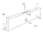
- FIG. 3 is a perspective view, partly exploded, of the pole and bracket of FIG. 2 ;
- FIG. 4 is a sectional illustration of the bracket
- FIG. 5A is an elevation of the pole-engaging face off the bracket
- FIG. 5B is an illustration of the bracket viewed from its underside
- FIG. 6 is an illustration of another embodiment of the invention.
- FIG. 7 is an illustration of another embodiment of the invention.
- FIG. 8A is an illustration of the another embodiment of bracket range to support a shelf at an incline
- FIG. 8B is a side elevation of the bracket of FIG. 8A secured to an upright pole
- FIG. 9 is an illustration of another variation of the invention.
- FIG. 10 is an illustration of a bracket configured for cantilevered mountings.
- FIGS. 1A and 1B show a shelving system 14 having a plurality of upright poles 12 and shelf brackets 10 attached to the poles 12 .
- Shelves 16 are supported, at their ends, by brackets 10 .
- the shelving system 14 may include one or more cabinets 18 that may be secured directly to the upright poles 12 .
- the lower ends of the poles 12 rest on the floor and their upper ends may be securely engaged with the ceiling or to the wall, as by way of a return arm 20 .
- the poles 12 may be of a type commercially available from Rangine Corporation of Needham, Mass., formed from extruded aluminum, and of generally rectangular or square cross-section.
- Each pole 12 may be considered as having a front face 12 f , a rear face 12 r and side faces 12 s .
- the side faces of the pole 12 s are, in a preferred embodiment, formed with longitudinally extending channels 20 that include longitudinally extending threads 22 adapted to be engaged with machine bolts or the like.
- the front and rear faces 12 f , 12 r of the pole 12 may include channels 24 designed to accept a cantilevered bracket of the type described in U.S. Pat. No. 3,865,337, although those are not a part of the present invention.
- a direction toward the front of the shelving system will be referred to as “forward” and a reverse direction (i.e., toward the wall) will be referred to as “rearward.”
- the side faces of poles that support brackets that cooperate to support the ends of a shelf are attached are referred to as facing inwardly.”
- FIGS. 2-5 illustrate one form of the bracket.
- the bracket 10 has an elongate rigid body and is generally L-shaped in cross-section ( FIG. 4 ), having an upright wall 26 and a flange 28 extending inwardly from the lower portion of the wall 26 .
- the flange is adapted to provide support for one end of a shelf 16 , the other end of the shelf being supported by a similar bracket, mounted on the next adjacent pole 12 .
- the bracket 10 may be extruded to include recessed scribe lines 30 , 32 , one of which 30 may serve to facilitate placement of holes 34 adapted to receive screws by which an end of a shelf can be secured to the flange and the other of which 32 may serve to locate a mounting aperture 36 on the bracket wall 26 .
- the web portion extends along the first axis a-a and along a second axis b-b oriented perpendicular to the first axis.
- the thickness of the web portion is measured along a third axis c-c, perpendicular to the first and the second axes.
- the shelf portion extends along the first and third axes.
- the web portion typically is flat and planar, as is the shelf portion, as illustrated.
- the first and third axes normally extend horizontally, and the second axis vertically, as shown.
- the upright wall 26 of the bracket 10 may be considered as having a pole-engaging face 38 and a shelf-engaging face 40 , the flange 28 projecting from the latter.
- the pole-engaging face is adapted to bear against a side face 12 s of the pole with the bracket 10 being secured to the pole by a fastener member, such as a threaded screw 42 adapted to engage securely the threaded channel 20 extending along a side face 12 s of the pole.
- a fastener member such as a threaded screw 42 adapted to engage securely the threaded channel 20 extending along a side face 12 s of the pole.
- the aperture 36 is positioned closer to the bottom of the wall 26 than the top so that when a shelf 16 is supported on the ledge 28 , the shelf will cover the screw head.
- the screw has a flat head and the aperture 36 is correspondingly countersunk to present a flush surface.
- Other types of suitable features may be used.
- the bracket 10 is provided with additional pole-engaging means that may take any of a number of forms.
- the bracket 10 is provided with a pair of ribs 44 , 46 extending from the pole-engaging side 38 of the bracket wall 26 , the ribs being spaced heightwise of each other.
- Each of the ribs is provided with a notch 48 that defines a pair of spaced shoulders 50 .
- the notch 48 and shoulders 50 are dimensioned so that when the pole-engaging face 38 is engaged with its associated side face 12 s of the pole 12 , a portion of the pole will be received within the notch 48 and will be embraced in close engagement by the shoulders 50 .
- a shelf bracket 10 securely fastened in this manner to the pole 12 , its position and orientation on the pole is fixed and rigid.
- the four pole-engaging shoulders 50 and the threaded fastener 42 cooperate to define four triangularly arranged points of engagement, with the fastener defining a common apex, between the pole and the bracket.
- the bracket 10 is a one-piece, unitary structure, preferably formed by extrusion, from a range of extrudable materials including metals such as aluminum. Other fabrication techniques, such as molding, also may be employed.
- the bracket is secured to the pole by a threaded fastener, such as a machine screw.
- a threaded fastener such as a machine screw.
- the main wall of the bracket includes an aperture to receive the machine screw.
- FIG. 6 illustrates another embodiment in which the arrangement for guiding, orienting and retaining the bracket relative to the pole is defined by surfaces of a plurality of pins 52 or other projections protruding from the pole-engaging face of the bracket.
- the ribs 44 , 46 may be omitted.
- the pins 52 may be press-fitted or otherwise secured to the pole-engaging face 38 of the bracket.
- the arrangement shown in FIG. 6 may be modified to include only a single pair of pins 52 adapted to engage the front and rear faces of the pole.
- the pins 52 should be aligned with each other to define at least one isosceles triangle between the pins and the bolt.
- FIG. 7 illustrates a modified form of the bracket in which the lower rib is omitted.
- a single rib, at the upper region of the bracket is employed.
- FIGS. 8A and 8B illustrate a variation of the invention in which it is desired to mount a shelf 16 at an incline.
- the bracket 10 is formed with guiding surfaces, such as shoulders, pins or a channel defined by a notch, or otherwise, adapted to engage the pole so that the bracket is not perpendicular to the pole.
- brackets such as that illustrated in FIGS. 3 and 4 may be modified to provide the shoulders 54 to align along parallel lines that lie at an angle other than perpendicular to the longitudinal axis of the bracket.
- the shoulders or channel wall or pins or the like
- the relationship between the fastening screw and the screws still defines one or more triangles.
- FIG. 9 shows a further embodiment of the invention in which the bracket wall 26 A is of increased thickness sufficient to enable a channel 56 to be formed along the full height of the wall 26 A on the pole-engaging face 38 of the bracket.
- the width of the channel is dimensioned with respect to the post to receive the post in snug engagement sufficiently to prevent relative rotation of the bracket with respect to the pole when the two are secured together.
- the channel includes sidewalls 58 that embrace the front and rear faces of the pole to prevent relative rotation.
- FIG. 10 illustrates a modified embodiment in which the guide surfaces (e.g., shoulders, pins) are located closer to one end of the bracket than to the other. This enables a bracket to be mounted in a cantilevered fashion.
- the guide surfaces e.g., shoulders, pins
Landscapes
- Assembled Shelves (AREA)
Abstract
Description
Claims (15)
Priority Applications (1)
| Application Number | Priority Date | Filing Date | Title |
|---|---|---|---|
| US11/544,226 US7506852B1 (en) | 2006-10-06 | 2006-10-06 | Shelving support bracket |
Applications Claiming Priority (1)
| Application Number | Priority Date | Filing Date | Title |
|---|---|---|---|
| US11/544,226 US7506852B1 (en) | 2006-10-06 | 2006-10-06 | Shelving support bracket |
Publications (1)
| Publication Number | Publication Date |
|---|---|
| US7506852B1 true US7506852B1 (en) | 2009-03-24 |
Family
ID=40467348
Family Applications (1)
| Application Number | Title | Priority Date | Filing Date |
|---|---|---|---|
| US11/544,226 Active - Reinstated 2026-12-24 US7506852B1 (en) | 2006-10-06 | 2006-10-06 | Shelving support bracket |
Country Status (1)
| Country | Link |
|---|---|
| US (1) | US7506852B1 (en) |
Cited By (1)
| Publication number | Priority date | Publication date | Assignee | Title |
|---|---|---|---|---|
| US11547208B2 (en) * | 2018-04-13 | 2023-01-10 | Matthew G Bennett | Scoring or beverage station for a toss game |
Citations (9)
| Publication number | Priority date | Publication date | Assignee | Title |
|---|---|---|---|---|
| US625271A (en) * | 1899-05-16 | Adjustable washstand | ||
| US3343685A (en) * | 1965-10-23 | 1967-09-26 | Giambalvo Joseph | Modular shelf construction |
| US3771466A (en) * | 1971-12-27 | 1973-11-13 | Hirsh Co | Pole shelving |
| US3865337A (en) | 1971-12-27 | 1975-02-11 | Rangine Corp | Shelving arrangement or the like |
| US3920295A (en) * | 1973-12-20 | 1975-11-18 | Leonard A Speckin | Column mounted tool holder |
| US4730802A (en) * | 1987-08-26 | 1988-03-15 | Chatham Richard W | Detachable tray for stepladders |
| US4865283A (en) * | 1987-04-03 | 1989-09-12 | Parker Robert J | Merchandising display stand |
| US5996511A (en) * | 1998-02-09 | 1999-12-07 | Swoger; Gary J. | Tray device for attachment to a vertical pole |
| US6796249B1 (en) * | 2000-11-04 | 2004-09-28 | Minas N. Hiras | Window shelf |
-
2006
- 2006-10-06 US US11/544,226 patent/US7506852B1/en active Active - Reinstated
Patent Citations (9)
| Publication number | Priority date | Publication date | Assignee | Title |
|---|---|---|---|---|
| US625271A (en) * | 1899-05-16 | Adjustable washstand | ||
| US3343685A (en) * | 1965-10-23 | 1967-09-26 | Giambalvo Joseph | Modular shelf construction |
| US3771466A (en) * | 1971-12-27 | 1973-11-13 | Hirsh Co | Pole shelving |
| US3865337A (en) | 1971-12-27 | 1975-02-11 | Rangine Corp | Shelving arrangement or the like |
| US3920295A (en) * | 1973-12-20 | 1975-11-18 | Leonard A Speckin | Column mounted tool holder |
| US4865283A (en) * | 1987-04-03 | 1989-09-12 | Parker Robert J | Merchandising display stand |
| US4730802A (en) * | 1987-08-26 | 1988-03-15 | Chatham Richard W | Detachable tray for stepladders |
| US5996511A (en) * | 1998-02-09 | 1999-12-07 | Swoger; Gary J. | Tray device for attachment to a vertical pole |
| US6796249B1 (en) * | 2000-11-04 | 2004-09-28 | Minas N. Hiras | Window shelf |
Cited By (1)
| Publication number | Priority date | Publication date | Assignee | Title |
|---|---|---|---|---|
| US11547208B2 (en) * | 2018-04-13 | 2023-01-10 | Matthew G Bennett | Scoring or beverage station for a toss game |
Similar Documents
| Publication | Publication Date | Title |
|---|---|---|
| US12178334B2 (en) | Retail merchandise tray and display incorporating same | |
| US8297575B2 (en) | Shelf support bracket and wall standard | |
| US4666115A (en) | Plant hanger | |
| US6435461B1 (en) | Support rail assembly for office accessories | |
| EP2550803B1 (en) | Video screen mounting system | |
| US8844210B2 (en) | Upmount overhead brackets for office partition systems | |
| US11576486B2 (en) | Multidirectional wall mounted storage panel | |
| US20060108486A1 (en) | Apparatus for supporting an object on a wall | |
| US20100140202A1 (en) | Free Standing Shelving Unit | |
| US10393311B2 (en) | Support assembly | |
| US20080105812A1 (en) | Method and device for an adjustable hanger | |
| US7506852B1 (en) | Shelving support bracket | |
| GB2585747A (en) | Rack system, profile element and method for producing a profile element | |
| CN101340834A (en) | Shelf system comprising infinitely adjustable brackets in wall rails | |
| CN1758866A (en) | Display system | |
| US11186995B2 (en) | Handrail wall mount adapter | |
| US20070262220A1 (en) | Shelf support system | |
| JP4518972B2 (en) | Top plate support structure | |
| WO1994023613A1 (en) | Shelf support | |
| GB2340384A (en) | Fixing bracket | |
| EP1150595B1 (en) | Device for a holder | |
| US20110210090A1 (en) | Support stand | |
| EP2393304A1 (en) | Profiled beam to build a light weight solid cable management cabinet | |
| JP2519664Y2 (en) | Shelf receiving device | |
| WO1988006420A1 (en) | Improved bracket arrangement |
Legal Events
| Date | Code | Title | Description |
|---|---|---|---|
| AS | Assignment |
Owner name: EADS DEUTSCHLAND GMBH, GERMANY Free format text: ASSIGNMENT OF ASSIGNORS INTEREST;ASSIGNOR:JAENKER, PETER;REEL/FRAME:017536/0121 Effective date: 20050802 |
|
| AS | Assignment |
Owner name: RANGINE CORPORATION, MASSACHUSETTS Free format text: ASSIGNMENT OF ASSIGNORS INTEREST;ASSIGNORS:TOWFIGH, KEIVAN;GREENBERG, DAVID A.;REEL/FRAME:022230/0831 Effective date: 20090209 |
|
| REMI | Maintenance fee reminder mailed | ||
| FEPP | Fee payment procedure |
Free format text: PETITION RELATED TO MAINTENANCE FEES FILED (ORIGINAL EVENT CODE: PMFP); ENTITY STATUS OF PATENT OWNER: SMALL ENTITY |
|
| FEPP | Fee payment procedure |
Free format text: PETITION RELATED TO MAINTENANCE FEES GRANTED (ORIGINAL EVENT CODE: PMFG); ENTITY STATUS OF PATENT OWNER: SMALL ENTITY |
|
| LAPS | Lapse for failure to pay maintenance fees | ||
| REIN | Reinstatement after maintenance fee payment confirmed | ||
| FPAY | Fee payment |
Year of fee payment: 4 |
|
| FP | Lapsed due to failure to pay maintenance fee |
Effective date: 20130324 |
|
| PRDP | Patent reinstated due to the acceptance of a late maintenance fee |
Effective date: 20130618 |
|
| STCF | Information on status: patent grant |
Free format text: PATENTED CASE |
|
| STCF | Information on status: patent grant |
Free format text: PATENTED CASE |
|
| FPAY | Fee payment |
Year of fee payment: 8 |
|
| FEPP | Fee payment procedure |
Free format text: MAINTENANCE FEE REMINDER MAILED (ORIGINAL EVENT CODE: REM.); ENTITY STATUS OF PATENT OWNER: SMALL ENTITY |
|
| FEPP | Fee payment procedure |
Free format text: 11.5 YR SURCHARGE- LATE PMT W/IN 6 MO, SMALL ENTITY (ORIGINAL EVENT CODE: M2556); ENTITY STATUS OF PATENT OWNER: SMALL ENTITY |
|
| MAFP | Maintenance fee payment |
Free format text: PAYMENT OF MAINTENANCE FEE, 12TH YR, SMALL ENTITY (ORIGINAL EVENT CODE: M2553); ENTITY STATUS OF PATENT OWNER: SMALL ENTITY Year of fee payment: 12 |