US750140A - welsh - Google Patents
welsh Download PDFInfo
- Publication number
- US750140A US750140A US750140DA US750140A US 750140 A US750140 A US 750140A US 750140D A US750140D A US 750140DA US 750140 A US750140 A US 750140A
- Authority
- US
- United States
- Prior art keywords
- tower
- carriage
- carrier
- counterweight
- revoluble
- Prior art date
- Legal status (The legal status is an assumption and is not a legal conclusion. Google has not performed a legal analysis and makes no representation as to the accuracy of the status listed.)
- Expired - Lifetime
Links
- 238000010276 construction Methods 0.000 description 4
- 229910000746 Structural steel Inorganic materials 0.000 description 2
- 239000004020 conductor Substances 0.000 description 2
- 238000004873 anchoring Methods 0.000 description 1
- 230000005484 gravity Effects 0.000 description 1
- 230000002459 sustained effect Effects 0.000 description 1
Images

Classifications
-
- A—HUMAN NECESSITIES
- A63—SPORTS; GAMES; AMUSEMENTS
- A63G—MERRY-GO-ROUNDS; SWINGS; ROCKING-HORSES; CHUTES; SWITCHBACKS; SIMILAR DEVICES FOR PUBLIC AMUSEMENT
- A63G1/00—Roundabouts
- A63G1/44—Roundabouts with turntables moved up and down
Definitions
- ratus which from the nature of its parts mayA be appropriately designated as an aerial whirling tower; and the object that I have in view is to provide a simple and secure form of apparatus, wherein provision is made for carrying passenger-cars to a desired height above the ground and for moving said cars in a circular horizontal path during the elevation and lowering movements, whereby the cars travel in spiral paths and a good panoramic view of the locality is afforded to the passengers.
- Figure l is a side elevation, partly invertical section, of an amusement apparatus constructed in accordance with my invention.
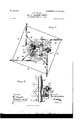
- Fig. 2 is a sectional plan view, on an enlarged scale, through the tower, the-vertically-traveling carriage, and the horizontally-rotating carrier
- Fig. 3 is a detail vertical sectional elevation showing one embodiment of means for supplying electrical energy to the'motor, adapted to rotate a car-carrier 'in ahorizontal plane
- Fig.l 4 is a diagrammatic view illustrating the arrangement of cables for operatively connecting the counterweight with the slidable carrier and a hauling-cable adapted to raise the slidable carrier by pulling down on the counterweight.
- a vertical tower A which is of metallic skeletonized construction and is erected on a suitable foundation B.
- the tower andthe foundation may be of any approved construction known to those skilled in the art, but, as
- the tower is square inv cross-section and built up of a series of and-fastened on the several sides of the structure. place by suitable braces 7 at the bottom por-
- the tower as a whole is anchored inf tion thereof and by the guy-cables 8, the lat- Vter extending from the ground to the top'por-v4
- tower is shown by Fig. 1 as having a series of radial arms 9, fastened in a suitable way to the tower at a point below the cap 10, the latter being surmounted by any suitable ornamentation or iiXture, such as the electric lamp 11. to the outer ends of the series of arms 9, and these arms are stayed to the ca'p portion of the tower by tension-rods 12.
- a carriage C On the tower is slidably mounted a carriage C, which surrounds said tower on the outside thereofY and is adapted for movement freely in a vertical direction thereon.
- rollers or their equivalents are mounted on the inner portion of the trackring, which constitutes a part of the verticallymovable carriage C, and these rollers are arranged to ride against the outer faces ofl the angle-iron tower-posts, whereby the carriage is limited to vertical movement on the tower,
- the carriage also contemplates the employment of a stay-ring 16, arranged in a horizontal position above the track-ring 13 and connected rigidly thereto by a series of bolt-rods 17, said bolts being attached in a suitable way to the rings 13 and 16, both of which encircle the tower and which are arranged in a parallel position.
- the carriage and the load sustained thereby are counterpoised by the employment of a counterweight D, arranged to travel within the limits of the tower, said counterweight being approximately square in cross-section and equipped with means whereby it may travel freely againstthe corner-posts 5 of the tower.
- This counterweight is shown as having a series of rollers 18, which are mounted in suitable supports at the corners of the weight, said rollers being arranged to turn freely on horizontal axes and disposed in radial positions relatively to the counterweight, so that the rollers-will ride against the inner faces of the cornerposts and in the angle formed by the meeting facesof saidposts. (See Fig. 2.) rIheemployment of the rollers arranged to ride against the posts in the manner described prevents the eounterweight from twisting or turning out of position within the tower, and this counterweight is adapted to move with minimum friction vertically within the tower and in an opposite direction to the travel of the carriage C with its load.
- the carriage is operatively connected with the counterweight by the employment of the series of cables 19, preferably four in number, said cables being' fastened at their lower ends to the counterweight in any approved wa as, for example, by the provision of an eye 2O at the center of said counterweight.
- the cables pass in upward directions and within the tower from the counterweight to and over guidesheaves 21, journalcd in the upper portion of the tower A, and said cables thence pass in downward directions from the sheaves to the carriage C, the lower ends of said cables being fastened in a suitable way to a part of the carriage as, for example, to the upper ring 16.
- a suitable hoisting-motor E and a hoisting-cable 22 for the purpose of raising the carriage and its load, and in the embodiment of the invention shown by the drawings this hoisting-cable 22 passes from a suitable drum of the hoisting-engine to and beneath a guidesheave 23, anchored at the base of the tower, whence said cable 22 passes upwardly within the tower and is fastened to the bottom portion of the counterweight D in a suitable way.
- the carriage is adapted to sustain a horizontal revoluble carrier, on which or from which is supported a series of passenger-cars.
- This revoluble carrier consists of inner rings 24 25 and a series of outwardly-extending arms 26, said parts being suitably connected and stayed.
- the member 24 of the revoluble carrier is fitted operatively to the track-ring 13 of the carriage, while the member 25 is disposed in like relation to the member 16 of said carriage, said carrier members 24 25 being united by stay rods or bolts 27.
- the base member 24 of the revoluble carrier is provided with a series of sockets 28, preferably four in number, and in these sockets are firmly secured the metallic arms 26 of said carrier, said arms extending tangentially from the periphery of the base member 24, as indicated more clearly by Fig. 2.
- the arms 26 are held firmly in place by the diagonal braces 29, and said arms are united in series by the stays 30, attached to the arms at or near the outer ends thereof.
- the revoluble carrier is mounted on the vertically-slidable carriage to move up and down therewith on the tower, and said carrier is also capable of rotation in a horizontal plane freely around the carriage. Any suitable mechanism may be employed for imparting the desired rotation to the carrier as it travels vertically with the slidable carriage; but in the drawings I have shown the apparatus as being equipped with electricallydriven means for rotating this carrier.
- An electric motor 31 of any suitable pattern is erected on an expanded or widened portion 32 of the base member 24, forming a part of the revoluble carrier, and the shaft of this motor is provided with a worm 32, which meshes with a worm-gear 33, the said gear being fast with a driving-shaft 33, the latter being provided with a gear-pinion 34, arranged to mesh with the teeth of an externally-geared circular rack 35, which is fastened solidly to the member 13 of the carriage.
- the electric motor and the gearing are mounted on the revoluble carrier to travel therewith, and the rotation of the motor-shaft operates the countershaft 33 to make the gear-pinion track around the circularrack 35.
- the current of electrical energy may be supplied n any suitable way to the electric motor; but, as shown by Figs. 2 and 3, the tower is equipped with a vertical grooved conductorbase 36, the latter being secured solidly to one side of the tower.
- a series of metallic conductorrails 37 In the grooves of this base 36 is provided a series of metallic conductorrails 37, which are engaged by a series of brushes 38, attached to the under side of the member 13, forming a part of the verticallymovable carriage.
- the base member 24 of the revoluble carrier is equipped with a series of circular conductor-plates 39, which are in- IOO IIO
- This construction and arrangement of conductors 37 39 and the brushes enables me to supply a current of electrical energyto the motor at all points in the vertical movement of the carriage and in the horizontal movement of the carrier, whereby the motor operates ly to propel the carrier in a horizontal path during its vertical travel with the carrier C.
- This carrier may be of any suitable or preferred construction; but it should be of such strength as to sustain a series of passengercars F, the latter being supported by the outer ends of the arms 26. Any suitable type of car may be employed, and I prefer to suspend the cars from said arms of the revoluble carrier.
- any suitable means may be employed for illuminating the tower and the cars, and in Fig. 2 the tower is shown as equipped with a vertical conductor-base 41, which may convey an electric current to the top lamp 11 and through suitable appliances to electric lamps in the cars F.
- the operation of my invention will be readily understood from the foregoing description, taken in connection with the drawings.
- the carriage C and its load exceed the weight of the counterweight D, and normally the loaded carriage has a tendency to travel downward on the tower toward the base thereof.
- the passengers may easily enter the car F when the apparatus is lowered, and when it is desired to raise the carriage the hoisting-motor E is set in motion to wind the vcable 22 on a suitable drum, thus pulling downwardly on the weight D, which in turn pulls on the cables 19, so as to raise the carriage C on the tower.
- the motor 3l is supplied with the current of electrical energy from the conductors 37, and the rotation of this motor operates to propel the carrier in a horizontal plane, whereby the carrier is capable of moving in a spiral path, owing to its movement with the carriage and the rotary tor during-the vertical travel.
- An amusement apparatus comprising a tower, a non-revoluble carriage limited to slidable movement on said tower, a carrier revoluble on said carriage and'movable vertically therewith, a .counterweight slidable in the tower'and connected operatively with said carriage, the aggregate weight of the carriage lowered position relative to the tower, a hauling-cable attached to the counterweight, and a suitable motor or engine for pulling on the cable and the counterweight to counteract the gravity of the carrier and carriage.
- An amusement apparatus comprising a tower having a series of posts forming external track-surfaces, a non-revoluble carriage slidable relatively to the tower, rollers mounted on the carriage to turn on horizontal axes and arranged to ride against the track-sur faces of the tower-posts, said rollers being grouped in pairs at each angle of the tower, and the rollers of each pair lying at right angles to one another and disposed to ride against separate track-faces of one towerpost, a revoluble carrier on said slidable carriage, mechanism for imparting vertical movement to the carriage, and means for rotating said carrier.
- An amusement apparatus comprising a tower having corner-posts of angular crosssectional form, a slidable and revoluble carrier arranged externally on the tower, a counterweight slidable inside of the tower, rollers mounted on the corner portions of the counterweight to rotate on horizontal axes and riding against track-faces afforded by the inner angular portions of the tower-posts, flexible connections between the carriage and said counterweight, and a hauling-cable attached to the counterweight.
- An amusement apparatus having a tower, a non-revoluble carriage slidable on said tower,
- a carrier supported revolubly on said carriage, an externally-toothed circular rack in Xed relation to Said sldable Carriage, a motor mounted on said carrier to travel therewith, and a counter-shaft geared to the motor-shaft and to the rack, whereby the carrier may be rotated around the Carriage.
Landscapes
- Jib Cranes (AREA)
Description
No. 750,140. PATENTED JAN.'19, 1904,.
N0 MODEL.
J. H. WELSH.
AERIAL WHIRLING TOWER.
. APPLICATION IILBD FEB. Z7, 1903.
2 SHEETS-SHEET 1.
@y ,gu A UUR/v5 ys.
THE Nonms #Frans cu. Puo-rauwe, wAsmNamN, uv v 4 0 9 1.. 9, l N.. A J D E T N E T A D..
E s L .E W E J. 0. 4. l, o 5, ,7 nu N AERIAL WHIRLING TOWER.
APPLICATION FILED PEB. 27, 1903.
2 SHEETS-SHEET 2.
N0 MODEL.
W/ T/VE SSE S.'
`A TTORNE YS.
Patented January 19, 1904,.
PATENT OFFICE.
JOHN H.v -WRLsH, or NRW YORK, N. Y.
AERIAL'WHIRLING TOWER.
l SPECIFIGATION forming part of Letters Patent No. 750,140, dated January 19, 1904. Application ied February 217, 1903.. serai No. 145,316. (No masi.)
ratus, which from the nature of its parts mayA be appropriately designated as an aerial whirling tower; and the object that I have in view is to provide a simple and secure form of apparatus, wherein provision is made for carrying passenger-cars to a desired height above the ground and for moving said cars in a circular horizontal path during the elevation and lowering movements, whereby the cars travel in spiral paths and a good panoramic view of the locality is afforded to the passengers.
Further objects and advantages of the in-V vention will appear in the course of the sub- Joined description, and the novelty will be de- `ined by the annexed drawings.
Reference is to be had to the accompanying drawings, forming a part Vof `this specication,
in Which similar characters of reference indicate corresponding parts in' all the figures.
Figure l is a side elevation, partly invertical section, of an amusement apparatus constructed in accordance with my invention;
Fig. 2 is a sectional plan view, on an enlarged scale, through the tower, the-vertically-traveling carriage, and the horizontally-rotating carrier, and Fig. 3 is a detail vertical sectional elevation showing one embodiment of means for supplying electrical energy to the'motor, adapted to rotate a car-carrier 'in ahorizontal plane. Fig.l 4 is a diagrammatic view illustrating the arrangement of cables for operatively connecting the counterweight with the slidable carrier and a hauling-cable adapted to raise the slidable carrier by pulling down on the counterweight.
In carrying my invention into practice I employ a vertical tower A, which is of metallic skeletonized construction and is erected on a suitable foundation B. The tower andthe foundation may be of any approved construction known to those skilled in the art, but, as
shown by Figs. 1 and 2, the tower is square inv cross-section and built up of a series of and-fastened on the several sides of the structure. place by suitable braces 7 at the bottom por- The tower as a whole is anchored inf tion thereof and by the guy-cables 8, the lat- Vter extending from the ground to the top'por-v4 This upper part of the` tion of the tower. tower is shown by Fig. 1 as having a series of radial arms 9, fastened in a suitable way to the tower at a point below the cap 10, the latter being surmounted by any suitable ornamentation or iiXture, such as the electric lamp 11. to the outer ends of the series of arms 9, and these arms are stayed to the ca'p portion of the tower by tension-rods 12.
On the tower is slidably mounted a carriage C, which surrounds said tower on the outside thereofY and is adapted for movement freely in a vertical direction thereon.
13, which is provided with inwardly-extending supports 14 in the form of lugs, that are integral with the ring 13, said lugs being disposed in pairs at the corners of' the tower. These supports 111 are equipped with pairs of rollers 15 15, one pair of which is disposed The anchoring guy-cables 8 are fastened This carriage C is shown in the -forrn of a track-ring at each corner of the tower, and said rollers are arranged, asshown by Fig. 2, for the axes to vlie at right angles to each other, whereby the rollers of each pair are adapted to travel on the faces of one angle-iron at the corner of the tower. It will be understood that four pairs of these rollers or their equivalents are mounted on the inner portion of the trackring, which constitutes a part of the verticallymovable carriage C, and these rollers are arranged to ride against the outer faces ofl the angle-iron tower-posts, whereby the carriage is limited to vertical movement on the tower,
and it is adapted to travel vertically thereon with minimum friction between the engaging surfaces. The carriage also contemplates the employment of a stay-ring 16, arranged in a horizontal position above the track-ring 13 and connected rigidly thereto by a series of bolt-rods 17, said bolts being attached in a suitable way to the rings 13 and 16, both of which encircle the tower and which are arranged in a parallel position. The carriage and the load sustained thereby are counterpoised by the employment of a counterweight D, arranged to travel within the limits of the tower, said counterweight being approximately square in cross-section and equipped with means whereby it may travel freely againstthe corner-posts 5 of the tower. This counterweight is shown as having a series of rollers 18, which are mounted in suitable supports at the corners of the weight, said rollers being arranged to turn freely on horizontal axes and disposed in radial positions relatively to the counterweight, so that the rollers-will ride against the inner faces of the cornerposts and in the angle formed by the meeting facesof saidposts. (See Fig. 2.) rIheemployment of the rollers arranged to ride against the posts in the manner described prevents the eounterweight from twisting or turning out of position within the tower, and this counterweight is adapted to move with minimum friction vertically within the tower and in an opposite direction to the travel of the carriage C with its load.
The carriage is operatively connected with the counterweight by the employment of the series of cables 19, preferably four in number, said cables being' fastened at their lower ends to the counterweight in any approved wa as, for example, by the provision of an eye 2O at the center of said counterweight. The cables pass in upward directions and within the tower from the counterweight to and over guidesheaves 21, journalcd in the upper portion of the tower A, and said cables thence pass in downward directions from the sheaves to the carriage C, the lower ends of said cables being fastened in a suitable way to a part of the carriage as, for example, to the upper ring 16.
The weight of the carriage and its load eX- ceeds the ponderosity of the counterweight D, and normally the carriage and the load rest at the bottom portion of the tower. I employ a suitable hoisting-motor E and a hoisting-cable 22 for the purpose of raising the carriage and its load, and in the embodiment of the invention shown by the drawings this hoisting-cable 22 passes from a suitable drum of the hoisting-engine to and beneath a guidesheave 23, anchored at the base of the tower, whence said cable 22 passes upwardly within the tower and is fastened to the bottom portion of the counterweight D in a suitable way.
The carriage is adapted to sustain a horizontal revoluble carrier, on which or from which is supported a series of passenger-cars. This revoluble carrier consists of inner rings 24 25 and a series of outwardly-extending arms 26, said parts being suitably connected and stayed. The member 24 of the revoluble carrier is fitted operatively to the track-ring 13 of the carriage, while the member 25 is disposed in like relation to the member 16 of said carriage, said carrier members 24 25 being united by stay rods or bolts 27. The base member 24 of the revoluble carrier is provided with a series of sockets 28, preferably four in number, and in these sockets are firmly secured the metallic arms 26 of said carrier, said arms extending tangentially from the periphery of the base member 24, as indicated more clearly by Fig. 2. The arms 26 are held firmly in place by the diagonal braces 29, and said arms are united in series by the stays 30, attached to the arms at or near the outer ends thereof.
The revoluble carrier is mounted on the vertically-slidable carriage to move up and down therewith on the tower, and said carrier is also capable of rotation in a horizontal plane freely around the carriage. Any suitable mechanism may be employed for imparting the desired rotation to the carrier as it travels vertically with the slidable carriage; but in the drawings I have shown the apparatus as being equipped with electricallydriven means for rotating this carrier. An electric motor 31 of any suitable pattern is erected on an expanded or widened portion 32 of the base member 24, forming a part of the revoluble carrier, and the shaft of this motor is provided with a worm 32, which meshes with a worm-gear 33, the said gear being fast with a driving-shaft 33, the latter being provided with a gear-pinion 34, arranged to mesh with the teeth of an externally-geared circular rack 35, which is fastened solidly to the member 13 of the carriage. It will be seen that the electric motor and the gearing are mounted on the revoluble carrier to travel therewith, and the rotation of the motor-shaft operates the countershaft 33 to make the gear-pinion track around the circularrack 35.
The current of electrical energy may be supplied n any suitable way to the electric motor; but, as shown by Figs. 2 and 3, the tower is equipped with a vertical grooved conductorbase 36, the latter being secured solidly to one side of the tower. In the grooves of this base 36 is provided a series of metallic conductorrails 37, which are engaged by a series of brushes 38, attached to the under side of the member 13, forming a part of the verticallymovable carriage. The base member 24 of the revoluble carrier is equipped with a series of circular conductor-plates 39, which are in- IOO IIO
dividually .engaged by the brushes 38 of the series, and to these conductor-plates `39 are electrically connected the wires 40 of the electric circuit, which includes the motor 3l. This construction and arrangement of conductors 37 39 and the brushes enables me to supply a current of electrical energyto the motor at all points in the vertical movement of the carriage and in the horizontal movement of the carrier, whereby the motor operates eficiently to propel the carrier in a horizontal path during its vertical travel with the carrier C. This carrier may be of any suitable or preferred construction; but it should be of such strength as to sustain a series of passengercars F, the latter being supported by the outer ends of the arms 26. Any suitable type of car may be employed, and I prefer to suspend the cars from said arms of the revoluble carrier.
Any suitable means may be employed for illuminating the tower and the cars, and in Fig. 2 the tower is shown as equipped with a vertical conductor-base 41, which may convey an electric current to the top lamp 11 and through suitable appliances to electric lamps in the cars F.
The operation of my invention will be readily understood from the foregoing description, taken in connection with the drawings. The carriage C and its load exceed the weight of the counterweight D, and normally the loaded carriage has a tendency to travel downward on the tower toward the base thereof. The passengers may easily enter the car F when the apparatus is lowered, and when it is desired to raise the carriage the hoisting-motor E is set in motion to wind the vcable 22 on a suitable drum, thus pulling downwardly on the weight D, which in turn pulls on the cables 19, so as to raise the carriage C on the tower. During the vertical travel of the ycarrierin an upward or downward direction the motor 3l is supplied with the current of electrical energy from the conductors 37, and the rotation of this motor operates to propel the carrier in a horizontal plane, whereby the carrier is capable of moving in a spiral path, owing to its movement with the carriage and the rotary tor during-the vertical travel.
movement that is imparted thereto by the mo- This mode of operation gives to the passengers a good panoramic view of the locality in which the appal vclaim as new and desire to secure by Letters Patent l. An amusement apparatus comprising a tower, a non-revoluble carriage limited to slidable movement on said tower, a carrier revoluble on said carriage and'movable vertically therewith, a .counterweight slidable in the tower'and connected operatively with said carriage, the aggregate weight of the carriage lowered position relative to the tower, a hauling-cable attached to the counterweight, and a suitable motor or engine for pulling on the cable and the counterweight to counteract the gravity of the carrier and carriage.
3. An amusement apparatus comprising a tower having a series of posts forming external track-surfaces, a non-revoluble carriage slidable relatively to the tower, rollers mounted on the carriage to turn on horizontal axes and arranged to ride against the track-sur faces of the tower-posts, said rollers being grouped in pairs at each angle of the tower, and the rollers of each pair lying at right angles to one another and disposed to ride against separate track-faces of one towerpost, a revoluble carrier on said slidable carriage, mechanism for imparting vertical movement to the carriage, and means for rotating said carrier. v
4:. An amusement apparatus comprising a tower having corner-posts of angular crosssectional form, a slidable and revoluble carrier arranged externally on the tower, a counterweight slidable inside of the tower, rollers mounted on the corner portions of the counterweight to rotate on horizontal axes and riding against track-faces afforded by the inner angular portions of the tower-posts, flexible connections between the carriage and said counterweight, and a hauling-cable attached to the counterweight.
5. In an amusement apparatus, the combination with a tower, of a non-revoluble carriage limited to slidable movement thereon, a revoluble carrier mounted on said carriage, a motor carried by one of said parts, gearing between the -motorshaft and the other part, conductor-rails supported by the tower, and current-collectors carried by the carriage and fritlztionally engaging with the conductorrai s.
6. An amusement apparatus having a tower, a non-revoluble carriage slidable on said tower,
IOO
IIO
a carrier supported revolubly on said carriage, an externally-toothed circular rack in Xed relation to Said sldable Carriage, a motor mounted on said carrier to travel therewith, and a counter-shaft geared to the motor-shaft and to the rack, whereby the carrier may be rotated around the Carriage.
In testimony whereof I have signed my name to this specification in the presence of two subscribing witnesses.
JOHN H. WELSH.
Witnesses: e
JNO. M. RITTER, H. F. BERNHARD.
Publications (1)
| Publication Number | Publication Date |
|---|---|
| US750140A true US750140A (en) | 1904-01-19 |
Family
ID=2818633
Family Applications (1)
| Application Number | Title | Priority Date | Filing Date |
|---|---|---|---|
| US750140D Expired - Lifetime US750140A (en) | welsh |
Country Status (1)
| Country | Link |
|---|---|
| US (1) | US750140A (en) |
Cited By (2)
| Publication number | Priority date | Publication date | Assignee | Title |
|---|---|---|---|---|
| US4712652A (en) * | 1985-03-22 | 1987-12-15 | Von Roll Ag. | Elevator for transporting people and goods with an annular travelling cabin |
| US5570546A (en) * | 1995-07-31 | 1996-11-05 | American High Mast Systems, Inc. | System for raising and lowering communications equipment |
-
0
- US US750140D patent/US750140A/en not_active Expired - Lifetime
Cited By (2)
| Publication number | Priority date | Publication date | Assignee | Title |
|---|---|---|---|---|
| US4712652A (en) * | 1985-03-22 | 1987-12-15 | Von Roll Ag. | Elevator for transporting people and goods with an annular travelling cabin |
| US5570546A (en) * | 1995-07-31 | 1996-11-05 | American High Mast Systems, Inc. | System for raising and lowering communications equipment |
Similar Documents
| Publication | Publication Date | Title |
|---|---|---|
| RU2607972C1 (en) | Racetrack tower | |
| US3633904A (en) | Rotary elevator observation tower | |
| US1124950A (en) | Roundabout. | |
| ES2961206T3 (en) | Systems and methods of attractions with scenic compartments | |
| US750140A (en) | welsh | |
| US2128492A (en) | Observation tower | |
| US1347968A (en) | Spiral-glide amusement device | |
| US1342828A (en) | Extensible mast | |
| US788707A (en) | Light-tower. | |
| US1023897A (en) | Aeroplane-roundabout. | |
| US730521A (en) | Pleasure-tower. | |
| US723759A (en) | Bathing-machine. | |
| US611682A (en) | engel | |
| US1263303A (en) | Portable elevator. | |
| US525031A (en) | Observation-tower | |
| US1008886A (en) | Theater and stage construction. | |
| US573577A (en) | Carousel | |
| US821409A (en) | Amusement apparatus. | |
| US1128466A (en) | Amusement device. | |
| US468792A (en) | critchlow | |
| US2255013A (en) | Amusement apparatus | |
| US865584A (en) | Portable amusement apparatus. | |
| US297332A (en) | Electric-light tower | |
| US750717A (en) | Rotary pleasure-tower | |
| US1207914A (en) | Amusement apparatus. |