US7494308B2 - Air tank fixing structure for commercial vehicles - Google Patents
Air tank fixing structure for commercial vehicles Download PDFInfo
- Publication number
- US7494308B2 US7494308B2 US11/298,646 US29864605A US7494308B2 US 7494308 B2 US7494308 B2 US 7494308B2 US 29864605 A US29864605 A US 29864605A US 7494308 B2 US7494308 B2 US 7494308B2
- Authority
- US
- United States
- Prior art keywords
- air tank
- fixing
- vehicle
- air
- fixing member
- Prior art date
- Legal status (The legal status is an assumption and is not a legal conclusion. Google has not performed a legal analysis and makes no representation as to the accuracy of the status listed.)
- Active, expires
Links
Images


Classifications
-
- B—PERFORMING OPERATIONS; TRANSPORTING
- B60—VEHICLES IN GENERAL
- B60T—VEHICLE BRAKE CONTROL SYSTEMS OR PARTS THEREOF; BRAKE CONTROL SYSTEMS OR PARTS THEREOF, IN GENERAL; ARRANGEMENT OF BRAKING ELEMENTS ON VEHICLES IN GENERAL; PORTABLE DEVICES FOR PREVENTING UNWANTED MOVEMENT OF VEHICLES; VEHICLE MODIFICATIONS TO FACILITATE COOLING OF BRAKES
- B60T13/00—Transmitting braking action from initiating means to ultimate brake actuator with power assistance or drive; Brake systems incorporating such transmitting means, e.g. air-pressure brake systems
- B60T13/10—Transmitting braking action from initiating means to ultimate brake actuator with power assistance or drive; Brake systems incorporating such transmitting means, e.g. air-pressure brake systems with fluid assistance, drive, or release
- B60T13/24—Transmitting braking action from initiating means to ultimate brake actuator with power assistance or drive; Brake systems incorporating such transmitting means, e.g. air-pressure brake systems with fluid assistance, drive, or release the fluid being gaseous
-
- B—PERFORMING OPERATIONS; TRANSPORTING
- B60—VEHICLES IN GENERAL
- B60T—VEHICLE BRAKE CONTROL SYSTEMS OR PARTS THEREOF; BRAKE CONTROL SYSTEMS OR PARTS THEREOF, IN GENERAL; ARRANGEMENT OF BRAKING ELEMENTS ON VEHICLES IN GENERAL; PORTABLE DEVICES FOR PREVENTING UNWANTED MOVEMENT OF VEHICLES; VEHICLE MODIFICATIONS TO FACILITATE COOLING OF BRAKES
- B60T17/00—Component parts, details, or accessories of power brake systems not covered by groups B60T8/00, B60T13/00 or B60T15/00, or presenting other characteristic features
- B60T17/06—Applications or arrangements of reservoirs
-
- B—PERFORMING OPERATIONS; TRANSPORTING
- B62—LAND VEHICLES FOR TRAVELLING OTHERWISE THAN ON RAILS
- B62D—MOTOR VEHICLES; TRAILERS
- B62D61/00—Motor vehicles or trailers, characterised by the arrangement or number of wheels, not otherwise provided for, e.g. four wheels in diamond pattern
- B62D61/12—Motor vehicles or trailers, characterised by the arrangement or number of wheels, not otherwise provided for, e.g. four wheels in diamond pattern with variable number of ground engaging wheels, e.g. with some wheels arranged higher than others, or with retractable wheels
Definitions
- the present invention relates generally to an air tank fixing structure for commercial vehicles, and more particularly, to an air tank fixing structure for commercial vehicles capable of mounting air tanks, which are used for supplying hydraulic pressure for activating brake system and air suspension of the vehicle, to the vehicle in common.
- a commercial vehicle like a truck has at least one air tank installed to its frame, such as a cross member, in order to supply air, wherein the air is required to activate a brake system for braking the vehicle or an air suspension for lessening down impact or vibration generated from a suspension system when a vehicle is in motion.
- an air tank fixing structure for vehicles capable of integrally fixing air tanks, which are suitably used for supplying air for activating a brake system and/or air suspension of the vehicle.
- an air tank fixing structure for a vehicle which may include a first air tank fixing member fixed onto a body frame at one side thereof, and formed with at least one first fixing element in which at least one air tank for the commercial vehicle is fixed at the other side; and a second air tank fixing member formed with at least one second fixing element and fixed to the air tank.
- an air tank fixing structure for commercial vehicles.
- the air tank fixing structure preferably includes a first air tank fixing member fixed onto a body frame at one side thereof and fixed with at least one air tank for the vehicle at the other side, and a second air tank fixing member formed and installed on the air tank after the air tank is rested on the first air tank fixing member.
- the air tanks and the respective fixing members are fixed by a fastening bolt preferably of a U-shape so as to allow of maintenance of a rested state of the air tanks on the fixing members.
- the air tanks are suitably integrally fixed at the same place of the frame of the vehicle without being distributed at many places of the commercial vehicle, such as a truck.
- the invention also includes vehicles particularly commercial vehicles such as trucks and the like that comprise an air tank fixing structure as described herein.
- vehicle or “vehicular” or other similar terms as used herein is inclusive of motor vehicles in general such as passenger automobiles including sports utility vehicles (SUV), buses, trucks, various commercial vehicles, and the like.
- preferred vehicles are commercial vehicles such as trucks and the like which may have air brakes or air suspension, or other vehicles that may have air brakes and/or air suspension systems
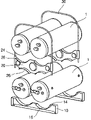
- FIG. 1 is an exploded perspective view showing one embodiment of the air tank fixing structure for commercial vehicles according to the present invention.
- FIG. 2 is a perspective view showing an assembled state of one embodiment of the air tank fixing structure for commercial vehicles according to the present invention.
- an air tank fixing structure for a vehicle may include a first air tank fixing member fixed onto a body frame at one side thereof, and formed with at least one first fixing element in which at least one air tank for the vehicle is fixed at the other side; and a second air tank fixing member formed with at least one second fixing element and fixed to the air tank.
- the air tank fixing structure suitably may further comprise a fastening element that can hold the air tank and the first and second air tank fixing members.
- Suitable fastening elements include e.g. bolt elements.
- Preferred first and second fixing elements may have a variety of configurations including recesses.
- FIG. 1 is an exploded perspective view showing one embodiment of the air tank fixing structure for commercial vehicles according to the present invention. The embodiment of the present invention will be described below with reference to this drawing.
- a first air tank fixing bracket 10 is installed to the frame of a vehicle so as to enable both ends of at least one air tank to be located at a position where the air tank is fixed.
- the first air tank fixing bracket 10 preferably has a linear portion brought into contact with the frame, and at least one first fixing recess 16 fixing the air tank 1 on the side opposite to the linear portion.
- an outer surface of the air tank 1 has the same curvature as the first fixing recess 16 .
- a second air tank fixing bracket 20 is disposed on the air tank 1 .
- the second air tank fixing bracket 20 is formed with second fixing recesses 26 on both sides thereof, wherein the air tank 1 is fixed in each of the second fixing recesses 26 .
- the second fixing recesses 26 of the second air tank fixing bracket 20 are preferably formed in axial symmetry.
- the air tank 1 is additionally suitably disposed in the second fixing recess 26 formed on the other side of the second air tank fixing bracket 20 .
- first and second air tank fixing brackets 10 and 20 and the air tanks 1 are suitably fixed e.g. using fastening bolts 30 .
- one or more of the fastening bolts 30 is formed in a U-shape.
- both ends of each fastening bolt 30 pass through first and second bolt holes 14 and 24 which are formed on both ends of each of the first and second air tank fixing brackets 10 and 20 , and then are fixed using nuts on the side of the first air tank fixing bracket 10 .
- a width of each fastening bolt 30 should be preferably formed so as to be at least twice as large as the diameter of each air tank 1 .
- each fastening bolt 30 is formed to have the same curvature as that of the outer surface of each air tank 1 , and thereby firm fixation is achieved through dose contact between the fastening bolts 30 and the air tanks 1 .
- the plurality of air tanks used in the commercial vehicle can be fixed to the same place, as shown in FIG. 2 .
- the air tanks which supply the air used to activate the air brake or air suspension of a vehicle, can be integrally fixed on one side of the vehicle.
Abstract
Description
Claims (11)
Applications Claiming Priority (2)
| Application Number | Priority Date | Filing Date | Title |
|---|---|---|---|
| KR1020050104030A KR100657687B1 (en) | 2005-11-01 | 2005-11-01 | A air tank fixing structure for commercial use vehicle |
| KR2005-0104030 | 2005-11-01 |
Publications (2)
| Publication Number | Publication Date |
|---|---|
| US20070098515A1 US20070098515A1 (en) | 2007-05-03 |
| US7494308B2 true US7494308B2 (en) | 2009-02-24 |
Family
ID=37733350
Family Applications (1)
| Application Number | Title | Priority Date | Filing Date |
|---|---|---|---|
| US11/298,646 Active 2026-08-25 US7494308B2 (en) | 2005-11-01 | 2005-12-08 | Air tank fixing structure for commercial vehicles |
Country Status (3)
| Country | Link |
|---|---|
| US (1) | US7494308B2 (en) |
| KR (1) | KR100657687B1 (en) |
| DE (1) | DE102005059278A1 (en) |
Cited By (10)
| Publication number | Priority date | Publication date | Assignee | Title |
|---|---|---|---|---|
| US20080164251A1 (en) * | 2007-01-08 | 2008-07-10 | Ncf Industries, Inc. | Intermodal container for transporting natural gas |
| US20080230427A1 (en) * | 2007-03-22 | 2008-09-25 | Muth James T | Keg Stacking Device |
| US20080283436A1 (en) * | 2007-04-06 | 2008-11-20 | Luca Tagliaferri | Supporting structure for storing and handling so-called "barriques" |
| US20100263967A1 (en) * | 2009-04-20 | 2010-10-21 | Michael P. Ziaylek | Portable tank lifting and handling apparatus |
| US8801005B1 (en) * | 2011-10-04 | 2014-08-12 | DST Output West, LLC | Rolled material transfer cart |
| US20170071336A1 (en) * | 2014-10-22 | 2017-03-16 | Dennis Brian Wilhelmsen | Nesting transportable wine barrel rack |
| US20180044101A1 (en) * | 2016-08-09 | 2018-02-15 | Hendrickson Usa, L.L.C. | Bracket system |
| US20180283610A1 (en) * | 2017-03-31 | 2018-10-04 | Other Lab, Llc | Tank enclosure and tank mount system and method |
| US10821657B2 (en) | 2015-12-02 | 2020-11-03 | Other Lab, Llc | Systems and methods for liner braiding and resin application |
| US10851925B2 (en) | 2016-10-24 | 2020-12-01 | Other Lab, Llc | Fittings for compressed gas storage vessels |
Families Citing this family (1)
| Publication number | Priority date | Publication date | Assignee | Title |
|---|---|---|---|---|
| CN102398580B (en) * | 2010-09-17 | 2014-05-14 | 陈言平 | Air-pressure braking system |
Citations (28)
| Publication number | Priority date | Publication date | Assignee | Title |
|---|---|---|---|---|
| US3019916A (en) * | 1958-05-09 | 1962-02-06 | Republic Steel Corp | Portable drum rack |
| US3091348A (en) * | 1960-11-14 | 1963-05-28 | Reynolds Metals Co | Roll stacking device |
| US3430981A (en) * | 1966-06-25 | 1969-03-04 | Michele Tarantola | System for the safe anchoring of bombs or containers to a conveying means |
| US3476260A (en) * | 1967-12-05 | 1969-11-04 | Jarke Corp | Storage rack for cylindrical containers |
| US4175666A (en) * | 1978-04-03 | 1979-11-27 | Kleen-Rite, Inc. | Tank support assemblies |
| USD256346S (en) * | 1978-08-21 | 1980-08-12 | Annis James M | Beer keg pallet |
| US4431107A (en) * | 1982-01-06 | 1984-02-14 | Agri-Fab Industries, Incorporated | Modular rack array |
| US4488649A (en) * | 1981-10-27 | 1984-12-18 | Larry D. Watts | Rack for plural cylindrical objects |
| US4506796A (en) * | 1983-03-02 | 1985-03-26 | Equipment Company Of America | Drum stacking rack |
| JPS60259519A (en) | 1984-06-01 | 1985-12-21 | Nippon Denso Co Ltd | Ventilating device for vehicle |
| JPS61135817A (en) | 1984-12-05 | 1986-06-23 | Nippon Denso Co Ltd | Air conditioner for vehicles |
| JPS6374716A (en) | 1986-09-18 | 1988-04-05 | Matsushita Electric Ind Co Ltd | On vehicle cooler/warmer |
| EP0393437A1 (en) | 1989-04-10 | 1990-10-24 | FIAT AUTO S.p.A. | Vehicle featuring an auxiliary solar cell electrical system, particularly for powering the air conditioning system of a stationary vehicle |
| US5040933A (en) * | 1990-05-08 | 1991-08-20 | Union Carbide Industrial Gases Technology Corporation | Trailer for cylindrical container modules |
| US5123547A (en) * | 1989-08-26 | 1992-06-23 | Drilltec Patents & Technologies Co., Inc. | Equipment for storing and shipping pipes |
| JPH08188031A (en) | 1995-01-06 | 1996-07-23 | Mitsubishi Heavy Ind Ltd | Vehicular air-conditioning system |
| US5735412A (en) * | 1996-05-22 | 1998-04-07 | Sheckells; Amuel E. | Self-griping rack and method for stacking articles with rack |
| JPH11105704A (en) | 1997-10-06 | 1999-04-20 | Hino Motors Ltd | Air tank fixing structure of vehicle |
| KR19990030632A (en) | 1997-10-02 | 1999-05-06 | 윤원석 | Vehicle indoor temperature control method using solar cell |
| US5984119A (en) * | 1998-01-06 | 1999-11-16 | Uhl; Kenneth T. | Back system for storing and transporting cylindrical containers |
| KR20000013223A (en) | 1998-08-06 | 2000-03-06 | 윤덕용 | Initial cooling device for vehicle |
| JP2000118232A (en) | 1998-10-09 | 2000-04-25 | Mitsuro Ito | Parking/stopping time and engine driving time car air conditioner using solar battery |
| JP2001018789A (en) | 1999-07-05 | 2001-01-23 | Nissan Diesel Motor Co Ltd | Mounting device for air reservoir tank |
| US6224024B1 (en) * | 1998-06-10 | 2001-05-01 | Kenneth H. Fritz | Portable retention apparatus for cylindrical objects |
| KR20020057600A (en) | 2001-01-02 | 2002-07-12 | 신영주 | System assistance a cold room and heating of vehicle in a parking/stoppage and their controlling method |
| US6637607B2 (en) * | 2000-09-22 | 2003-10-28 | Tonnellerie Baron | Rack for supporting circularly symmetrical containers |
| JP2004291680A (en) | 2003-03-25 | 2004-10-21 | Mazda Motor Corp | Vehicular air-conditioning system |
| US7195257B2 (en) * | 2004-12-21 | 2007-03-27 | Magline, Inc | Cargo cart system incorporating a portable container cradle |
Family Cites Families (6)
| Publication number | Priority date | Publication date | Assignee | Title |
|---|---|---|---|---|
| FR2188574A5 (en) * | 1972-06-06 | 1974-01-18 | Westinghouse Freins & Signaux | |
| IT223222Z2 (en) * | 1991-07-12 | 1995-06-13 | Iveco Fiat | MODULAR SUPPORT FOR COMPRESSED AIR TANKS INSTALLED ON INDUSTRIAL VEHICLES. |
| US5279317A (en) | 1993-02-26 | 1994-01-18 | Bowman Michael D | Endoscopic cannulated instrument flushing apparatus for forcing a cleaning solution through an endoscopic cannulated instrument for removal of gross debris |
| MY125147A (en) * | 1998-10-27 | 2006-07-31 | Univ Johns Hopkins | Compressed gas manifold |
| JP4686911B2 (en) | 2001-06-15 | 2011-05-25 | トヨタ自動車株式会社 | High pressure tank assembly for vehicles |
| KR100416942B1 (en) * | 2001-09-26 | 2004-01-31 | 주식회사 에어젠 | System for compressing fluid |
-
2005
- 2005-11-01 KR KR1020050104030A patent/KR100657687B1/en active IP Right Grant
- 2005-12-08 US US11/298,646 patent/US7494308B2/en active Active
- 2005-12-12 DE DE102005059278A patent/DE102005059278A1/en not_active Ceased
Patent Citations (28)
| Publication number | Priority date | Publication date | Assignee | Title |
|---|---|---|---|---|
| US3019916A (en) * | 1958-05-09 | 1962-02-06 | Republic Steel Corp | Portable drum rack |
| US3091348A (en) * | 1960-11-14 | 1963-05-28 | Reynolds Metals Co | Roll stacking device |
| US3430981A (en) * | 1966-06-25 | 1969-03-04 | Michele Tarantola | System for the safe anchoring of bombs or containers to a conveying means |
| US3476260A (en) * | 1967-12-05 | 1969-11-04 | Jarke Corp | Storage rack for cylindrical containers |
| US4175666A (en) * | 1978-04-03 | 1979-11-27 | Kleen-Rite, Inc. | Tank support assemblies |
| USD256346S (en) * | 1978-08-21 | 1980-08-12 | Annis James M | Beer keg pallet |
| US4488649A (en) * | 1981-10-27 | 1984-12-18 | Larry D. Watts | Rack for plural cylindrical objects |
| US4431107A (en) * | 1982-01-06 | 1984-02-14 | Agri-Fab Industries, Incorporated | Modular rack array |
| US4506796A (en) * | 1983-03-02 | 1985-03-26 | Equipment Company Of America | Drum stacking rack |
| JPS60259519A (en) | 1984-06-01 | 1985-12-21 | Nippon Denso Co Ltd | Ventilating device for vehicle |
| JPS61135817A (en) | 1984-12-05 | 1986-06-23 | Nippon Denso Co Ltd | Air conditioner for vehicles |
| JPS6374716A (en) | 1986-09-18 | 1988-04-05 | Matsushita Electric Ind Co Ltd | On vehicle cooler/warmer |
| EP0393437A1 (en) | 1989-04-10 | 1990-10-24 | FIAT AUTO S.p.A. | Vehicle featuring an auxiliary solar cell electrical system, particularly for powering the air conditioning system of a stationary vehicle |
| US5123547A (en) * | 1989-08-26 | 1992-06-23 | Drilltec Patents & Technologies Co., Inc. | Equipment for storing and shipping pipes |
| US5040933A (en) * | 1990-05-08 | 1991-08-20 | Union Carbide Industrial Gases Technology Corporation | Trailer for cylindrical container modules |
| JPH08188031A (en) | 1995-01-06 | 1996-07-23 | Mitsubishi Heavy Ind Ltd | Vehicular air-conditioning system |
| US5735412A (en) * | 1996-05-22 | 1998-04-07 | Sheckells; Amuel E. | Self-griping rack and method for stacking articles with rack |
| KR19990030632A (en) | 1997-10-02 | 1999-05-06 | 윤원석 | Vehicle indoor temperature control method using solar cell |
| JPH11105704A (en) | 1997-10-06 | 1999-04-20 | Hino Motors Ltd | Air tank fixing structure of vehicle |
| US5984119A (en) * | 1998-01-06 | 1999-11-16 | Uhl; Kenneth T. | Back system for storing and transporting cylindrical containers |
| US6224024B1 (en) * | 1998-06-10 | 2001-05-01 | Kenneth H. Fritz | Portable retention apparatus for cylindrical objects |
| KR20000013223A (en) | 1998-08-06 | 2000-03-06 | 윤덕용 | Initial cooling device for vehicle |
| JP2000118232A (en) | 1998-10-09 | 2000-04-25 | Mitsuro Ito | Parking/stopping time and engine driving time car air conditioner using solar battery |
| JP2001018789A (en) | 1999-07-05 | 2001-01-23 | Nissan Diesel Motor Co Ltd | Mounting device for air reservoir tank |
| US6637607B2 (en) * | 2000-09-22 | 2003-10-28 | Tonnellerie Baron | Rack for supporting circularly symmetrical containers |
| KR20020057600A (en) | 2001-01-02 | 2002-07-12 | 신영주 | System assistance a cold room and heating of vehicle in a parking/stoppage and their controlling method |
| JP2004291680A (en) | 2003-03-25 | 2004-10-21 | Mazda Motor Corp | Vehicular air-conditioning system |
| US7195257B2 (en) * | 2004-12-21 | 2007-03-27 | Magline, Inc | Cargo cart system incorporating a portable container cradle |
Cited By (16)
| Publication number | Priority date | Publication date | Assignee | Title |
|---|---|---|---|---|
| US20080164251A1 (en) * | 2007-01-08 | 2008-07-10 | Ncf Industries, Inc. | Intermodal container for transporting natural gas |
| US8146761B2 (en) * | 2007-01-08 | 2012-04-03 | Ncf Industries, Inc. | Intermodal container for transporting natural gas |
| US20080230427A1 (en) * | 2007-03-22 | 2008-09-25 | Muth James T | Keg Stacking Device |
| US7850019B2 (en) * | 2007-03-22 | 2010-12-14 | Muth James T | Keg stacking device |
| US20080283436A1 (en) * | 2007-04-06 | 2008-11-20 | Luca Tagliaferri | Supporting structure for storing and handling so-called "barriques" |
| US7841471B2 (en) * | 2007-04-06 | 2010-11-30 | Marchesi Antinori S.R.L. | Supporting structure for storing and handling so-called “barriques” |
| US20100263967A1 (en) * | 2009-04-20 | 2010-10-21 | Michael P. Ziaylek | Portable tank lifting and handling apparatus |
| US8382419B2 (en) | 2009-04-20 | 2013-02-26 | Michael P. Ziaylek | Portable tank lifting and handling apparatus |
| US8801005B1 (en) * | 2011-10-04 | 2014-08-12 | DST Output West, LLC | Rolled material transfer cart |
| US20170071336A1 (en) * | 2014-10-22 | 2017-03-16 | Dennis Brian Wilhelmsen | Nesting transportable wine barrel rack |
| US10219621B2 (en) * | 2014-10-22 | 2019-03-05 | Wilhelmsen Industries, Llc | Nesting transportable wine barrel rack |
| US10821657B2 (en) | 2015-12-02 | 2020-11-03 | Other Lab, Llc | Systems and methods for liner braiding and resin application |
| US11000988B2 (en) | 2015-12-02 | 2021-05-11 | Other Lab, Llc | Systems and methods for liner braiding and resin application |
| US20180044101A1 (en) * | 2016-08-09 | 2018-02-15 | Hendrickson Usa, L.L.C. | Bracket system |
| US10851925B2 (en) | 2016-10-24 | 2020-12-01 | Other Lab, Llc | Fittings for compressed gas storage vessels |
| US20180283610A1 (en) * | 2017-03-31 | 2018-10-04 | Other Lab, Llc | Tank enclosure and tank mount system and method |
Also Published As
| Publication number | Publication date |
|---|---|
| KR100657687B1 (en) | 2006-12-14 |
| US20070098515A1 (en) | 2007-05-03 |
| DE102005059278A1 (en) | 2007-05-03 |
Similar Documents
| Publication | Publication Date | Title |
|---|---|---|
| US7494308B2 (en) | Air tank fixing structure for commercial vehicles | |
| US20020190572A1 (en) | Support structure and method for supporting a hydraulic unit of a brake system on a vehicle body, and hydraulic unit arrangement for a vehicle brake system | |
| KR20170063594A (en) | Adjustable chassis for a motor vehicle | |
| US20050146109A1 (en) | Golf car suspension | |
| KR101316827B1 (en) | Roll rod mounting device for vehicle | |
| US6585068B2 (en) | Front vehicle body construction | |
| US7637514B2 (en) | Mounting structure of a rear suspension cross member of a vehicle | |
| JP2004216960A (en) | Mounting structure of abs actuator | |
| US6932410B2 (en) | Instrument-panel mounting system | |
| US6820884B2 (en) | Integrated axle adaptor and spring seat for a vehicle suspension system | |
| US8641128B2 (en) | Vehicle floor assembly with insert | |
| JPH1016822A (en) | Energy absorbing structure for body side section of automobile | |
| US9387886B2 (en) | Fasteners integrated into a vehicle frame | |
| JP2001233187A (en) | Brake pedal device for vehicle | |
| JP2000304192A (en) | Driving unit | |
| JP2003011680A (en) | Supporting structure for radiator | |
| US20120279041A1 (en) | Side step bar mounting system for trucks | |
| CN212073996U (en) | Automobile ABS unit installing support and car | |
| EP1544084B1 (en) | Support structure for a dashboard of a vehicle | |
| KR970046838A (en) | Structure of engine mounting bracket for automobile | |
| JPH07237502A (en) | Step for getting on/off from vehicle | |
| JPH07137523A (en) | Stabilizer bar mounting structure for automobile | |
| JP3352589B2 (en) | Car body structure | |
| JP2016098861A (en) | Cab mount | |
| US9701342B2 (en) | Vehicle suspension system, suspension mount assembly and method of mounting a subframe to a frame |
Legal Events
| Date | Code | Title | Description |
|---|---|---|---|
| AS | Assignment |
Owner name: HYUNDAI MOTOR COMPANY, KOREA, REPUBLIC OF Free format text: ASSIGNMENT OF ASSIGNORS INTEREST;ASSIGNOR:CHUN, CHONG C.;REEL/FRAME:017365/0699 Effective date: 20060110 |
|
| FEPP | Fee payment procedure |
Free format text: PAYOR NUMBER ASSIGNED (ORIGINAL EVENT CODE: ASPN); ENTITY STATUS OF PATENT OWNER: LARGE ENTITY |
|
| STCF | Information on status: patent grant |
Free format text: PATENTED CASE |
|
| FEPP | Fee payment procedure |
Free format text: PAYER NUMBER DE-ASSIGNED (ORIGINAL EVENT CODE: RMPN); ENTITY STATUS OF PATENT OWNER: LARGE ENTITY |
|
| FEPP | Fee payment procedure |
Free format text: PAYOR NUMBER ASSIGNED (ORIGINAL EVENT CODE: ASPN); ENTITY STATUS OF PATENT OWNER: LARGE ENTITY |
|
| FPAY | Fee payment |
Year of fee payment: 4 |
|
| FPAY | Fee payment |
Year of fee payment: 8 |
|
| MAFP | Maintenance fee payment |
Free format text: PAYMENT OF MAINTENANCE FEE, 12TH YEAR, LARGE ENTITY (ORIGINAL EVENT CODE: M1553); ENTITY STATUS OF PATENT OWNER: LARGE ENTITY Year of fee payment: 12 |