US7490440B2 - Support device for a rib - Google Patents
Support device for a rib Download PDFInfo
- Publication number
- US7490440B2 US7490440B2 US10/663,438 US66343803A US7490440B2 US 7490440 B2 US7490440 B2 US 7490440B2 US 66343803 A US66343803 A US 66343803A US 7490440 B2 US7490440 B2 US 7490440B2
- Authority
- US
- United States
- Prior art keywords
- expander
- support device
- roof
- floor
- rib
- Prior art date
- Legal status (The legal status is an assumption and is not a legal conclusion. Google has not performed a legal analysis and makes no representation as to the accuracy of the status listed.)
- Expired - Fee Related, expires
Links
Images


Classifications
-
- E—FIXED CONSTRUCTIONS
- E21—EARTH OR ROCK DRILLING; MINING
- E21D—SHAFTS; TUNNELS; GALLERIES; LARGE UNDERGROUND CHAMBERS
- E21D15/00—Props; Chocks, e.g. made of flexible containers filled with backfilling material
- E21D15/02—Non-telescopic props
- E21D15/06—Non-telescopic props with parts joined by a lock, with or without slight axial adjustability
Definitions
- the present invention relates to a support device for a rib (wall) between a floor and a roof.
- the present invention has been developed primarily for use in supporting ribs either side of a mining roadway.
- Underground roadways of different widths are driven into geological seams dependent on the characteristics of the seam itself and various mining regulations. Due to horizontal and vertical pressures, strata conditions, depth of seam, geological anomalies and other circumstances these roadways are prone to varying degrees of failure.
- Known methods of supporting the roadway ribs to prevent failure include timber, steel or plastic mesh pinned with rib bolts, and various concrete products. These can be installed prior to or after mining activity to assist with support and stabilization.
- a disadvantage with these rib supports is that they cause lost production time during installation.
- a further disadvantage is that these devices can not be installed until a section of roadway is completed, and can thus expose mine workers to unsupported, potentially hazardous ribs for extended periods of time.
- the present invention provides a support device for a rib between a floor and a roof, the device including;
- the present invention provides a support device, the device comprising:
- the expansion mean is mechanically operable to selectively permit or inhibit tensioning of the rib support.
- the expansion means is hydraulically operable to selectively permit or inhibit tensioning of the rib support.
- the distal ends of the resilient members preferably have saw-tooth profiles.
- the resilient members are preferably made from pre-curved spring steel.
- the device includes locking means adapted to lock the resilient members in engagement with the floor and roof after activation of the expansion means.
- the locking means is fixed to the support device. In another form, the locking means is removable from the support device.
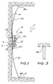
- FIG. 1 is a side view of an embodiment of a support device according to the present invention, in a disengaged position;
- FIG. 2 is a side view of the support device shown in FIG. 1 in an engaged position
- FIG. 3 is a partial front view of the device shown in FIG. 2 .
- FIGS. 1 , 2 and 3 show an embodiment of a support device, generally indicated by the reference numeral 8 , according to the invention.
- the device 8 includes an expansion means (expander) 10 that includes an inner square hollow section (SHS) steel member 20 that slides within an outer SHS steel member 22 .
- the expansion means 10 also includes a jacking arrangement welded to the member 22 , that includes a jacking lever 24 , and a ratchet device 26 welded to the first member 20 .
- the device 8 also includes a pair of curved resilient members 12 a , 12 b formed from pre-curved spring steel. Both of the members 12 a and 12 b are welded to the members 20 and 22 respectively at their proximal ends 27 a and 27 b.
- the resilient members 12 a and 12 b are oppositely extending and have distal ends 28 a, 28 b curved away from the expansion means 10 .
- the distal ends 28 a, 28 b terminate with a saw-tooth profile.
- the support device 8 is positioned such that the distal ends 28 a, 28 b of each of the resilient members 12 a, 12 b are placed near the floor 18 and roof 16 respectively of an underground roadway and close to the rib 14 .
- the device 8 is oriented such that the distal ends 28 a, 28 b of the resilient members 12 a, 12 b curve away from the rib 14 .
- the jacking lever 24 is then manually operated such that a pawl (not shown) engages with the ratchet device 26 to effect relative expanding movement between the members 20 and 22 .
- This movement drives the resilient members 12 a, 12 b away from each other, in the directions indicated by vertical arrows 30 in FIG. 1 , and drives the ends 28 a and 28 b of the resilient members 12 a and 12 b into engagement with the floor 18 and roof 16 respectively, as shown in FIG. 2 .
- the saw-tooth profile of the members distal ends 28 a and 28 b assists them in securely engaging with the roof 16 and floor 18 .
- the jag lever 24 results in the members 12 a, 12 b, bowing under tension towards the rib 14 which drives a portion of the device 8 adjacent the expansion means 10 laterally, in the direction of horizontal arrow 32 in FIG. 1 , into abutment against the rib 14 .
- the device 8 As the device 8 is forced into abutment against the rib 14 , it thereby resists movement of the rib 14 in the opposite direction to the arrow 32 and advantageously provides support against failure of the rib 14 in that opposite direction.
- a number of the devices 8 would typically be placed spaced apart along a section of roadway need support.
- an advantage of the device 8 is it can be quickly and easily locked into a position supporting of the rib 14 .
- the device 8 can be also used with other rib support systems (ie. steel or plastic mesh) interposed between the device 8 and the rib 14 and offer support with or without the installation of rib bolts.
- rib support systems ie. steel or plastic mesh
- Another advantage of the device 8 is that if any lateral movement of the rib 14 occurs during use, the distal ends of the resilient members 12 a, 12 b are forced more strongly into the floor 18 and roof 16 which assists in retaining the device 8 in position.
- a further advantage of support device 8 is that it can be easily and quickly retracted from the rib 14 by releasing the ratchet device 26 for re-use at a later stage in the mining cycle or, alternatively, left as a permanent support.
- the expansion means 10 can be activated to expand by other mechanical components (such as screws), hydraulically (such as hydraulic cylinders) or pneumatically (such as, pneumatic cylinders),
- the expansion means 10 can be disengaged from the remainder of the support device 8 , after the resilient members 12 a and 12 b have been driven into engagement with the roof 16 and floor 18 .
- each member 20 and 22 can include one or more holes spaced along it's length.
- a pin 34 or other such fastener can be inserted through two corresponding holes 36 , 38 (when aligned) in the members 20 and 22 respectfully to lock the support device 8 in an engaged/abutted position. This permits a single expansion means 10 to be disengaged and utilised during the expansion and placement of multiple rib support devices 8 .
Landscapes
- Engineering & Computer Science (AREA)
- Mining & Mineral Resources (AREA)
- Mechanical Engineering (AREA)
- Structural Engineering (AREA)
- Life Sciences & Earth Sciences (AREA)
- General Life Sciences & Earth Sciences (AREA)
- Geochemistry & Mineralogy (AREA)
- Geology (AREA)
- Emergency Lowering Means (AREA)
- Mutual Connection Of Rods And Tubes (AREA)
Abstract
Description
-
- an expansion means; and
- a pair of resilient members each having a proximal end adapted for connection to the expansion means and a distal end curved away from the expansion means and adapted for engagement with the floor and roof respectively,
- wherein when the device is positioned towards or against the rib and the expansion means is activated to drive the members apart, the members distal ends are driven substantially vertically into engagement with the floor and the roof and a portion of the device is driven substantially laterally into abutment against the rib.
-
- an expander; and
- a pair of resilient members each having a proximal end adapted for connection to the expander and a distal end curved away from the expander.
Claims (20)
Applications Claiming Priority (2)
| Application Number | Priority Date | Filing Date | Title |
|---|---|---|---|
| AU2002951470A AU2002951470A0 (en) | 2002-09-18 | 2002-09-18 | A support device for a rib |
| AU2002951470 | 2002-09-18 |
Publications (2)
| Publication Number | Publication Date |
|---|---|
| US20050257448A1 US20050257448A1 (en) | 2005-11-24 |
| US7490440B2 true US7490440B2 (en) | 2009-02-17 |
Family
ID=28047225
Family Applications (1)
| Application Number | Title | Priority Date | Filing Date |
|---|---|---|---|
| US10/663,438 Expired - Fee Related US7490440B2 (en) | 2002-09-18 | 2003-09-16 | Support device for a rib |
Country Status (3)
| Country | Link |
|---|---|
| US (1) | US7490440B2 (en) |
| AU (1) | AU2002951470A0 (en) |
| ZA (1) | ZA200307277B (en) |
Cited By (3)
| Publication number | Priority date | Publication date | Assignee | Title |
|---|---|---|---|---|
| US20100054870A1 (en) * | 2007-11-19 | 2010-03-04 | Jennmar Corporation | Mine roof and rib support with reinforced channel |
| US20110052334A1 (en) * | 2009-09-01 | 2011-03-03 | Breedlove John J | Apparatus and method for supporting a mine rib |
| US20110250024A1 (en) * | 2010-04-12 | 2011-10-13 | Fci Holdings Delaware Inc. | Mine Roof and Rib Support with Vertical Bolt |
Families Citing this family (3)
| Publication number | Priority date | Publication date | Assignee | Title |
|---|---|---|---|---|
| USD647770S1 (en) * | 2010-02-25 | 2011-11-01 | Vertex Stone and Chinaware Ltd. | Cam tool |
| CN106013808B (en) * | 2016-06-30 | 2019-01-18 | 湖南五新模板有限公司 | It is a kind of to pave the concrete speading equipment of function with curved surface |
| CN110284717A (en) * | 2019-04-24 | 2019-09-27 | 中国一冶集团有限公司 | Super-long-and-Large-area is seamless concrete construction method |
Citations (34)
| Publication number | Priority date | Publication date | Assignee | Title |
|---|---|---|---|---|
| US1229323A (en) * | 1912-12-09 | 1917-06-12 | James J Roby | Meand for supporting the roofs of mine-entries. |
| US1576521A (en) * | 1925-09-17 | 1926-03-16 | Laser Emil | Carpenter's work support |
| US1766324A (en) * | 1929-02-09 | 1930-06-24 | Vernon T Berner | Brattice |
| US2068491A (en) * | 1936-02-07 | 1937-01-19 | Templeton Kenly & Co Ltd | Mine roof jack |
| US2138494A (en) * | 1936-11-21 | 1938-11-29 | Thomas B Knox | Curve plotting and drafting instrument |
| US2556357A (en) * | 1948-10-29 | 1951-06-12 | John C Baldwin | Combined mine drill, timber jack, and mine post |
| US3126708A (en) * | 1964-03-31 | Karl-theodor jasper | ||
| US3206187A (en) * | 1962-01-12 | 1965-09-14 | Wilburn C Cagley | Swinging check curtain |
| US3636852A (en) * | 1970-05-11 | 1972-01-25 | Burgess James V Jun | Mine ventilation control system |
| US3747503A (en) * | 1971-03-24 | 1973-07-24 | P Lovell | Mine ventilation control system |
| US3863420A (en) * | 1974-02-13 | 1975-02-04 | Thorpe Co J T | Apparatus for installing bricks in a kiln |
| US3891275A (en) * | 1972-11-25 | 1975-06-24 | Bochumer Eisen Heintzmann | Mobile mine roof support with mining apparatus |
| US4091628A (en) * | 1976-09-27 | 1978-05-30 | Jay Hilary Kelley | Prestressed elastic arched mine roof support |
| US4173421A (en) * | 1976-10-15 | 1979-11-06 | Gewerkschaft Eisenhutte Westfalia | Shield apparatus for use in tunnelling or mining |
| US4334800A (en) * | 1979-09-19 | 1982-06-15 | Gewerkschaft Eisenhutte Westfalia | Tunnel drive shield |
| US4349300A (en) * | 1979-06-04 | 1982-09-14 | Kelley Jay H | Systemic roof support |
| US4770086A (en) * | 1987-08-20 | 1988-09-13 | Gabster Jeffrey C | Portable ventilation safety device |
| US4997317A (en) * | 1988-02-26 | 1991-03-05 | Neuero Stahllau Gmbh & Co. | System and method for supporting a mining gallery |
| US5103531A (en) * | 1990-08-27 | 1992-04-14 | Joseph Perrotta | Shower bow |
| US5316407A (en) * | 1992-07-15 | 1994-05-31 | Miller Wayborn M | Manhole cover support |
| US5564866A (en) * | 1995-04-10 | 1996-10-15 | Snyder; Raymond M. | Reusable mine and underground roof, floor, and rib support system |
| US5683294A (en) * | 1996-09-16 | 1997-11-04 | Maines; Teddy | Temporary brattice for mines |
| US5890856A (en) * | 1998-06-05 | 1999-04-06 | Huang; Han-Ching | Crossbar device for limiting cargoes from falling |
| US5934990A (en) * | 1997-04-16 | 1999-08-10 | The Tensar Corporation | Mine stopping |
| US6102628A (en) * | 1998-03-30 | 2000-08-15 | Council Of Scientific & Industrial Research | Arch useful for withstanding effect of rockburst occurring in underground mines/tunnels |
| US6216287B1 (en) * | 1995-07-03 | 2001-04-17 | Sean Moore | Shower curtain rod |
| US6368037B1 (en) * | 2000-08-11 | 2002-04-09 | Multiprens C.A. | Cargo bar with easy release and force limitation |
| US6499916B2 (en) * | 1999-04-14 | 2002-12-31 | American Commercial Inc. | Compressible support column |
| US6694543B2 (en) * | 2002-05-21 | 2004-02-24 | Sean A. Moore | Compression mount for a shower curtain rod |
| US6733220B2 (en) * | 2002-08-15 | 2004-05-11 | Usa Products Group, Inc. | Cargo bar |
| US20050268394A1 (en) * | 2004-05-14 | 2005-12-08 | Elizabeth Monk | Telescoping expandable shower curtain rod |
| US7114888B2 (en) * | 2002-02-22 | 2006-10-03 | Jennmar Corporation | Yieldable prop |
| US20070174956A1 (en) * | 2005-12-20 | 2007-08-02 | David Heaslip | Adjustable shower rod assembly |
| US7263746B2 (en) * | 2004-08-11 | 2007-09-04 | Press-Seal Gasket Corporation | Expansion ring assembly with removable drive mechanism |
-
2002
- 2002-09-18 AU AU2002951470A patent/AU2002951470A0/en not_active Abandoned
-
2003
- 2003-09-16 US US10/663,438 patent/US7490440B2/en not_active Expired - Fee Related
- 2003-09-17 ZA ZA200307277A patent/ZA200307277B/en unknown
Patent Citations (34)
| Publication number | Priority date | Publication date | Assignee | Title |
|---|---|---|---|---|
| US3126708A (en) * | 1964-03-31 | Karl-theodor jasper | ||
| US1229323A (en) * | 1912-12-09 | 1917-06-12 | James J Roby | Meand for supporting the roofs of mine-entries. |
| US1576521A (en) * | 1925-09-17 | 1926-03-16 | Laser Emil | Carpenter's work support |
| US1766324A (en) * | 1929-02-09 | 1930-06-24 | Vernon T Berner | Brattice |
| US2068491A (en) * | 1936-02-07 | 1937-01-19 | Templeton Kenly & Co Ltd | Mine roof jack |
| US2138494A (en) * | 1936-11-21 | 1938-11-29 | Thomas B Knox | Curve plotting and drafting instrument |
| US2556357A (en) * | 1948-10-29 | 1951-06-12 | John C Baldwin | Combined mine drill, timber jack, and mine post |
| US3206187A (en) * | 1962-01-12 | 1965-09-14 | Wilburn C Cagley | Swinging check curtain |
| US3636852A (en) * | 1970-05-11 | 1972-01-25 | Burgess James V Jun | Mine ventilation control system |
| US3747503A (en) * | 1971-03-24 | 1973-07-24 | P Lovell | Mine ventilation control system |
| US3891275A (en) * | 1972-11-25 | 1975-06-24 | Bochumer Eisen Heintzmann | Mobile mine roof support with mining apparatus |
| US3863420A (en) * | 1974-02-13 | 1975-02-04 | Thorpe Co J T | Apparatus for installing bricks in a kiln |
| US4091628A (en) * | 1976-09-27 | 1978-05-30 | Jay Hilary Kelley | Prestressed elastic arched mine roof support |
| US4173421A (en) * | 1976-10-15 | 1979-11-06 | Gewerkschaft Eisenhutte Westfalia | Shield apparatus for use in tunnelling or mining |
| US4349300A (en) * | 1979-06-04 | 1982-09-14 | Kelley Jay H | Systemic roof support |
| US4334800A (en) * | 1979-09-19 | 1982-06-15 | Gewerkschaft Eisenhutte Westfalia | Tunnel drive shield |
| US4770086A (en) * | 1987-08-20 | 1988-09-13 | Gabster Jeffrey C | Portable ventilation safety device |
| US4997317A (en) * | 1988-02-26 | 1991-03-05 | Neuero Stahllau Gmbh & Co. | System and method for supporting a mining gallery |
| US5103531A (en) * | 1990-08-27 | 1992-04-14 | Joseph Perrotta | Shower bow |
| US5316407A (en) * | 1992-07-15 | 1994-05-31 | Miller Wayborn M | Manhole cover support |
| US5564866A (en) * | 1995-04-10 | 1996-10-15 | Snyder; Raymond M. | Reusable mine and underground roof, floor, and rib support system |
| US6216287B1 (en) * | 1995-07-03 | 2001-04-17 | Sean Moore | Shower curtain rod |
| US5683294A (en) * | 1996-09-16 | 1997-11-04 | Maines; Teddy | Temporary brattice for mines |
| US5934990A (en) * | 1997-04-16 | 1999-08-10 | The Tensar Corporation | Mine stopping |
| US6102628A (en) * | 1998-03-30 | 2000-08-15 | Council Of Scientific & Industrial Research | Arch useful for withstanding effect of rockburst occurring in underground mines/tunnels |
| US5890856A (en) * | 1998-06-05 | 1999-04-06 | Huang; Han-Ching | Crossbar device for limiting cargoes from falling |
| US6499916B2 (en) * | 1999-04-14 | 2002-12-31 | American Commercial Inc. | Compressible support column |
| US6368037B1 (en) * | 2000-08-11 | 2002-04-09 | Multiprens C.A. | Cargo bar with easy release and force limitation |
| US7114888B2 (en) * | 2002-02-22 | 2006-10-03 | Jennmar Corporation | Yieldable prop |
| US6694543B2 (en) * | 2002-05-21 | 2004-02-24 | Sean A. Moore | Compression mount for a shower curtain rod |
| US6733220B2 (en) * | 2002-08-15 | 2004-05-11 | Usa Products Group, Inc. | Cargo bar |
| US20050268394A1 (en) * | 2004-05-14 | 2005-12-08 | Elizabeth Monk | Telescoping expandable shower curtain rod |
| US7263746B2 (en) * | 2004-08-11 | 2007-09-04 | Press-Seal Gasket Corporation | Expansion ring assembly with removable drive mechanism |
| US20070174956A1 (en) * | 2005-12-20 | 2007-08-02 | David Heaslip | Adjustable shower rod assembly |
Cited By (5)
| Publication number | Priority date | Publication date | Assignee | Title |
|---|---|---|---|---|
| US20100054870A1 (en) * | 2007-11-19 | 2010-03-04 | Jennmar Corporation | Mine roof and rib support with reinforced channel |
| US8197160B2 (en) | 2007-11-19 | 2012-06-12 | Fci Holdings Delaware, Inc. | Mine roof and rib support with reinforced channel |
| US20110052334A1 (en) * | 2009-09-01 | 2011-03-03 | Breedlove John J | Apparatus and method for supporting a mine rib |
| US8371658B2 (en) | 2009-09-01 | 2013-02-12 | Heintzmann Corporation | Apparatus and method for supporting a mine rib |
| US20110250024A1 (en) * | 2010-04-12 | 2011-10-13 | Fci Holdings Delaware Inc. | Mine Roof and Rib Support with Vertical Bolt |
Also Published As
| Publication number | Publication date |
|---|---|
| AU2002951470A0 (en) | 2002-10-03 |
| ZA200307277B (en) | 2004-07-01 |
| US20050257448A1 (en) | 2005-11-24 |
Similar Documents
| Publication | Publication Date | Title |
|---|---|---|
| US3972272A (en) | Mine brattice | |
| CA2741272C (en) | High-strength anchor system, safe room bulkhead, and method of anchoring a support to mine strata | |
| AU2011242670B2 (en) | Pumpable support with cladding | |
| GB2349400A (en) | Permanent mine stopping | |
| US6715961B2 (en) | Method of supporting mine walls and installing a mine stopping | |
| CA2449682C (en) | Rock bolt and method of use | |
| US7490440B2 (en) | Support device for a rib | |
| GB2441018A (en) | Rock bolt and method of use | |
| US2889614A (en) | Method of making tubular, pronged reinforcing members for rock strata | |
| AU2011236039B2 (en) | Rock bolt hanger system | |
| US7794181B2 (en) | Mine roof and rib support device | |
| AU2003248009B2 (en) | A Support Device For a Rib | |
| KR940701486A (en) | How to install ground anchors and ground anchors | |
| US4523881A (en) | Lateral force system and support for supporting mine roofs | |
| KR20210000728U (en) | simultaneous grouting packer | |
| KR101445369B1 (en) | Soil Nailing Device Using Connector and Construction Method Using the Same | |
| US4415294A (en) | Support means and system for supporting mine roofs | |
| US20110250024A1 (en) | Mine Roof and Rib Support with Vertical Bolt | |
| US20190178083A1 (en) | Yieldable Bearing Block | |
| KR200263938Y1 (en) | Support equipment for earth anchor fixing | |
| AU2004202519A1 (en) | Friction bolt | |
| CA2089971C (en) | Metal clip and tool for closing the same | |
| DE3019336A1 (en) | Mine gallery segmented support system recovery harness - has hydraulic thrust piston pressure plate and clamp with clamp plate | |
| GB2236128A (en) | Arch support system | |
| JPH10169393A (en) | Friction bolt and its fixing method |
Legal Events
| Date | Code | Title | Description |
|---|---|---|---|
| AS | Assignment |
Owner name: HOOPER, RICHARD DURMAN, AUSTRALIA Free format text: ASSIGNMENT OF ASSIGNORS INTEREST;ASSIGNOR:BATTY, DERREK WILLIAM;REEL/FRAME:014966/0117 Effective date: 20040112 Owner name: BATTY, DERREK WILLIAM, AUSTRALIA Free format text: ASSIGNMENT OF ASSIGNORS INTEREST;ASSIGNOR:BATTY, DERREK WILLIAM;REEL/FRAME:014966/0117 Effective date: 20040112 |
|
| REMI | Maintenance fee reminder mailed | ||
| LAPS | Lapse for failure to pay maintenance fees | ||
| STCH | Information on status: patent discontinuation |
Free format text: PATENT EXPIRED DUE TO NONPAYMENT OF MAINTENANCE FEES UNDER 37 CFR 1.362 |
|
| FP | Lapsed due to failure to pay maintenance fee |
Effective date: 20130217 |