US7486463B1 - Power disturbance compensation - Google Patents
Power disturbance compensation Download PDFInfo
- Publication number
- US7486463B1 US7486463B1 US11/975,441 US97544107A US7486463B1 US 7486463 B1 US7486463 B1 US 7486463B1 US 97544107 A US97544107 A US 97544107A US 7486463 B1 US7486463 B1 US 7486463B1
- Authority
- US
- United States
- Prior art keywords
- disturbance
- compensation
- power
- power supply
- deriving
- Prior art date
- Legal status (The legal status is an assumption and is not a legal conclusion. Google has not performed a legal analysis and makes no representation as to the accuracy of the status listed.)
- Expired - Fee Related
Links
Images


Classifications
-
- G—PHYSICS
- G11—INFORMATION STORAGE
- G11B—INFORMATION STORAGE BASED ON RELATIVE MOVEMENT BETWEEN RECORD CARRIER AND TRANSDUCER
- G11B5/00—Recording by magnetisation or demagnetisation of a record carrier; Reproducing by magnetic means; Record carriers therefor
- G11B5/48—Disposition or mounting of heads or head supports relative to record carriers ; arrangements of heads, e.g. for scanning the record carrier to increase the relative speed
- G11B5/54—Disposition or mounting of heads or head supports relative to record carriers ; arrangements of heads, e.g. for scanning the record carrier to increase the relative speed with provision for moving the head into or out of its operative position or across tracks
- G11B5/55—Track change, selection or acquisition by displacement of the head
- G11B5/5521—Track change, selection or acquisition by displacement of the head across disk tracks
- G11B5/5582—Track change, selection or acquisition by displacement of the head across disk tracks system adaptation for working during or after external perturbation, e.g. in the presence of a mechanical oscillation caused by a shock
-
- G—PHYSICS
- G11—INFORMATION STORAGE
- G11B—INFORMATION STORAGE BASED ON RELATIVE MOVEMENT BETWEEN RECORD CARRIER AND TRANSDUCER
- G11B19/00—Driving, starting, stopping record carriers not specifically of filamentary or web form, or of supports therefor; Control thereof; Control of operating function ; Driving both disc and head
- G11B19/02—Control of operating function, e.g. switching from recording to reproducing
- G11B19/04—Arrangements for preventing, inhibiting, or warning against double recording on the same blank or against other recording or reproducing malfunctions
- G11B19/041—Detection or prevention of read or write errors
Definitions
- This invention relates generally to the field of servo control systems and specifically mitigating the effects of power supply disturbances on a servo control system's performance.
- a servo system is a control system that controls the operation of an apparatus through a series of feedback signals to the control system.
- the feedback signal is typically from a sensor that determines the offset of the actual operation of the apparatus from the requested operation of the apparatus.
- Some examples of servo systems are: a thermostat for controlling the temperature of a room; an autopilot for controlling the flying attitude and direction of an aircraft; a cruise control for controlling the speed of an automobile; a servo system in a hard disk drive (HDD) for controlling disk RPM and magnetic transducer position.
- HDD hard disk drive
- servo systems are challenged by external disturbances that can cause them to over or under react in the control of the operation of the apparatus.
- external disturbances, and over and under reaction they may cause are: the air conditioning of a room may not be adjusted quickly or may cool a room too much in response to changing thermal loads; an aircraft may not respond smoothly or accurately to wind or barometric conditions to maintain an attitude or direction of the aircraft; an HDD may not react in a timely manner to demands for data from the HDD.
- An HDD is one example of many possible examples of a mechanism using a servo system.
- One of ordinary skill in the art will appreciate that embodiments of the present invention are beneficial to a variety of mechanisms operable to a control or servo system.
- the HDD will be used for the sake of brevity and clarity to demonstrate the need for a well-controlled servo system and a servo system's vulnerability to problems.
- Direct access storage devices have become part of every day life, and as such, expectations and demands continually increase for greater speed for manipulating data and for holding larger amounts of data. To meet these demands for increased performance, the mechanical assembly in a DASD device, specifically the HDD, has undergone many changes.
- the amount of data that can be stored on a disk is governed by many well-known physical principles.
- One factor in determining the amount of data that can be stored in an HDD is the ability of the magnetic transducer to write closely spaced data tracks onto the disk surface.
- the spacing of tracks on a disk surface is known as track pitch, and the unit of measure for expressing the density of tracks on a disk is tracks per inch or TPI.
- TPI tracks per inch
- the servo system of the HDD enables in part the magnetic transducer to be precisely positioned at a radius on the disk to write a data track, enabling adjacent data tracks to be written with a high TPI.
- the HDD must be able to find the track and settle upon it in a minimal amount of time. This amount of time is typically known as seek-settle time, and when coupled with the time for the data to rotate to where it can be read and the time required for the HDD to decipher the data on the track, this total time is known as latency.
- An HDD user usually prefers short latency.
- the robustness of the servo system will determine if the magnetic transducer has settled on a desired data track or needs to make another attempt at settling on the data track. Spurious electrical and/or mechanical noise can degrade the servo system and require it to make multiple attempts at reading data. The susceptibility of a servo system to spurious noise may prevent the magnetic transducer from being positioned in a sufficiently precise manner to allow a desired TPI.
- a method for compensating for a disturbance in power from a power supply wherein the disturbance without the compensating would otherwise affect a positioning apparatus coupled to the power supply.
- the method comprises receiving the disturbance in power from the power supply, deriving a compensation for the disturbance in the power, and transmitting the compensation to a control system for the positioning apparatus.
- FIG. 1 is an isometric blow-apart of an HDD in accordance with one embodiment of the present invention.
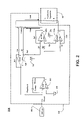
- FIG. 2 is a schematic of a transconductance amplifier operable to embodiments of the present invention.
- FIG. 3 is a block diagram of a system for compensating for a disturbance in power from a power supply in accordance with one embodiment of the present invention.
- FIG. 4 is a flow chart illustrating a process for compensating for a disturbance in power from a power supply in accordance with one embodiment of the present invention.
- the discussion will focus on an HDD as an example of a mechanism operable to a control and/or servo system that benefits from the embodiments of the present invention.
- the discussion will begin with a description and overview of a control system and a servo system.
- the discussion will then focus on embodiments of the present invention by which compensating for a disturbance in power from a power supply coupled with a control or servo system is implemented.
- Base casting 113 provides coupling points for components and sub-assemblies such as disk stack 158 , voice coil motor (VCM) 142 , and head stack assembly (HSA) 120 .
- Disk stack 158 is coupled with base casting 113 by means of motor-hub assembly 140 and disk clamp 143 .
- Motor-hub assembly 140 will have at least one disk 156 coupled with it such that disk 156 can rotate about an axis common to motor-hub assembly 140 and the center of disk 156 .
- Disk 156 has at least one disk surface 130 upon which reside data tracks 135 .
- HSA 120 sometimes referred to as an actuator assembly or carriage, comprises suspension 127 , which suspends hard disk drive slider 125 next to disk surface 130 , and HSA connector 116 .
- Suspension 127 and hard disk drive slider 125 comprise head gimbal assembly (HGA) 128 .
- Flex cable 110 which is part of HSA 120 , conveys data between HSA connector 116 and arm electronics (A/E) module 115 .
- HSA connector 116 also conveys control data between printed circuit board (PCB) 160 and VCM 142 .
- PCB printed circuit board
- HSA 120 is coupled pivotally with base casting 113 by means of pivot bearing 145 , such that VCM 142 can move HGA 128 with slider 125 arcuately across disk surface 130 , accessing data tracks 135 .
- cover 112 is coupled with base casting 113 to enclose these components and sub-assemblies into HDD 100 .
- PCB 160 is coupled to base casting 113 .
- PCB 160 comprises at least one electrical component 165 which in general performs the electrical tasks of HDD 100 , such as status check of HDD 100 before writing data, power control for motor-hub assembly 140 , and servo control of VCM 142 .
- VCM 142 is electrically coupled with PCB 160 via HSA connector 116 and an appropriately mating connection 167 on PCB 160 . Electrical coupling of HDD 100 to a host system in which HDD 100 operates is enabled in part through PCB connector 163 , coupled to PCB 160 .
- HDD 100 can be used in a variety of operating configurations, such as a single HDD in a computer, and in conjunction with several other HDDs in a rack.
- Power is supplied to the HDD usually from a single power supply.
- This power supply may also supply power to other devices in the computing system, such as a fan, an external hard drive, an auxiliary back-up system, and other HDDs in the rack.
- the power available from the power supply can fluctuate depending upon the power draw of the other devices it supports.
- adjacent HDDs can be performing different operations with different power demands, such as one drive could be track following while another could be seeking and trying to settle on data, while another is booting up to come on line.
- the operation of HDDs in a rack can affect mechanically and electrically the operation of a neighboring HDD mounted in the rack.
- Power fluctuations from a power supply can cause disturbance in the power driving VCM 142 and affect the positioning accuracy and seek-settle time of HSA 120 .
- Power fluctuations are specified as ripple and assigned a tolerance for AC fluctuations in the DC output of a power supply. The actual fluctuations from a power supply are not known until the power supply is operational.
- PCB connector 163 electrically couples HDD 100 to a power supply to receive power
- PCB connector 163 also receives power fluctuations from the power supply. Since PCB connector 163 is coupled with VCM 142 via HSA connector 116 and mating connector 167 , power fluctuations from a power supply can affect how VCM 142 moves HGA 128 with slider 125 arcuately across disk surface 130 to access data tracks 135 .
- an HDD as a mechanism operable to a control and/or servo system that benefits from the embodiments of the present invention most commonly operates with a control system that comprises a servo system with a servo loop.
- the servo loop of the servo system of an HDD feeds back positional information of slider 125 to a position controller, whereby adjustments can be made to the actual position of slider 125 to meet more closely the requested position of slider 125 .
- HDD 100 a control system is used wherein the servo loop and servo system are not engaged.
- An example of the manufacturing process of HDD 100 in which a servo loop and servo system are not engaged is during servo write, whereby VCM 142 is controlled by a control system running open loop without the feedback of a servo loop and hence without a servo system.
- Embodiments of the present invention benefit HDD 100 running open loop with a control system controlling VCM 142 and with HDD 100 running closed loop with a servo system and servo loop controlling VCM 142 . Power fluctuations can be detrimental to the motion control of VCM 142 whether VCM 142 is being controlled by a control system or a servo system.
- schematic 200 of transconductance (g m ) amplifier 210 is presented as operable to embodiments of the present invention.
- Gm amplifier 210 is known and understood in the art for providing a current that is proportional to a voltage that it receives.
- Gm amplifier 210 is commonly used in control systems for controlling an apparatus such as positioning apparatus 250 .
- An example of positioning apparatus 250 is presented in FIG. 1 as VCM 142 for positioning slider 125 adjacent to data tracks 135 .
- At least one electrical component 165 coupled to PCB 160 comprises g m amplifier 210 .
- digital-to-analog converter output, (DAC out) 205 converts a digital voltage of a control command to an analog voltage of a control command, and presents it to g m amplifier 210 for processing.
- Inherent in g m amplifier 210 is one or more voltage reference Vref 215 which provides at least one reference voltage to error amplifier 220 , power amplifier ( 230 a , 230 b ), and/or current sensing amplifier 240 .
- Vref 215 is typically half of the voltage delivered by the power supply. Since Vref 215 is electrically coupled with the power supply voltage, the performance of error amplifier 220 , power amplifier ( 230 a , 230 b ), and current sensing amplifier 240 is affected by a disturbance in the power supply voltage.
- each amplifier is an array of electrical components. For example, associated with sensing amplifier 240 are sense feedback resistors Rsf, and sense input resistors Rsi. There are similarly associated components for error amplifier 220 and power amplifier ( 230 a , 230 b ). Each of these components has its own inherent performance or tolerance for its expected electrical parameter. In turn, the tolerance of each electrical component affects the performance of the associated amplifiers, and the performance of g m amplifier 210 . The performance of g m amplifier 210 has specified tolerances. Today's tolerance of g m amplifier 210 is insufficient to achieve smaller track pitch goals for recording data tracks 135 and to meet the seek-settle time goals for manipulating data on data tracks 135 .
- System 310 is a system for compensating for disturbance 325 in power from power supply 320 .
- System 310 is coupled with positioning apparatus 250 . Without the benefits of the embodiments of the present invention, disturbance 325 would otherwise affect positioning apparatus 250 in an undesirable manner.
- Summation node 395 receives both disturbance 325 from power supply 320 and an analog conversion from DAC out 205 .
- Power from power supply 320 comprises disturbance 325 and is transmitted to amplifier 210 , such as g m amplifier 210 , via summation node 395 .
- Amplifier 210 amplifies the analog current output commanded from DAC out 205 .
- the analog current output from DAC out 205 is added with disturbance 325 by summation node 395 .
- block diagram 300 of system 310 presents amplifier 210 as a transconductance (g m ) amplifier.
- amplifier 210 is, in accordance with another embodiment of the present invention, a voltage amplifier.
- other elements of system 310 would be changed from current based current-based elements to voltage-based elements, without detracting from the spirit or intent of the embodiments of the present invention.
- positioning apparatus current 345 which is the output of g m amplifier 210 , would change to positioning apparatus voltage.
- filtering device 330 receives disturbance 325 from power supply 320 .
- Filtering device 330 is a compensation-deriving device that filters the frequency content of disturbance 325 and derives frequency compensation 337 for disturbance 325 .
- filtering device 330 is a filtering device selected from the group of filtering devices consisting of: an all-pass filter, a lead-lag filter, a notch filter, a band-pass filter, a high-pass filter, a peak filter, and a low-pass filter.
- Filtering device 330 presents frequency compensation 337 to summation node 393 .
- frequency compensation 337 which is derived by filtering device 330 , is received by summation node 393 .
- Filtering device 330 is coupled with DAC out 205 , which is comprised within servo loop 390 for positioning apparatus 250 .
- frequency compensation 337 is transmitted to DAC out 205 , which is coupled with g m amplifier 210 .
- gain compensation 377 b which is derived by gain computing device 370 b , is received by summation node 393 .
- Gain computing device 370 b is coupled with DAC out 205 , which is comprised within servo loop 390 for positioning apparatus 250 .
- positioning apparatus 250 comprises VCM 142 and HSA 120 coupled with HDD 100 .
- Power supply 320 is coupled with HDD 100 and filtering device 330 , whereby disturbance 325 from power supply 320 is compensated.
- Summation node 397 receives positioning apparatus current 345 from g m amplifier 210 and also receives mechanical bias 340 .
- Mechanical bias 340 is the result of a variety of mechanical disturbances that affect the position of positioning apparatus 250 .
- Some examples of mechanical bias 340 are: vibration from neighboring HDDs in a rack; spring force from flex cable 110 exerted on HSA 120 ; wind force from rotating disk stack 158 pushing on HSA 120 .
- This list of examples of mechanical bias 340 is not intended to be an exhaustive and complete list of mechanical biases that can effect the position of HSA 120 and hence slider 125 . This list is presented only for the sake of brevity and illustration.
- Positioning apparatus 250 moves in accordance with the summation of positioning apparatus current 345 and mechanical bias 340 and results in positioning apparatus motion 355 .
- Summation node 399 receives positioning apparatus motion 355 and reference position 350 .
- Reference position 350 is the desired position of positioning apparatus 250 that is expected to result from positioning apparatus current 345 .
- summation node 399 compares reference position 350 with positioning apparatus motion 355 and presents position error signal (PES) 360 to gain computing device 370 a .
- gain computing device 370 b receives frequency compensation 337 from filter device 330 and derives gain compensation 377 b which is transmitted to summation node 393 , where it is added with control command 387 .
- Gain computing device 370 a receives PES 360 and derives gain compensation 377 a for disturbance 325 from power supply 320 .
- Gain compensation ( 377 a , 377 b ) comprises amplitude for frequency compensation 337 .
- Gain compensation 377 a is transmitted to position controller 380 which issues control command 387 .
- Control command 387 is added with frequency compensation 337 at summation node 393 .
- FIG. 4 is a flow chart illustrating a process 400 for compensating for a disturbance in power from a power supply in accordance with an embodiment of the present invention.
- the disturbance without the compensating would otherwise affect a positioning apparatus coupled to the power supply.
- process 400 is operable to compensating for a disturbance in power from a power supply coupled with a control system for a positioning apparatus.
- process 400 is coupled with a servo system operable to a hard disk drive, whereby the disturbance in power, which can enter the hard disk drive, is compensated thus providing mitigation of an affect of the disturbance in power on the servo loop of the hard disk drive.
- a control system operational without a servo loop and a servo system operational with a servo loop both benefit from embodiments of the present invention.
- Both a control system and a servo system can be adversely affected by a disturbance in power from a power supply and influence the motion of a positioning apparatus which the control system or servo system are operating. Mitigating the effect of a disturbance in power from a power supply can improve the accuracy of movement of the positioning apparatus being operated by either a control system or a servo system.
- processors and electrical components under the control of computer readable and computer executable instructions carry out process 400 .
- the computer readable and computer executable instructions reside, for example, in data storage features such as computer usable volatile and non-volatile memory.
- the computer readable and computer executable instructions may reside in any type of computer readable medium.
- specific components are disclosed in process 400 , such components are examples of components for carrying out process 400 . That is, the embodiments of the present invention are well suited to performing various other components or variations of the components recited in FIG. 4 .
- the components of process 400 may be performed by software, by hardware, by an assembly mechanism, through human interaction, or by any combination of software, hardware, assembly mechanism, and human interaction.
- Process 400 will be described with reference to elements shown in FIG. 2 and FIG. 3 .
- a power supply is provided. If there is not a disturbance or fluctuation in the power from the power supply, the operation of the control system or servo system in which process 400 is to operate is not affected by embodiments of the present invention. Embodiments of the present invention are beneficial during episodes of disturbance in the power from the power supply.
- a disturbance in the power from the power supply is received.
- summation node 395 receives both disturbance 325 from power supply 320 and an analog conversion from DAC out 205 .
- Power from power supply 320 comprises disturbance 325 and is transmitted to amplifier 210 via summation node 395 .
- Amplifier 210 amplifies the analog current output requested from DAC out 205 which comprises disturbance 325 .
- a compensation for disturbance 325 is derived.
- Disturbance 325 comprises a frequency component and an amplitude or gain component.
- element 430 of process 400 comprises deriving frequency compensation 337 using a filtering device such as filtering device 330 presented in block diagram 300 of system 310 .
- a filtering device for deriving frequency compensation is selected from the group of filtering devices consisting of: an all-pass filter, a lead-lag filter, a notch filter, a band-pass filter, a high-pass filter, a peak filter, and a low-pass filter.
- Deriving frequency compensation using a filter device such as filtering device 330 comprises passing a frequency at approximately 180° out of phase with a disturbance such as disturbance 325 .
- Frequency compensation 337 is a compensation for the frequency content of disturbance 325 in power from power supply 320 .
- Filtering device 330 is coupled with power supply 320 .
- element 430 of process 400 comprises deriving gain compensation ( 377 a , 377 b ) using a gain computing device such as gain computing device ( 370 a , 370 b ) presented in block diagram 300 of system 310 .
- Gain computing device ( 370 a , 370 b ) for deriving gain compensation ( 377 a , 377 b ) comprises a series of element relationships and relational equations which link elements of a servo loop 390 , whereby gain compensation ( 377 a , 377 b ) for power disturbance 325 is derived.
- the relational equations which link elements of a servo loop 390 are expressed with respect to elements of system 310 are defined as follows: PES is position error signal 360 ; R is reference position 350 ; Gm is the transconductance gain which translates from voltage input to current output from transconductance amplifier 210 ; I is positioning apparatus current 345 ; B is mechanical bias 340 ; U is control command 387 ; D is disturbance 325 ; and V is the input voltage from power supply 320 .
- D is a function of the input voltage V from power supply 320 .
- D is also a function of the common mode rejection ratio (CMRR) of the sense amplifier 240 of schematic 200 of FIG. 2 .
- CMRR is proportional to the ratio of a change in disturbance D to a change in input voltage V.
- CMRR is a metric by which current sense amplifier 240 is characterized for rejecting a common mode voltage.
- common mode gain of an amplifier enables an amplifier such as current sense amplifier 240 to detect differences between signals with small amplitudes.
- the common mode gain is specified for any given amplifier, but is only known once it is built and operational.
- the common mode gain is dependent upon the consistency of matching its components, such as the associated resistors of the sense amplifier 240 presented in schematic 200 of FIG. 2 .
- the CMRR of sense amplifier 240 is affected by the consistency of matching the components associated with sense amplifier 240 .
- the CMRR affects how disturbances in the voltage from power supply 320 , presented in block diagram 300 of system 310 in FIG. 3 and provided to transconductance (g m ) amplifier 210 , become manifested in positioning apparatus current 345 .
- Voltage reference (Vref) 215 provides a reference voltage to current sensing amplifier 240 as well as error amplifier 220 , power amplifier ( 230 a , 230 b ).
- Vref 215 is typically half of the voltage delivered by power supply 320 . Since Vref 215 is electrically coupled with power supply voltage V, the performance of current sensing amplifier 240 , as well as error amplifier 220 , and power amplifier ( 230 a , 230 b ), is affected by disturbance 325 in V.
- a first power setting V 1 for power supply 320 is presented to system 310 .
- a disturbance D 1 is caused by V 1 interacting with current sensing amplifier 240 coupled with g m amplifier 210 .
- Disturbance D 1 is associated with the effect of V 1 on CMRR associated with current sensing amplifier 240 .
- This is associated with CMRR because the mechanics of positioning apparatus 250 is constant, therefore mechanical bias 340 has not changed, and servo loop 390 is tracking a constant reference position 350 .
- the control command, U 1 for the V 1 power setting is measured.
- a second power setting V 2 for power supply 320 is presented to system 310 .
- a disturbance D 2 is caused by V 2 interacting with current sensing amplifier 240 coupled with g m amplifier 210 .
- Disturbance D 2 is associated with the effect of V 2 on CMRR associated with current sensing amplifier 240 for the same aforementioned reasons, i.e. constant mechanical bias 340 and constant reference position 350 .
- the disturbance D is whatever bias B that is needed mechanically to stay at reference position R transformed back through the transconductance amplifier to match the control command current, but in the opposite sign.
- the CMRR is proportional to the differences between the two disturbances (D 1 ⁇ D 2 ) and the differences in voltage (V 1 ⁇ V 2 ) in the power supply. It is appreciated that from a control system standpoint that the position controller 380 for the above set of conditions provides a signal that matches the disturbance D. Mathematically it is possible to state that
- CMRR The proportionality constant for CMRR, which is part of the previously described gain computing device, enables optimal gain compensation ( 377 a , 377 b ) to be derived.
- the amplitude for disturbance 325 from power supply 320 is derived and hence is used to compute gain compensation ( 377 a , 377 b ).
- CMRR can also be used to influence frequency compensation 337 through an appropriate design and selection of filtering device 330 .
- element 430 of process 400 comprises element 432 for deriving a compensation using a filtering device, such as filtering device 330 , and element 434 for deriving a compensation using a gain computing device, such as gain computing device ( 370 a , 370 b ).
- frequency compensation 337 and/or gain compensation are coupled with a control system for a positioning apparatus.
- frequency compensation 337 and/or gain compensation are feeding forward to a servo system such as system 310 presented in block diagram 300 of FIG. 3 .
- frequency compensation 337 and/or gain compensation are transmitted to a digital-to-analog converter, such as DAC out 205 as presented in schematic 200 of FIG. 2 and block diagram 300 of FIG. 3 , wherein DAC out 205 is coupled with an amplifier, such as g m amplifier 210 as presented in schematic 200 of FIG. 2 and block diagram 300 of FIG. 3 .
- transmitting frequency compensation 337 and/or gain compensation comprises transmitting to a servo system operable to a hard disk drive, whereby disturbance 325 in power, which can enter a hard disk drive such as HDD 100 presented in FIG. 1 , is compensated thus providing mitigation of an affect of disturbance 325 in power on a servo loop, such as servo loop 390 as presented in block diagram 300 of FIG. 3 , of the hard disk drive.
- the present invention provides compensation for a disturbance in power from a power supply, wherein the disturbance without the compensation would otherwise affect a positioning apparatus coupled with the power supply.
- Embodiments of the present invention provide an efficient and economical means for compensating for a disturbance in power from a power supply.
- Present methods for mitigating a disturbance in power from a power supply require sorting of chips based on CMRR performance. This is expensive for the chip manufacturer who passes this cost onto the HDD manufacturer.
- Another possible option for mitigating a disturbance in power from a power supply requires advances in chip manufacturing wherein better matching of resistors and other components in a transconductance amplifier is developed.
- Another possible option for mitigating a disturbance in power from a power supply requires development of the capability to adjust the resistance of the resistors so that a desired CMRR can be achieved.
- Another possible option for mitigating a disturbance in power from a power supply is to reallocate the disturbance budget, giving the electrical disturbance more latitude and tightening the mechanical disturbance budget. This is possible at the cost and expenses of damping components inside the HDD as well as the HDD itself, or over designing the components inside the HDD that exert a mechanical bias or disturbance on the servo system. Over design is a costly approach.
- An example of a benefit enabled by embodiments of the present invention in the context of HDD customer qualification testing, includes more favorable test results by preventing the susceptibility of the HDD to disturbances in power from a power supply. Customers who understand disturbances would be more likely to accept HDDs that benefit from embodiments of the present invention.
Landscapes
- Control Of Position Or Direction (AREA)
Abstract
Description
PES=0. (1)
During tracking, positioning apparatus current 345 is compensating for
I+B=0. (2)
The relationship of positional apparatus current 345 to transconductance amplifier output,
I=Gm×(D+U). (3)
Substituting equation (3) into equation (2) presents
(Gm×(D+U))+B=0 (4)
during tracking on R.
(Gm×(D+U))+B=0, (4)
D can be expressed as
D=(−B/Gm)−U. (5)
Claims (25)
Priority Applications (1)
| Application Number | Priority Date | Filing Date | Title |
|---|---|---|---|
| US11/975,441 US7486463B1 (en) | 2007-10-19 | 2007-10-19 | Power disturbance compensation |
Applications Claiming Priority (1)
| Application Number | Priority Date | Filing Date | Title |
|---|---|---|---|
| US11/975,441 US7486463B1 (en) | 2007-10-19 | 2007-10-19 | Power disturbance compensation |
Publications (1)
| Publication Number | Publication Date |
|---|---|
| US7486463B1 true US7486463B1 (en) | 2009-02-03 |
Family
ID=40298096
Family Applications (1)
| Application Number | Title | Priority Date | Filing Date |
|---|---|---|---|
| US11/975,441 Expired - Fee Related US7486463B1 (en) | 2007-10-19 | 2007-10-19 | Power disturbance compensation |
Country Status (1)
| Country | Link |
|---|---|
| US (1) | US7486463B1 (en) |
Citations (9)
| Publication number | Priority date | Publication date | Assignee | Title |
|---|---|---|---|---|
| US4438387A (en) * | 1981-06-08 | 1984-03-20 | Frederick Rohatin | Turn-on control system for voltage drop compensators |
| US5402400A (en) * | 1992-09-04 | 1995-03-28 | Hitachi, Ltd. | Method and apparatus for eliminating external disturbances in a disk drive device |
| US6016234A (en) * | 1993-12-28 | 2000-01-18 | International Business Machines Corporation | Actuator retract/unload system for low power disk drives |
| US6378037B1 (en) * | 1999-06-29 | 2002-04-23 | International Business Machines Corporation | Write-twice method of fail-safe write caching |
| US6741417B2 (en) * | 2000-08-30 | 2004-05-25 | Seagate Technology Llc | Plant variation compensation for piezoelectric microactuator in dual-stage servo of disc drives |
| US20040240354A1 (en) * | 2002-12-24 | 2004-12-02 | Kenichi Furukawa | Optical disk apparatus, condition measuring method, and condition measuring position setting method |
| US7096372B2 (en) * | 2003-11-26 | 2006-08-22 | Hitachi, Ltd. | Storage control device having two I/O control units each having two or more AC/DC power supply devices supplied by least three AC power supplies |
| US7114048B2 (en) * | 2001-07-06 | 2006-09-26 | Sony Corporation | Recording apparatus, recording method, storage medium, program and communication apparatus |
| US20070094524A1 (en) * | 2005-10-25 | 2007-04-26 | Microchip Technology Incorporated | Using digital communications in the control of load sharing between paralleled power supplies |
-
2007
- 2007-10-19 US US11/975,441 patent/US7486463B1/en not_active Expired - Fee Related
Patent Citations (9)
| Publication number | Priority date | Publication date | Assignee | Title |
|---|---|---|---|---|
| US4438387A (en) * | 1981-06-08 | 1984-03-20 | Frederick Rohatin | Turn-on control system for voltage drop compensators |
| US5402400A (en) * | 1992-09-04 | 1995-03-28 | Hitachi, Ltd. | Method and apparatus for eliminating external disturbances in a disk drive device |
| US6016234A (en) * | 1993-12-28 | 2000-01-18 | International Business Machines Corporation | Actuator retract/unload system for low power disk drives |
| US6378037B1 (en) * | 1999-06-29 | 2002-04-23 | International Business Machines Corporation | Write-twice method of fail-safe write caching |
| US6741417B2 (en) * | 2000-08-30 | 2004-05-25 | Seagate Technology Llc | Plant variation compensation for piezoelectric microactuator in dual-stage servo of disc drives |
| US7114048B2 (en) * | 2001-07-06 | 2006-09-26 | Sony Corporation | Recording apparatus, recording method, storage medium, program and communication apparatus |
| US20040240354A1 (en) * | 2002-12-24 | 2004-12-02 | Kenichi Furukawa | Optical disk apparatus, condition measuring method, and condition measuring position setting method |
| US7096372B2 (en) * | 2003-11-26 | 2006-08-22 | Hitachi, Ltd. | Storage control device having two I/O control units each having two or more AC/DC power supply devices supplied by least three AC power supplies |
| US20070094524A1 (en) * | 2005-10-25 | 2007-04-26 | Microchip Technology Incorporated | Using digital communications in the control of load sharing between paralleled power supplies |
Similar Documents
| Publication | Publication Date | Title |
|---|---|---|
| US7023640B1 (en) | Acceleration disturbance detection subsystem for use with disk drives | |
| US7633704B2 (en) | Regulating tuning rate of adaptive filter coefficients for feed-forward disturbance rejection in a servo control loop | |
| US7097110B2 (en) | Temperature compensation systems and methods for use with read/write heads in magnetic storage devices | |
| US8873191B2 (en) | Fly-height control and touchdown detection | |
| US8027119B2 (en) | Vibration detection and compensation filter | |
| JP4955584B2 (en) | Hard disk drive, method for controlling flying height of magnetic head of hard disk drive, and recording medium recording computer program for performing the method | |
| US6377417B1 (en) | Method for controlling repeatable runout compensation algorithm | |
| US10395678B1 (en) | Method and system for determining slider-disk contact in a magnetic recording disk drive with dual fly-height actuators | |
| CN101359478A (en) | Storage device, control method and control device | |
| US11664047B2 (en) | Management of actuator dynamics in a multiple actuator hard disk drive with an unequal number of heads on the two outer arms of each actuator | |
| US6934117B2 (en) | Technique to compensate for resonances and disturbances on primary actuator through use of a secondary actuator | |
| US7826170B2 (en) | Apparatus and method for adjusting a feed-forward signal for seek control during a seek operation | |
| KR20020007300A (en) | Variable gain amplifier with temperature compensation for use in a disk drive system | |
| KR20010105355A (en) | Closed-loop scaling for discrete-time servo controller in a disc drive | |
| US8737014B2 (en) | Rotational and linear vibration sensing | |
| US20230352047A1 (en) | Hard disk drive multiple contact disk spindle motor hub flange | |
| US6111720A (en) | Method and apparatus for providing separate read/write velocity curves | |
| US7982991B2 (en) | Method and apparatus for determining set value of write current of magnetic head | |
| US20110317302A1 (en) | Disk storage apparatus and method of measuring flying height of a head | |
| US20090122438A1 (en) | Design of feedforward controller for controlling position of magnetic head in magnetic disk drive | |
| US7486463B1 (en) | Power disturbance compensation | |
| US20100238585A1 (en) | Method of controlling flying height of magnetic head of hard disk drive | |
| US10593370B1 (en) | Reducing vibration of data storage device in a data storage system | |
| US6445520B1 (en) | Method for detecting mechanical damage in a parking zone of a hard disk drive | |
| US6674601B1 (en) | Method and apparatus for electronically shifting mechanical resonance of an actuator system of a disc drive |
Legal Events
| Date | Code | Title | Description |
|---|---|---|---|
| AS | Assignment |
Owner name: HITACHI GLOBAL STORAGE TECHNOLOGIES NETHERLANDS B. Free format text: ASSIGNMENT OF ASSIGNORS INTEREST;ASSIGNORS:CERDA, ADRIAN E.;CHAGHAJERDI, AMIR H.;HINGWE, PUSHKAR;AND OTHERS;REEL/FRAME:020745/0921 Effective date: 20071019 |
|
| FEPP | Fee payment procedure |
Free format text: PAYOR NUMBER ASSIGNED (ORIGINAL EVENT CODE: ASPN); ENTITY STATUS OF PATENT OWNER: LARGE ENTITY |
|
| STCF | Information on status: patent grant |
Free format text: PATENTED CASE |
|
| FPAY | Fee payment |
Year of fee payment: 4 |
|
| AS | Assignment |
Owner name: HGST, NETHERLANDS B.V., NETHERLANDS Free format text: CHANGE OF NAME;ASSIGNOR:HGST, NETHERLANDS B.V.;REEL/FRAME:029341/0777 Effective date: 20120723 Owner name: HGST NETHERLANDS B.V., NETHERLANDS Free format text: CHANGE OF NAME;ASSIGNOR:HITACHI GLOBAL STORAGE TECHNOLOGIES NETHERLANDS B.V.;REEL/FRAME:029341/0777 Effective date: 20120723 |
|
| FPAY | Fee payment |
Year of fee payment: 8 |
|
| AS | Assignment |
Owner name: WESTERN DIGITAL TECHNOLOGIES, INC., CALIFORNIA Free format text: ASSIGNMENT OF ASSIGNORS INTEREST;ASSIGNOR:HGST NETHERLANDS B.V.;REEL/FRAME:040826/0821 Effective date: 20160831 |
|
| AS | Assignment |
Owner name: JPMORGAN CHASE BANK, N.A., AS AGENT, ILLINOIS Free format text: SECURITY INTEREST;ASSIGNOR:WESTERN DIGITAL TECHNOLOGIES, INC.;REEL/FRAME:052915/0566 Effective date: 20200113 |
|
| FEPP | Fee payment procedure |
Free format text: MAINTENANCE FEE REMINDER MAILED (ORIGINAL EVENT CODE: REM.); ENTITY STATUS OF PATENT OWNER: LARGE ENTITY |
|
| LAPS | Lapse for failure to pay maintenance fees |
Free format text: PATENT EXPIRED FOR FAILURE TO PAY MAINTENANCE FEES (ORIGINAL EVENT CODE: EXP.); ENTITY STATUS OF PATENT OWNER: LARGE ENTITY |
|
| STCH | Information on status: patent discontinuation |
Free format text: PATENT EXPIRED DUE TO NONPAYMENT OF MAINTENANCE FEES UNDER 37 CFR 1.362 |
|
| FP | Lapsed due to failure to pay maintenance fee |
Effective date: 20210203 |
|
| AS | Assignment |
Owner name: WESTERN DIGITAL TECHNOLOGIES, INC., CALIFORNIA Free format text: RELEASE OF SECURITY INTEREST AT REEL 052915 FRAME 0566;ASSIGNOR:JPMORGAN CHASE BANK, N.A.;REEL/FRAME:059127/0001 Effective date: 20220203 |