US748221A - Door and apparatus therefor for use upon hopper-wagons. - Google Patents
Door and apparatus therefor for use upon hopper-wagons. Download PDFInfo
- Publication number
- US748221A US748221A US17217003A US1903172170A US748221A US 748221 A US748221 A US 748221A US 17217003 A US17217003 A US 17217003A US 1903172170 A US1903172170 A US 1903172170A US 748221 A US748221 A US 748221A
- Authority
- US
- United States
- Prior art keywords
- door
- drum
- doors
- wagon
- hopper
- Prior art date
- Legal status (The legal status is an assumption and is not a legal conclusion. Google has not performed a legal analysis and makes no representation as to the accuracy of the status listed.)
- Expired - Lifetime
Links
- 238000010276 construction Methods 0.000 description 2
- 238000000034 method Methods 0.000 description 2
- 230000015572 biosynthetic process Effects 0.000 description 1
- 210000005069 ears Anatomy 0.000 description 1
- 210000003746 feather Anatomy 0.000 description 1
- 230000001788 irregular Effects 0.000 description 1
- 230000004048 modification Effects 0.000 description 1
- 238000012986 modification Methods 0.000 description 1
- 230000001105 regulatory effect Effects 0.000 description 1
- 230000000284 resting effect Effects 0.000 description 1
- 238000005096 rolling process Methods 0.000 description 1
- 238000004804 winding Methods 0.000 description 1
Images


Classifications
-
- B—PERFORMING OPERATIONS; TRANSPORTING
- B61—RAILWAYS
- B61D—BODY DETAILS OR KINDS OF RAILWAY VEHICLES
- B61D7/00—Hopper cars
- B61D7/14—Adaptations of hopper elements to railways
- B61D7/16—Closure elements for discharge openings
- B61D7/20—Closure elements for discharge openings sliding
Definitions
- This invention relatesto methods of operating and the apparatus employed upon doors for use upon hopper-wagons for railways and the like, more especially in cases wherein the doors are operated'by winding-gear, the
- the invention consists in arranging the gearing for the winding-drums in such manner that the latter may be simultaneously rotated or on' the manipulation of a suitable clutch or clutches drums may be rendered inoperative, so that operation of the gearing simply drives one at twice'its usual speed if the other is jam me'd.
- the invention still further consists in special arra ements and constructions of gearing and details connected therewith for 'ef-' fectively operating the doors hereinafter fully described.
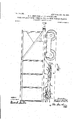
- FIG. 1 is a side elevation of the left-hand half of a railway hopper-wagon fitted with one form of door-operating gearing.
- Fig. 1 isa view similarto Fig. 1 of the right-hand half of the same wagon.
- Fig. 2 is an elevation,on a larger scale,of one door and the gear- Fig. 3 is'a half-plan of the gearing cor- Fig. 4. is a transverse responding to Fig. 2.
- FIGS. 9 are sectional and side-elevations, rcspe'ctively,'of one form of V drum employed.
- Figs. 10 and 11 are side and sectional elevations of a modified form of drum,
- Fig. 12 being a diagrammatic plan illustrating the application of this type of and 14. show, respectively, in elevation and plan a form of ropegrip used when the modified form of drum is employed.
- Figs. 15 and 16 are a sectional e'levation and plan, respectively, of .a modified form'of gearing, and
- Figs, 17 and 18 are similar views of another modified form of. gear-v diagrammatic plan illusdiiferential gear.
- the hop persa b are fitted with doors 0 (1,3d3-Pt9di0 slide longitudinallytoward or away from the center of the wagon.
- the doors are fitted with rollers e, resting on guide-rails f, carried in any suitable manner from the sides of the hoppers or from the vehicle-body.
- the rolling.- Fig. 19 is a ers e are preferablycarried in suitablebearings on channel-irons g,forming the side girders or sills of the doors.
- the doors a d are operated by pairs of wire 'ropes or chain cables h 11,-res'pe'ctiVely, there being two pairs of ropes to each door,one rope on each side.
- the ropes are attached. to the doors by clipping devices,.such as shown in detail in Fig. 6. bolted to thedoors, having These consist of brackets 70,
- V-guides t alter- 45 1ength being passed through an. opening 11 provided for that purpose. tightened up,'whereupon the rope is firmly natinglwith screwed eyelets m on their upper faces.
- the ropes are'led alternately overthe'V- guides and through the eyelets and firmly secured bytightening up the nuts n on theeyelet-bolts.
- the door .0 is secured to the upperpar'ts of the ropes h and the door d to. the lower parts of theropes 'i. 'For t hi s reason 'the brackets 70 on the door are much longer than the brackets It on the door d, the clip-'- ping device shown in Fig. .6 being intended to-grip the upper part of the rope.
- the ropes ht are led around fixed but ad justable guide-pulleysp p and onto winding drums r s, respectively.
- the pulleys pare carried in bearings-2f, supported ;by adjustable bolts w in fixed brackets w, forming stops limiting'the travel of the doors, the bearings being preferablyformed in one or connected by'oross-bars a. By adjusting the bolts w the tension of the ropes may tie-regulated as desired.
- the winding-drums a" s are carried on shafts 2 2, extending transversely .across the wagon, preferably at the'center .thereof, as shown in Figs.
- the drums 1' s are rotated to-open or close .the doors by means of a hand-wheel 12 on a driving-shaft 13, Figs. 2 and 3, a pinion 14,
- -A p'inionsimilar to the pinion 17 is provided on the opposite end-of the central 18 on the shaft 2 of the drums r.
- doors may be independently openedor shut in any desired order, or both'may be opened or shut -nal comprises a knuckle-joint 23,-bol'ted to a bracket 24:,in. turn-bolted to the door.
- the drum is-of split formation, the"meet'- ingedges of the halves 25 being beveled or formed, as shown in Fig. 10, and helicallyarranged, as indicated. at'Figs. 10 and 12.
- a rope is secured at one'end to one terminalon the door, passed over a, guide-pulley,
- FIG. 17 A further modified and simplerforrn of. to winch-gearing isillustrated in Figs. 17 and 18.
- Fig. IS shows the gearing on the near side.
- the drums r 8 preferably of the construction hereinbefore described,are mounted on shafts 2 V 2. These shafts are independ- 15 ently operated from shafts 13 13 through piuions 14 14, gearing directly with wheels 18 18 on said shafts 2 2.
- the shafts 13 extend across the wagon, and each carries a hand-wheel or a star-wheel 12 on each end. 2c.
- the star-wheels may be operated by lengths ,of tubing or other levers in the well-known manner.
- the arms of the'star-wheels project radially and are ou-twardlyinclined, so that though they lie wholly within the vertical plane defining the maximum width of the wagon the lever when in place projectsbeyond such plane describing a conical path 'when the shaft is rotated,the said path bein ⁇ ; clear of the sill of the wagon andof the adjacent star-wheel.
- a The above-described gearing is preferably employed with doors fitted with clips and arranged, as herei'nbefore describedwith reference to Figs. 1 to 6.
- differential gear may be employed, so that as one door is locked or jammed the other door.
- -50 pinion is one element of an ordinary differ it then being found preferable wagon and guide-pulleys at the-other side, the drum' shaftbeingdriv'eu by a transverse.
- drums for operating'the doors the drums may be replaced bysuitably-sprocketed wheels on;- gaging with chains infplace of flexible wire ropes.
- a winding-drum and pulley mounted on the wagon-body upon opposite sides of the door, means for operating the winding-drum, means upon said. drum for gripping the cable after it has been wound thereonsubstantially as described...
- a windingdrum and pulleyuponthe wagon-body on o'ppositesides of the door a cable passing over said drum andpnlley, a. clipping device upon the door .for securing the cable thereto consisting of a bracket secured to the door, ⁇ l-shap'ed projections thereon, screw-eyes alternately arranged between .the projections, the shanks of said eyes passing through the bracket and nuts screwed thereon, the said cable being arranged to pass through the eyes and gripped down intotheirecess of the V-shaped projections by tightening the nuts on the shanks-of the eyes, substantially as described.
- a winding-gear comprising a-flexibleco'nnect'ion and means forclipping said flexible connection to the door comprising arecessed pro- I 30 jection for receiving the flexible connection and a screw-eye throngh.
Landscapes
- Engineering & Computer Science (AREA)
- Transportation (AREA)
- Mechanical Engineering (AREA)
- Power-Operated Mechanisms For Wings (AREA)
Description
PATENTED DEC. 29, 1903. BERROW.
G. H. SHEFFIELD 6: J. D. TWIN DOOR AND APPARATUS THEREFOR FOR USE UPON HOPPER WAGONS.
APPLICATION FILED SEPT. 5, 1903. N0 MODEL. r
10 BHEETS-SHBBT 1.
No. 748,221. PATENTED 1150. 29, 1903. G. H. SHEFFIELD & J. 1). TWINBBRROW'. DOO-R- AND APPARATUS THEREFOR FOR USE UPON HOPPE R WAGONS. APPLICATION FILED SEPT. 5, 1903; Q
I PATENTED DEC. 29, 1903.
W 0 R R E N I W T D L & D L E I F n B H S E G noon AND APPARATUS THEREFOR PU UsE UPON EUPPEE WAGONS;
APPLICATION FILED SEPT. 5, 1
u 4 2 w llfll I0 IODEL.
No. 748,221. P'ATENTEDDEO. 29, 1903. G'. H. SHEFFIELD & J. 1). TWINBERROW. 6 DOORAND APPARATUS THEREFOR FOR USE UPON HOPPER WAGONS.
. APPLICATION PILEDISBPT. a, 1903. no MODEL. 1o sannrssnnnr 4.
I 1" N L I I m o 9Q P g 'i 5 5 L; i. 1
1PM 0 m $3 mm Z Mmm 7% G. H. SHBPPIELDfi: J. D. TWINB DOOR AND APPARATUS THEREFOR FOR USE U APPLICATION FILED SEPT. 5, 1903. N0 MODEL.
Lila. EL
III'II PATENTED DEC. 29, 1903.
' G; H. SHEFFIELD & J. D. TWINBERROW. ADOORAND APPARATUS THEREFOR FOR USE UPON HOPPER WAGONS.
APPLICATION FILED SEPT. 5, 1903. ,H0 MODEL. 10 QHEBTS-SHEET 8.
PATENTED DEC. 29, 1903. G. HLSHEFPIELD & J, D. TWINBBRROW. DOOR AND APPARATUS THEREFOR FOR USE UPON HOPPER WAGONS.
APPLICATION FILED SEPT. 5, 1903.
No. 748,221. v 'PATENTED DEC. 29, 1903'.
G HzSHEFFIELD & J. 1). TWINBBRROW. U DOOR AND APPARATUS THEREFOR FOR USE UPON HOPPER WAGONS.-
APPLIOATION FILED SEPT. 5, 1903.
H0 MODEL. 10 SHEETS-SHEET 8.
Wm 76,6073; 9 97M Jmafj Taxuzberrmm No. 74 ,221. PATBNTED DEG.29,1908.
. e. H. SHEFFIELD & J. 1). TWINBERROW. DOOR AND APPARATUS THEREFOR FOR USE UPON HOPPER WAGONS.
APPLICATION FILED SEPT. 5, 1903.
10 SHEBTSr-SHBET 9.
no MODEL.
6: f7 Jmarj vzs Na.74s;221. I PATENTED D50. 29, 1903.
G. H. SHEFFIELD & J. 1). TWINBERROW..-
DOOR AND APPARATUS THEREFOR FOR USE UPON HOPPEEWAGONS.
. APPLICATION FILED SEPT. 5,- 190a. N0 MODEL. A 1o sums-sum 1o.
12062487 660796; f div 76664 mar z z'za/ozkrraa object being toprovide effective and readily! Toall'w'hom it may concern:
UNITE STATES Patented December 29, 1903.
GEORGE HARR SON SHEFFIELD AND JAMES DENIS JTWINBERRO'W, OF. NEWcAs'rLE-UPoN-TYNE, ENGLAND.
DOOR AND APPARATUS THEREFOR FOR USE UPON HbPPER-WAGONS.
SPECIFICATION forming'pa'rtof Letters Patent No. 7q.s,221 dated December 29, 190s.
'Application' filed September 5, 1903. Serial No. 172,170. (No model.)
Beitknown that we, GEORGE HARRISON SHEFFIELD and JAMES DENIs TWINBERROW,
subjects of the King of Great Britain and Patent in Great Britain,
Ireland, residing at New Bridge street, Newcastle-.upon-Tyne, England, have invented certain new and useful Improvements in Connection with ,Doors and the Apparatus Therefor for Use upon Hopper-Wagons, (for which we have made application for Letters No. 19,446, hearing date September 4, 1902; in India, No. 522 /02, hearing date December 29, 1902, andin Germany, application filed May 23,1903) of which the following isa specification.
This invention relatesto methods of operating and the apparatus employed upon doors for use upon hopper-wagons for railways and the like, more especially in cases wherein the doors are operated'by winding-gear, the
controlled gearing, so arranged that the doors-usually two innu rnber -may be either simultaneously or independently operated, such gearing being alsoarranged for manipulation from either side ofthe wagon.
The invention consists in arranging the gearing for the winding-drums in such manner that the latter may be simultaneously rotated or on' the manipulation of a suitable clutch or clutches drums may be rendered inoperative, so that operation of the gearing simply drives one at twice'its usual speed if the other is jam me'd.
The invention still further consists in special arra ements and constructions of gearing and details connected therewith for 'ef-' fectively operating the doors hereinafter fully described.
Several modesof carrying out the invention lit ing.
'spectively. I Figs. 8 and drum. Figs. 13
tratingthe application of either one or other pair of drums to open or shut the respectiveare illustrated in the accompanying drawings, wherein- Figure 1 is a side elevation of the left-hand half of a railway hopper-wagon fitted with one form of door-operating gearing. Fig. 1 isa view similarto Fig. 1 of the right-hand half of the same wagon. Fig. 2 is an elevation,on a larger scale,of one door and the gear- Fig. 3 is'a half-plan of the gearing cor- Fig. 4. is a transverse responding to Fig. 2.
the lineA B, Fig. 2.
sectional elevation on vFigs. 5 and 5, 6 and 7-are detail views of the and guide-pulley, re-
clutch-levers, rope-clip,
9 are sectional and side-elevations, rcspe'ctively,'of one form of V drum employed. Figs. 10 and 11 are side and sectional elevations of a modified form of drum, Fig. 12 being a diagrammatic plan illustrating the application of this type of and 14. show, respectively, in elevation and plan a form of ropegrip used when the modified form of drum is employed. Figs. 15 and 16 are a sectional e'levation and plan, respectively, of .a modified form'of gearing, and Figs, 17 and 18 are similar views of another modified form of. gear-v diagrammatic plan illusdiiferential gear. In carrying out the invention according to one modification in the application to a doublehopper wagon, as illustrated in Fig. 1, the hop persa b are fitted with doors 0 (1,3d3-Pt9di0 slide longitudinallytoward or away from the center of the wagon. The doors are fitted with rollers e, resting on guide-rails f, carried in any suitable manner from the sides of the hoppers or from the vehicle-body. The rolling.- Fig. 19 is a ers e are preferablycarried in suitablebearings on channel-irons g,forming the side girders or sills of the doors. The doors a d are operated by pairs of wire 'ropes or chain cables h 11,-res'pe'ctiVely, there being two pairs of ropes to each door,one rope on each side. The ropes are attached. to the doors by clipping devices,.such as shown in detail in Fig. 6. bolted to thedoors, having These consist of brackets 70,
V-guides t alter- 45 1ength being passed through an. opening 11 provided for that purpose. tightened up,'whereupon the rope is firmly natinglwith screwed eyelets m on their upper faces. The ropes are'led alternately overthe'V- guides and through the eyelets and firmly secured bytightening up the nuts n on theeyelet-bolts. As explained hereinafter, the door .0 is secured to the upperpar'ts of the ropes h and the door d to. the lower parts of theropes 'i. 'For t hi s reason 'the brackets 70 on the door are much longer than the brackets It on the door d, the clip-'- ping device shown in Fig. .6 being intended to-grip the upper part of the rope.
The ropes ht are led around fixed but ad justable guide-pulleysp p and onto winding drums r s, respectively. The pulleys pare carried in bearings-2f, supported ;by adjustable bolts w in fixed brackets w, forming stops limiting'the travel of the doors, the bearings being preferablyformed in one or connected by'oross-bars a. By adjusting the bolts w the tension of the ropes may tie-regulated as desired. The winding-drums a" s are carried on shafts 2 2, extending transversely .across the wagon, preferably at the'center .thereof, as shown in Figs. 1 to V The'co-nstruction of the drums according to one form will beunderstood on reference to Figs. 8 and 9, wherein one dr um is illustrated, the other drums being identical therewith. 'A disk 3., a drum 4, and a second disk 5 are mounted on the end of the shaft 2, which is provided with ashoulder 6 to resist lateral movement of the disk 3 and is fitted .with a feather or key 7 and a not 8 and yvashe'r on the outer screwed end. The edges of the rim of the drum '4are beveled; and project into re- .cesses 9 10, formed'in thedisks 3 and 5. The
rope 'to'besecured to the'drum is first passed round onc'e,- so as to lie on the beveled-edge opposite, say, the disk.3, once or twice round the drum 4, oif to the door, and round the guide-pulley, back again to the drum, being wound once ortwice about the drum 4, and finally round. the beveledfedge'opposite the other disk 5, the-free end and any excess The nut 8 is then secured between the beveled edges of'the drum 4 and the-disks 3 and 5.=
or words toindicate .in'which direction they should be rotated. in order, to open or closev the doors.
The drums 1' s are rotated to-open or close .the doors by means of a hand-wheel 12 on a driving-shaft 13, Figs. 2 and 3, a pinion 14,
on which gears into a wheel-'15 on a central shaft 16, a second pinion; 17 onwhich ears intoa second 'wheel 18 011" the shaft-2o the.
, shaft 16 to drive a wheelsi milarto the wheel' drum s. -A p'inionsimilar to the pinion 17 is provided on the opposite end-of the central 18 on the shaft 2 of the drums r. r A handfgr "sake: of clearness.
'from either side of Thedisk 5 on allthe drums,or theqdisk-on one drum on each side, may be suitably marked by arrows- :w-heel 12isprovided on as. end oftheshaft 13, the-nearsidejwheel being shown in Fig. 3'and the far-side wheel in Fig- 2,'t'he nearside wheel .being 'omitted in the latter figure If the pinions 17 ere permanently fixed to the. central shaft- 16, both's'ets of drums a" and-'s,"and therefore both do'ors,would be simultaneously operated; but as it is' sometimes desirableto operate the doors independently the'pinions 'are adapted to be secured to the shaft by clutches,
such as shown at'19, Fig. 3. These'elutches are independently manipulated by lovers 2 21, one on each sideof the wagon, but each lever is connected to a free companion lever.
on the opposite side .bya connecting-link 22 in order that either of the clutches maybe manipulated from either side of the wagon.
It willthus be. understood that the doors may be independently openedor shut in any desired order, or both'may be opened or shut -nal comprises a knuckle-joint 23,-bol'ted to a bracket 24:,in. turn-bolted to the door.
The drum is-of split formation, the"meet'- ingedges of the halves 25 being beveled or formed, as shown in Fig. 10, and helicallyarranged, as indicated. at'Figs. 10 and 12.
A rope is secured at one'end to one terminalon the door, passed over a, guide-pulley,
next passed once or twice round one-half of the drum, then passed around and gripped in the helical groove, being securedv therein by a'tightening-nut 2.6. Leaving the grooveat the point 27,,Fig'. 12,-it is again'pa'ssedonce or twice over .the'drum ,-but on the opposite half, and its free end is finally secured bya second terminal on the door. "In a' modified arrangement worm-gearing is substituted for spur-gearing, as-shown in. Figs-15 and 16. Fig. 15 is an irregular sec-, tion, the left-hand half, being a section throughthe 'worm' on the far-side of the" wagon .and the other half, asection through that on the near side.- Fig. 16 shows the gear-' ing on' the near'side, the worm-being omitted for clearness. The 'hand-wheell2 is sea cured to the shaft 13. A bevel-pinion 28 is loose on the shaft, but is. adapted-when required to be securedto [it by a clutch- 19,-s0
'as';.to 'gear'with' andv drivea pinion29 on a worm-shaft 30,,the worm ofwhich 'drives a worm-wheel 31 .on the shaft 2 of the drum 8.
It willthus beseen-thatwhen the wheel 12 operates the drums as the right-hand door is operated. In order to enable the left-hand drum and .door to be operated,.a clutch'1'9- and similar gearing .28 to "31 is provided on trolledfrom either side of the wagon, a 'set of duplicate clutch-levers 21 are provided similar to those already described with reference to Figs. 3, 5, and 5*.
A further modified and simplerforrn of. to winch-gearing isillustrated in Figs. 17 and 18.* Fig. ISshows the gearing on the near side. The drums r 8, preferably of the construction hereinbefore described,are mounted on shafts 2 V 2. These shafts are independ- 15 ently operated from shafts 13 13 through piuions 14 14, gearing directly with wheels 18 18 on said shafts 2 2. The shafts 13 extend across the wagon, and each carries a hand-wheel or a star-wheel 12 on each end. 2c. The star-wheels may be operated by lengths ,of tubing or other levers in the well-known manner.- The arms of the'star-wheels project radially and are ou-twardlyinclined, so that though they lie wholly within the vertical plane defining the maximum width of the wagon the lever when in place projectsbeyond such plane describing a conical path 'when the shaft is rotated,the said path bein}; clear of the sill of the wagon andof the adjacent star-wheel. A The above-described gearing is preferably employed with doors fitted with clips and arranged, as herei'nbefore describedwith reference to Figs. 1 to 6.
differential gear may be employed, so that as one door is locked or jammed the other door.
opened at an increased speed. .In this form i of gearing a single driving-shaft l3 is pro-- vided with a hand-lever 12 on each end. Loose on the shaft are two pinions'l i 14, gearing with wheels 18 18,-keyed on the drumshaftsfl22. Secured to or'i'n one with each ential gear-4n the form shown a bevel-wheel 32-.--the other elements-viz planet-pinions 33-being carried on arms fixed-to the shaft [13. Any other form of equivalent differen- 'tial gear maybe adopted.
It is preferred to use the -above-des'cribed gear with drums, doors, and fittings such as l j hereinbefore described. I i
, The hereinbefore-described methods'of opcrating doors longitudinally of the wagon are equally applicable to the transverse opera+ tion of doors, to place the drum-shaft at one side of the ently' or simultaneously operated, substan- In a still further-modified form of gearing, such as shown diagrammatically in Fig. 19, a
-50 pinion is one element of an ordinary differ it then being found preferable wagon and guide-pulleys at the-other side, the drum' shaftbeingdriv'eu by a transverse.
worm-shaft fitted with suitable time wheels oralevers.
In any of the hereinbefore-described gears, for operating'the doors the drums may be replaced bysuitably-sprocketed wheels on;- gaging with chains infplace of flexible wire ropes.
Having nowdescribed' our invention, what we claim as new, and desire to secure by Letters Patent, is-- 1i In railway andlike double-hopper wagons wherein the doors are operated by flexible winding-gear, twosets of winding-gear, one for each door, adapted to be either independently or simultaneously operated from the samedriving-shaft,= substantially as herein before described.
2. In railway and like double-hopper wagons, the combination of two sets of ,winding-, gear for operatingthe doors, and clutches and leversadapted to be manipulated from either side of the wagon to throw either or both the gears into connection with a driving-shaft whereby the gears may be either independ- 9O tially as hereinbefore described.
- '3. In railway and like double-hopper wag ons wherein the doors are operated by flexible winding-gear two sets of winding-gear one for each door, adapted to be either inde pend'ently or simultaneously operated from the same'fdriving-shaft, and means for operating the said shaft from either side of the wagon substantially as described.
4. In an apparatusfor simultaneously op-' erating two doors of a hopper-wagon, a set ofwinding-gear for each door and a differential gear between the two sets of winding-gear,
substantially as described.
5. In an apparatus for operating the door of 'a hopper-wagon, a winding-drum and pulley mounted on the wagon-body upon opposite sides of the door, means for operating the winding-drum, means upon said. drum for gripping the cable after it has been wound thereonsubstantially as described...
6. In an apparatus for operating the door of a hopper-wagon, a windingdrum and pulleyuponthe wagon-body on o'ppositesides of the door, a cable passing over said drum andpnlley, a. clipping device upon the door .for securing the cable thereto consisting of a bracket secured to the door, \l-shap'ed projections thereon, screw-eyes alternately arranged between .the projections, the shanks of said eyes passing through the bracket and nuts screwed thereon, the said cable being arranged to pass through the eyes and gripped down intotheirecess of the V-shaped projections by tightening the nuts on the shanks-of the eyes, substantially as described.
7. In combination with the wagon,the door,
a winding-gear comprising a-flexibleco'nnect'ion and means forclipping said flexible connection to the door comprising arecessed pro- I 30 jection for receiving the flexible connection and a screw-eye throngh. which the flexible j'usteb'le in relation to the g ecessed projection v 5 and arrangedadjecent thereto, substantially as described.
8."In-combination' with a, hopper-iwagonhaving a door a. cable connected thereto, a,
winding-drum formed insectio'ns andreceiw 'Io'ing the cable betweenfilie'nn, means for ad;
jnsting. the said sections to clamp the cable b'ei'flween them and means for operating. the' drum substantially as describe In Witness whereofwe have he 'eunt'o set our 'hands in the presence of two witnesses. connection passes, said screw-eye being ad.
GEORGE HARRISON SHEFFIELDL JAMES DENIS' TWINBEBROW; Witnesses to the signature 'of the said George Harrison Sheflield: MALOQLM-MCVITTI JOHN JONES BRITTAIN.
-Witnesses to the signature Of the said James Denis Twinberrow:
JOHN SANDEN KIRKPATRICK, LEON PIERARD.
Priority Applications (1)
| Application Number | Priority Date | Filing Date | Title |
|---|---|---|---|
| US17217003A US748221A (en) | 1903-09-05 | 1903-09-05 | Door and apparatus therefor for use upon hopper-wagons. |
Applications Claiming Priority (1)
| Application Number | Priority Date | Filing Date | Title |
|---|---|---|---|
| US17217003A US748221A (en) | 1903-09-05 | 1903-09-05 | Door and apparatus therefor for use upon hopper-wagons. |
Publications (1)
| Publication Number | Publication Date |
|---|---|
| US748221A true US748221A (en) | 1903-12-29 |
Family
ID=2816715
Family Applications (1)
| Application Number | Title | Priority Date | Filing Date |
|---|---|---|---|
| US17217003A Expired - Lifetime US748221A (en) | 1903-09-05 | 1903-09-05 | Door and apparatus therefor for use upon hopper-wagons. |
Country Status (1)
| Country | Link |
|---|---|
| US (1) | US748221A (en) |
Cited By (3)
| Publication number | Priority date | Publication date | Assignee | Title |
|---|---|---|---|---|
| US3446374A (en) * | 1967-01-03 | 1969-05-27 | Pullman Inc | Operating mechanism for vehicle discharge means |
| US3675591A (en) * | 1970-06-01 | 1972-07-11 | Pullman Inc | Chain actuated railway hopper gate |
| US3712249A (en) * | 1970-05-20 | 1973-01-23 | Pullman Inc | Flexible railway hopper closure operating mechanism |
-
1903
- 1903-09-05 US US17217003A patent/US748221A/en not_active Expired - Lifetime
Cited By (3)
| Publication number | Priority date | Publication date | Assignee | Title |
|---|---|---|---|---|
| US3446374A (en) * | 1967-01-03 | 1969-05-27 | Pullman Inc | Operating mechanism for vehicle discharge means |
| US3712249A (en) * | 1970-05-20 | 1973-01-23 | Pullman Inc | Flexible railway hopper closure operating mechanism |
| US3675591A (en) * | 1970-06-01 | 1972-07-11 | Pullman Inc | Chain actuated railway hopper gate |
Similar Documents
| Publication | Publication Date | Title |
|---|---|---|
| US711632A (en) | Hopper-gate and operating mechanism therefor. | |
| US748221A (en) | Door and apparatus therefor for use upon hopper-wagons. | |
| US987877A (en) | Dump-car. | |
| US528279A (en) | Dump-car | |
| DE9404183U1 (en) | Circular or drag circle conveyor | |
| US718742A (en) | Coke-oven lorry. | |
| US719119A (en) | Apparatus for handling stored pulverized or granular materials. | |
| US3540605A (en) | Operating mechanism for vehicle discharge means | |
| US3543691A (en) | Operating mechanism for vehicle discharge means | |
| US914242A (en) | Dump-car. | |
| US833141A (en) | Coal-conveyer. | |
| US726541A (en) | Door-operating gear for coal or coke cars. | |
| US937419A (en) | Dump-car. | |
| US934269A (en) | Drop-door-operating mechanism for hopper-bottom cars. | |
| US665431A (en) | Dumping-car. | |
| US1124188A (en) | Drop-door-operating mechanism for dumping-cars. | |
| US311537A (en) | Traction cable and car | |
| GB190521274A (en) | Improvements in and connected with Railway and like Hopper Wagons. | |
| DE160913C (en) | ||
| US994341A (en) | Dump-car. | |
| US698789A (en) | Car-door mechanism. | |
| US837417A (en) | Side-dump car. | |
| US1087616A (en) | Door-operating mechanism for dump-cars. | |
| DE489428C (en) | Conveyor belt consisting of individual links | |
| US1021866A (en) | Conveying apparatus. |