US7473064B2 - Load indicating fastener insert - Google Patents
Load indicating fastener insert Download PDFInfo
- Publication number
- US7473064B2 US7473064B2 US11/619,100 US61910007A US7473064B2 US 7473064 B2 US7473064 B2 US 7473064B2 US 61910007 A US61910007 A US 61910007A US 7473064 B2 US7473064 B2 US 7473064B2
- Authority
- US
- United States
- Prior art keywords
- load
- washer
- graduated
- gauge
- loading
- Prior art date
- Legal status (The legal status is an assumption and is not a legal conclusion. Google has not performed a legal analysis and makes no representation as to the accuracy of the status listed.)
- Expired - Lifetime
Links
- 230000007246 mechanism Effects 0.000 claims abstract description 72
- 238000000034 method Methods 0.000 claims abstract description 10
- 238000013519 translation Methods 0.000 claims description 2
- 230000000007 visual effect Effects 0.000 description 10
- 238000010276 construction Methods 0.000 description 7
- 230000000875 corresponding effect Effects 0.000 description 5
- 230000004044 response Effects 0.000 description 5
- 230000035899 viability Effects 0.000 description 5
- 238000013461 design Methods 0.000 description 4
- 239000000463 material Substances 0.000 description 4
- 238000011179 visual inspection Methods 0.000 description 4
- 230000008602 contraction Effects 0.000 description 3
- 238000003780 insertion Methods 0.000 description 3
- 125000006850 spacer group Chemical group 0.000 description 3
- 238000006073 displacement reaction Methods 0.000 description 2
- 230000014759 maintenance of location Effects 0.000 description 2
- 238000005259 measurement Methods 0.000 description 2
- 230000002028 premature Effects 0.000 description 2
- 230000000135 prohibitive effect Effects 0.000 description 2
- 238000007789 sealing Methods 0.000 description 2
- 229910000851 Alloy steel Inorganic materials 0.000 description 1
- 102100038946 Proprotein convertase subtilisin/kexin type 6 Human genes 0.000 description 1
- 101710180552 Proprotein convertase subtilisin/kexin type 6 Proteins 0.000 description 1
- 229910000831 Steel Inorganic materials 0.000 description 1
- 238000004026 adhesive bonding Methods 0.000 description 1
- 230000000712 assembly Effects 0.000 description 1
- 238000000429 assembly Methods 0.000 description 1
- 238000004891 communication Methods 0.000 description 1
- 230000006835 compression Effects 0.000 description 1
- 238000007906 compression Methods 0.000 description 1
- 230000001010 compromised effect Effects 0.000 description 1
- 239000012141 concentrate Substances 0.000 description 1
- 230000002596 correlated effect Effects 0.000 description 1
- 230000003247 decreasing effect Effects 0.000 description 1
- 210000005069 ears Anatomy 0.000 description 1
- 230000002401 inhibitory effect Effects 0.000 description 1
- 230000037431 insertion Effects 0.000 description 1
- 230000003993 interaction Effects 0.000 description 1
- 238000004519 manufacturing process Methods 0.000 description 1
- 230000013011 mating Effects 0.000 description 1
- 239000002184 metal Substances 0.000 description 1
- 238000012986 modification Methods 0.000 description 1
- 230000004048 modification Effects 0.000 description 1
- 230000036316 preload Effects 0.000 description 1
- 238000003908 quality control method Methods 0.000 description 1
- 238000005476 soldering Methods 0.000 description 1
- 239000010959 steel Substances 0.000 description 1
- 238000003860 storage Methods 0.000 description 1
- 238000012360 testing method Methods 0.000 description 1
- 238000003466 welding Methods 0.000 description 1
Images


Classifications
-
- F—MECHANICAL ENGINEERING; LIGHTING; HEATING; WEAPONS; BLASTING
- F16—ENGINEERING ELEMENTS AND UNITS; GENERAL MEASURES FOR PRODUCING AND MAINTAINING EFFECTIVE FUNCTIONING OF MACHINES OR INSTALLATIONS; THERMAL INSULATION IN GENERAL
- F16B—DEVICES FOR FASTENING OR SECURING CONSTRUCTIONAL ELEMENTS OR MACHINE PARTS TOGETHER, e.g. NAILS, BOLTS, CIRCLIPS, CLAMPS, CLIPS OR WEDGES; JOINTS OR JOINTING
- F16B31/00—Screwed connections specially modified in view of tensile load; Break-bolts
- F16B31/02—Screwed connections specially modified in view of tensile load; Break-bolts for indicating the attainment of a particular tensile load or limiting tensile load
- F16B31/028—Screwed connections specially modified in view of tensile load; Break-bolts for indicating the attainment of a particular tensile load or limiting tensile load with a load-indicating washer or washer assembly
-
- G—PHYSICS
- G01—MEASURING; TESTING
- G01L—MEASURING FORCE, STRESS, TORQUE, WORK, MECHANICAL POWER, MECHANICAL EFFICIENCY, OR FLUID PRESSURE
- G01L5/00—Apparatus for, or methods of, measuring force, work, mechanical power, or torque, specially adapted for specific purposes
- G01L5/24—Apparatus for, or methods of, measuring force, work, mechanical power, or torque, specially adapted for specific purposes for determining value of torque or twisting moment for tightening a nut or other member which is similarly stressed
- G01L5/243—Apparatus for, or methods of, measuring force, work, mechanical power, or torque, specially adapted for specific purposes for determining value of torque or twisting moment for tightening a nut or other member which is similarly stressed using washers
Definitions
- This invention generally relates to load indicating fasteners, and more particularly, to a load indicating and energy-storing device adapted to visually indicate the load applied by a fastener.
- Fasteners are used in a wide variety of applications, such as motors, railroad tracks, flange assemblies, petrochemical lines, foundations, mills, drag lines, power turbines and studs on cranes and tractors.
- a portion of the fastener e.g. a head of a bolt or the like
- the fastener experiences a strain described as the fastener load.
- this load increases to a maximum break point, where the fastener breaks or its integrity is otherwise compromised. Therefore, it is desirable that applied fasteners should be properly tightened to design load levels in order to ensure that secure joints are achieved without compromising the fastener viability.
- fasteners typically experience a loss of tension, e.g. tightness, due to, for example, a variety of in-service occurrences including: relaxation (thread embedment), vibration loosening, compressive deformation in the joint or flange, temperature expansion or contraction, etc.
- tension e.g. tightness
- the loss of tension that results from these occurrences can cause premature wear in the assembly, leakage (in applications where the fastener is used for sealing), or critical joint failure due to excessively high loads on other members of the assembly.
- Such potential failures are catastrophic in systems where premature wear, leakage or joint failure may result in loss of life.
- An apparatus and method is therefore needed that permits the accurate tightening of a fastener to optimal load levels and that permits the determination of the existing fastener load status.
- tensile strain gives a true representation of the load induced in a fastener.
- Various prior art tensile strain indicators may concentrate on the tensile strain of the individual members of the fastener, such as for example, the fastener washer.
- One such indicator is described in U.S. Pat. No. 6,250,863, issued to Kamentser et al., which purportedly discloses a washer having a plurality of strain gauges integrated into the body of the washer.
- the Kamentser patent discloses two sets of strain gauges, at least one of which is positioned on a portion of the washer subjected to axial force, and at least one of which is positioned on a portion of the washer not subjected to axial force.
- the strain gauges are connected into a common bridge circuit that purportedly provides a signal indicating the axial stress applied to the washer body.
- UK Patent Number GB-2-179-459-A discloses an externally mounted mechanism for indicating the tightness of a fastener.
- This system includes a pin positioned in the bore of the fastener that extends out of the fastener end. Upon extension of the bolt, the pin applies pressure to fulcrumed levers positioned perpendicular to the axis of the bolt. The levers, which are acted upon by a compression spring, are then visible through a window cover for visually inspecting washer load levels.
- the indicator components typically must be positioned on the outside of the bolt. Since the indicator components are rather bulky relative to the washer, the use of the Ceney system is often not possible in fastener environments having space constraints. In cases where it is possible to use such a configuration, the elements of the instrument may be susceptible to outside forces and damage. Upon damage, no convenient method exists to verify whether the unit may still be calibrated.
- a need exist for a load indicating system that conforms to the space limitations of a fastener environment, and that includes means for readily identifying when the load indicator is not valid or the fastener is not at its desired load level.
- one of the main indicators of efficient clamp retention in a joint is the amount of elastic energy the bolt and other joint members can absorb. Regardless of the tightening technique used, when a bolt in a bolted joint is tightened, the bolt stretches elastically and stores energy. In this manner, the bolt acts as a spring and the stored energy facilitates the holding of the joint together at a specified load level.
- fastener designers typically focus on the grip length of the bolt used in the system. It is well known that the longer the grip length of a bolt, the more the energy the bolt will store in the fastener system. Consequently, a longer bolt having a longer grip length, will be able to store more elastic energy than a shorter bolt having a shorter grip length. Thus, the increased grip length of a longer bolt makes using the longer bolt in a fastener more preferable than using the shorter bolt. This is true because, the increased energy stored in the longer bolt is advantageous in that it enhances the integrity of the joint making the joint more tolerable to loosening or failure due to in-service loading.
- the use of the longer bolt is prohibited by space limitations, requiring the system to use a shorter bolt.
- the shorter bolt stores less elastic energy than the longer bolt, which makes the fastener more susceptible to loosening or failure. It is well known, however, that the grip length of the shorter bolt can be made longer, through the use of washers or sleeves that cause the shorter bolt to elastically stretch further and store more energy.
- the bolt's shorter length puts an upper limit on the number of washers that may be used to increase the shorter bolt's grip length.
- This means that, in general, a shorter bolt may only be made to store a limited amount of elastic energy to aid in holding the joint together. Therefore, where, as in many instances, there are space constraints requiring the use of the shorter bolt, a fastening system may be used that results in poorly designed joints, since the shorter bolt may store an inadequate amount of energy.
- This poor grip length bolt diameter-to-length ratio may inevitably lead to joint loosening or failure.
- a fastener system is therefore desired that would allow use of a shorter bolt while not compromising the amount of energy stored in the fastener when a longer bolt is used.
- Such a fastener system may include the storage of additional elastic energy above that already stored in the bolt, and may additionally increase the effective grip length of the shorter bolt improving the fastener clamp retention property.
- the present invention provides a load indicating fastener system that addresses many of the shortcomings of the prior art.
- a load indicating fastener insert is provided that stores elastic energy and that uses a load indicating system allowing visual indication of the load level of the fastener system with relative ease. It should be noted that while the following description is of a load-indicating washer, the present invention is not so limited. That is, any fastener component that indicates fastener load and/or stores energy in accordance with the following description is contemplated to be within the scope of this invention.
- the washer is merely illustrative of any suitable fastener insert or sleeve that may be used as a part of a fastening system.
- the term washer, fastener insert, and joint may be used interchangeably for the purposes of the description and claims provided herein.
- a load indicating system may include a washer configured to store elastic energy during use. Such stored elastic energy may be added to the elastic energy of the fastener bolt thereby increasing the overall stored elastic energy of the fastener system. By increasing the amount of elastic energy in the fastener system, the washer may increase the fastener integrity and minimize the requirement that a longer bolt be used. In particular, the washer may store elastic energy such that the effective grip length of a shorter bolt is increased, allowing use of a shorter bolt in fastening applications where space is limited.
- a washer in accordance with this invention may include an arched surface. The arched surface may be substantially perpendicular to the direction in which a tightening force is applied.
- the arched surface may permit the washer to deflect in the direction of the tightening upon application of an axial load.
- the deflection is described in the downward direction.
- the downward deflection (“dishing”) that occurs permits the washer to act as a spring storing elastic energy.
- the stored elastic energy in the washer may be added to the overall elastic energy of the fastener system, thereby aiding in increased joint integrity.
- the load indicating system uses a removable pin attached in the center of the washer face to drive a load indicating mechanism affixed at opposing ends of the washer front surface.
- the placement of the load indicating mechanism at the opposing ends of the washer front surface is such that the main body of the load indicating mechanism undergoes negligible movement relative to the washer deflection as the washer dishes under load.
- the dishing which is correlative to the amount of the applied axial load, may be measured by the load indicating mechanism system load indicator. The load measurement may then be determined by visual inspection of the load indicator.
- the desired load amounts may be achieved by loading the washer to a corresponding deflection as measured by the load indicator. Once the load is removed, the elastic energy contained in the washer is released and the washer returns to its original unloaded position, wherein the load indicator visually indicates that no load is present.
- the load indicator of the present invention includes a load indicating scale including visual representations of measured axial loading.
- the load indicator may include a load indicating pointer configured to indicate loading of the washer by coming to rest on a visual representation of the load indicating scale during axial loading. The pointer may return to the no load visual representation of the indicator scale once the load is removed.
- the load indicator may additionally include a load set pointer for indicating the initial and/or maximum load level of the load indicating system.
- the load set pointer may be positioned correlative to the load indicating pointer, such that the load set pointer points to the visual representation indicating the maximum axial loading of the load indicating system during use.
- the load set pointer may continue to point out the maximum (or initial) load level experienced by the load indicating system once the axial loading is removed.
- the load set pointer may be used as a set point for the load indicating pointer for indicating the initial loading position of the washer.
- the load set pointer may be driven by the load indicating pointer upon initial loading and remain fixed at the initial loading position, such that when the load indicating flag moves due to washer unloading, relaxation, deformation, expansion, contraction or the like, such movement from the initial loading position can be easily detected upon casual visual inspection.
- the load indicating system may include mechanisms to adjust the zero setting, indicating no axial loading on the load indicating scale and to also adjust the range of the load/deflection response.
- the load indicator system may include an immovable load indicator, comprising an immovably affixed deflection indicator, an adjustable load indicating member positioned within the immovably affixed deflection indicator, and a load indicating feeler gauge.
- the adjustable load indicating member is adjusted to indicate “zero” loading of the washer. Once an axial load is applied, the washer body deflects correlative to the amount of axial loading. The system user may then use the load indicating feeler gauge to determine the amount of axial loading on the washer, by measuring the amount of deflection with respect to the load indicating member.
- the load indicating mechanism is attached to opposite ends of the washer.
- the washer carries a load reference pin that moves relative to the load indicating mechanism during loading and corresponding deflection or dishing of the washer.
- a graduated load gauge attached to the load indicating mechanism is moveable between a disengaged position and an engaged position relative to the load reference pin. Indicia associated with the graduated load gauge indicate the load corresponding to the different degrees of movement required to advance the graduated load gauge into engagement with the load reference pin.
- the graduated load gauge carries a continuously or incrementally graduated surface such as an inclined or stepped ramp.
- the graduated load gauge is a disc carrying an inclined surface at its periphery and is rotatable about an axis substantially parallel to the direction of loading.
- the graduated load gauge is a wedge that is translatable along the load indicating mechanism to engage the reference pin.
- the graduated load gauge may also include a biasing mechanism for returning the graduated load gauge to a disengaged position to prevent damage to either the load reference pin or the graduated load gauge during loading.
- the load reference pin may include a ball bearing to facilitate smoother operation of the graduated load gauge and prevents wear to the load reference pin during engagement with the graduated load gauge.
- the load indicator may include transducers (e.g., displacement or pressure transducer, etc.) capable of being coupled to a portable visual load indicator, for translating the transducer signal into a readable value representing axial load levels.
- transducers e.g., displacement or pressure transducer, etc.
- the axial load on the washer, and the associated washer strain may be detected by the transducer and correlated into an electrical signal readable by the portable visual load indicator, which in turn, gives a visual reading of the amount of axial load present.
- the portable visual load indicator may include an electrical output device or mechanical output device that presents the transducer signal to be read in accordance with the fastener axial load.
- FIG. 1A depicts an exemplary washer in accordance with an exemplary embodiment of the present invention
- FIG. 1B depicts a bottom view of an exemplary washer in accordance with an exemplary embodiment of the present invention
- FIG. 2A depicts another exemplary washer in accordance with an exemplary embodiment of the present invention
- FIG. 2B depicts a first side view of an exemplary washer and seals in accordance with an exemplary embodiment of the present invention
- FIG. 2C depicts a second side view of an exemplary washer in accordance with an exemplary embodiment of the present invention.
- FIG. 2D depicts a bottom view of an exemplary washer in accordance with an exemplary embodiment of the present invention
- FIG. 3A depicts an exemplary embodiment of a load indicating system in accordance with the present invention
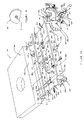
- FIG. 3B depicts an exploded view of an exemplary embodiment of a load indicator mechanism in accordance with the present invention
- FIG. 3C depicts a back view of the load indicating scale in accordance with an exemplary embodiment of the invention.
- FIG. 3D depicts a load indicating pointer assembly in accordance with an exemplary embodiment of the invention
- FIG. 4A depicts another exemplary indicator plate in accordance with an exemplary embodiment of the present invention.
- FIG. 4B depicts an exemplary feeler gauge in accordance with an exemplary embodiment of the present invention
- FIG. 4C depicts another exemplary washer and indicator plate in accordance with an exemplary embodiment of the present invention.
- FIG. 5 depicts another exemplary embodiment in accordance with the present invention, wherein a transducer is used to translate an axial load to a readable electrical signal indicating washer load level;
- FIG. 6A shows an exemplary load/deflection relationship of an exemplary washer in accordance with an exemplary embodiment of the present invention
- FIG. 6B shows another exemplary load/deflection relationship of an exemplary washer in accordance with an exemplary embodiment of the present invention
- FIG. 7A shows a perspective view of an exemplary load indicating mechanism having a rotating graduated load gauge
- FIG. 7B shows a top view of an exemplary load indicating mechanism having a rotating graduated load gauge
- FIG. 7C shows a front view of an exemplary load indicating mechanism having a graduated load gauge
- FIG. 8 shows a front view of an exemplary load indicating mechanism having a sliding graduated load gauge.
- a load indicating system including an insert (e.g. washer) for use with a fastener.
- the washer may be of any configuration for storing elastic energy during axial loading, but preferably, the washer includes at least one arched or recessed surface permitting the washer to dish during loading.
- the arched surface may be convex or concave relative to a geometric plane drawn laterally through the washer body or substantially perpendicular to the direction of the axial loading. As described more fully below, the washer dishes relative to the arched surface causing the washer to store elastic energy during use.
- washer 100 may be substantially rectangular in shape. It should be noted that although the washer 100 is depicted as substantially rectangular, other washer shapes might be suitable for use with the present invention. For example, washer 100 may be oblong, elliptical, polygonal, or any such shape wherein the washer 100 includes a substantially stationary edge, is capable of dishing and/or includes an axial bore for receiving a fastening means (e.g., bolt).
- a fastening means e.g., bolt
- washer 100 may comprise a substantially flat upper surface 104 , a front side surface 108 , a rear side surface 110 , a left side surface 106 and a right side surface 116 , where the aforementioned side surfaces are perpendicular to the flat upper surface 104 .
- Washer 100 further includes a central bore 114 formed axially to the washer 100 centroid for use in inserting a load producing fastener such as a bolt, or screw, or the like (not shown).
- FIG. 1B shows a bottom view of washer 100 , wherein it can be seen that the geometric plane including bottom surface 112 of washer 100 may be drawn substantially parallel to upper surface 104 . That is, bottom surface 112 is configured such that the outer portions 122 of the bottom surface 112 of washer 100 substantially parallel to upper surface 104 . In addition, outer portion 122 may be elevated from the center axis 124 of an arched surface 118 of washer 100 as described more fully below, to provide a surface for containing the surface of the article with which the washer is to be used.
- bottom surface 112 includes a spherical portion 118 , e.g.
- arc 118 is formed such that arc 118 is included in washer bottom surface 112 from washer front side surface 108 to washer rear side surface 110 .
- the arc 118 may be characterized by a radius chosen to ensure that the washer upper surface 104 may deflect downward relative to the axial loading applied at the washer centroid.
- the dimensional characteristics of the washer 100 e.g., washer thickness, length, width, and radius of the arc 118 ) may be chosen such that a desired deflection of the washer 100 may be measured relative to the amount of applied axial loading.
- the desired dimensional characteristics may be chosen in accordance with the amount of desired elastic energy necessary to be stored in the fastener to ensure fastener effectiveness.
- the front surface 108 further includes front bore holes 120 for use in affixing to washer 100 a load indicator mechanism as described more fully below.
- Front bore holes 120 may be any suitable configuration for use in affixing a front load indicator mechanism 350 as shown in FIG. 3A .
- front bore holes 120 may be threaded.
- FIGS. 2A-2C show another exemplary embodiment of a washer 200 in accordance with the present invention.
- washer 200 is substantially rectangular in shape, including a substantially flat upper surface 204 that further includes a central bore 214 formed axially to the washer centroid in substantially the same manner as was described with respect to bore 114 of washer 100 .
- Washer 200 further includes a front surface 226 , rear surface 228 , and side surfaces 222 and 224 each of which may be substantially perpendicular to the upper surface 204 .
- Washer 200 further includes an arched surface 218 of similar description as arc surface 118 of washer 100 .
- washer 200 may be used in any application wherein various circular and/or rectangular seals may be required.
- washer 200 may be configured to accommodate any such seals as are commonly known in the fastener industry.
- a circular seal 250 is required to be fitted around a fastener (e.g., bolt, screw, pin) inserted at central bore 214 .
- Central bore 214 may be formed such that the circular seal 250 containing a central aperture 254 for insertion of the bolt may be inserted or fitted into the upper surface 204 of the washer 200 .
- washer 200 bottom may be configured such that the rectangular seal may be positioned circumspect to the washer bottom portion defined by bottom portion front surface 208 , bottom portion rear surface 240 (shown in FIG. 2D ), and bottom portion side surfaces 206 and 216 .
- the construction and operation of typical seals for use with industrial washers are commonly known and, as such, the seals will not be described herein in detail.
- FIGS. 2A-2C what is shown is an exemplary embodiment of washer 200 formed to accommodate the aforementioned circular and rectangular seals.
- a washer 200 including a circular recess 256 to accommodate a circular seal 250 configured to fit circumferentially around, for example, a bolt-like fastener in the manner described above.
- central bore 214 may include a circular recess 256 centrally positioned to the axis of central bore 214 and configured to receive the circular seal 250 .
- the circular recess 256 may be formed by a circular wall 230 running circumferentially to the axis of central bore 214 and perpendicular to the washer upper surface 204 .
- the diameter of circular wall 230 may be larger than the outer diameter of the circular seal 250 .
- the depth of the circular wall 230 may be such that the circular seal 250 may be inserted into the circular recess 256 wherein it may come to rest on a recess bottom 232 drawn radially to the circular wall 230 . It should be understood then, that when a circular seal 250 is inserted into the circular recess 256 , a fastener such as a bolt may be freely inserted into the central bore 214 opening to protrude out the washer bottom surface 212 , without obstruction where bottom surface 212 may have generally similar description as bottom surface 112 described above.
- a bottom surface 234 of washer 200 may be formed to accept a rectangular seal 252 when required.
- the width and length of bottom surface 234 may be chosen such that the perimeter of the bottom surface 234 is larger than the inner perimeter 258 of the rectangular seal 252 allowing the rectangular seal 252 to be fitted over the bottom surface 234 without inhibiting the use of a fastener such as a bolt.
- FIGS. 2C and 2D another exemplary embodiment of a washer 200 in accordance with the present invention is shown, including serrations 241 on the outer edges of the bottom surface 212 and positioned parallel to arc 218 .
- Such serrations 241 may be included in the washer 200 design, wherein it may be necessary to minimize washer 200 movement during loading of the washer 200 . That is, the serrations 241 are configured to come in contact with a generally immovable surface, such that the serrations render the washer substantially stationary in the direction perpendicular to the serrations during use.
- the immovable surface may, for example, be the article to be fastened.
- washers 100 and 200 may be chosen as required by the particular application in which they are used. For example, the length, width and depth of the washer may be chosen to accommodate space considerations. Furthermore, washers 100 and 200 may be of any material capable of withstanding the load required for a particular application. For example, washers 100 and 200 may be constructed of various steel and steel alloys as required. Moreover, as previously noted, washer dimensions and material considerations may be contemplated to configure larger or smaller washers, or washers using lighter or heavier graded materials, as a particular fastening application may require. Further still, while the exemplary washer embodiment shown in FIGS.
- washer 200 may be configured to accept at least one of the seals or none of the seals as the application requires, and further may be configured with or without the noted serrations.
- a fastener system that measures axial loading is disclosed.
- Such a system may include a mechanism capable of translating the amount of washer dishing into a readable or measurable quantity. That is, the mechanism may translate the dishing into, for example, percent of maximum axial loading, where the maximum axial loading may be the fastener break point.
- the mechanism may translate the amount of dishing into any measurement (e.g. torque) indicative of the axial force applied in tightening the faster system in which the load indicating system of the present invention is used.
- the load indicator mechanism may be mechanical, electrical or a combination thereof as described below.
- FIGS. 3A-3D what is shown is an exemplary embodiment of a load indicating system 300 for use with the present invention, wherein a load indicator mechanism 350 is depicted attached to a washer 301 front surface 303 .
- washer 301 may be of similar construction to washer 200 such that like elements will have similar descriptions as like elements with respect to washer 200 .
- load indicator mechanism 350 is described with respect to washer 301 , the embodiment is not to be so limited.
- load indicator mechanism 350 may be described with respect to washer 100 , 200 or any suitable variations thereof described above, wherein the washer additionally includes a recess of similar description as recess 366 .
- the reference to washer 301 with respect to FIGS. 3A-3C is merely illustrative.
- load indicator mechanism 350 is configured to translate washer deflection to a quantity readable on load indicating scale 312 .
- mechanism 350 may be a multi-gear arrangement. As the washer deflects under axial loading, the gears of mechanism 350 translate the amount of deflection as indicated on scale 312 .
- washer 301 includes a front surface 303 having a hole 366 positioned centrally to washer front surface 303 .
- Load indicator mechanism 350 (shown in FIG. 3 ) includes an inner plate 302 including bore holes 372 , 375 , 391 and 398 , in addition to slotted apertures 314 and 364 , where slotted apertures 314 are positioned at opposing ends of the inner plate 302 and are aligned with bore holes 220 of washer 301 and slotted aperture 364 is positioned centrally to inner plate 302 and is aligned with hole 366 of washer 301 .
- the outside surface of inner plate 302 may also contain generally semi-circular grooves 315 extending longitudinally from the outboard ends of slotted apertures 314 to the ends of inner plate 302 , the purpose of which is explained below.
- load indicator mechanism 350 may also include spacers 317 aligned centrally with bore holes 220 of washer 301 and slotted apertures 314 .
- Load indicator mechanism 350 may further include an outer plate 352 having slotted apertures 336 positioned at opposite ends of the outer plate 352 .
- the position of slotted apertures 336 is such that they align with slotted apertures 314 of inner plated 302 , which, as noted, are further aligned with bore holes of spacers 317 and bore holes 220 of washer 301 .
- both the inner plate 302 and the outer plate 352 of the plate system 350 may be attached to washer 301 using fasteners 330 .
- Fasteners 330 may be any configuration for securing a load indicator mechanism 350 to washer 301 .
- fasteners 330 may be bolts, screws, pins, or the like, or may include any other suitable securing means such as, gluing, soldering, welding or the like.
- fasteners 330 may be, for example, retainer pins 330 that may immovably secure the mechanism inner plate 302 and outer plate 352 to the washer front surface 303 .
- the spacers 317 may be positioned circumspect to fasteners 330
- the inner 302 and outer 352 plates may be positioned onto fasteners 330 through slotted apertures 314 and 336 respectively.
- the fasteners 330 are retainer pins
- the inner 302 and outer 352 plates may be affixed to washer 301 using retainer clips 337 permitting translational movement which is controlled, for example, during quality control testing of the load indicating system 300 .
- Outer plate 352 also includes a slotted aperture 360 , aligned with aperture 364 of inner plate 302 , which is further aligned with threaded hole 366 of washer 301 . Additionally, outer plate 352 includes bore holes 396 and a bore hole 370 respectively aligned with bore holes 398 and bore hole 372 of inner plate 302 .
- the inside surface of outer plate 352 also contains generally semi-circular grooves 318 of similar arrangement as grooves 315 . That is, grooves 318 may extend longitudinally from the outboard ends of slotted apertures 336 to the ends of outer plate 352 . These semi-circular grooves 318 align with semi-circular grooves 315 of inner plate 302 to form longitudinal circular access holes 320 as shown in FIG.
- mechanism 350 may include screws 332 that may be rotated to translationally adjust the load indicator mechanism relative to washer 301 .
- holes 320 provide access for a suitable tool to rotate screws 332 (e.g. screwdriver) for adjusting the load/deflection response of washer 301 , as described below.
- gears Interposed between inner plate 302 and outer plate 352 are a series of gears for translating axial loading into a readable quantity.
- the gears may be defined by a main drive gear 344 , a combination gear 346 , and a pinion gear 348 .
- Main drive gear 344 may include slotted aperture 362 of similar shape as apertures 364 and 360 described above. Slotted aperture 362 may be smaller than apertures 364 and 360 .
- Main drive gear 344 is positioned between the inner plate 302 and the outer plate 352 such that the main gear aperture 362 is aligned with both aperture 364 of inner plate 302 , and with aperture 360 of outer plate 352 , as well as, threaded hole 366 of washer 301 .
- Main drive gear 344 further includes a bore hole 390 that is aligned with bore hole 382 of outer plate 352 and bore hole 391 of inner plate 302 , such that the main drive gear 344 may be held in place and allowed to rotate using a suitable fastener 388 (pivot pin 388 ) such as a screw, pin or the like, where the fastener is positioned through both bore holes 382 , 390 and 391 .
- main drive gear 344 includes a semi-circular recess 392 on lateral edge of gear 344 , which is aligned with bore hole 384 of outer plate 352 .
- a screw 394 including a cam-shaped head, may be rotatably inserted into hole 384 such that the cam-shaped head of screw 394 may be abutted against the semi-circular recess 392 .
- the screw may be threaded into hole 384 or may be inserted into hole 384 and rotatably fastened using a mating nut 386 .
- the screw 394 may then be used to enable the main drive gear to be spring loaded at the zero position on scale 312 when no loading is present. That is, since the cam-shaped (e.g.
- the main drive gear may be rotated by turning screw 394 thereby rotating a load indicating pointer, as described below.
- the load indicating pointer may be adjusted to indicate no axial load (e.g. zero load) prior to use thereby zeroing mechanism 350 .
- any translational movement of the main drive gear 344 relative to the outer plate 352 and inner plate 302 is restricted by pivot pin 388 into bore hole 390 of the main drive gear 344 and bore hole 382 of the outer plate 352 and bore hole 391 of inner plate 302 .
- screw 394 As screw 394 is rotated, its cam-shaped head serves as a zero adjust for the load indicating assembly 356 (shown in FIG. 3D ). After adjustment, the zero adjust screw 394 is immovably secured to outer plate 352 , for example, using a nut 386 .
- a deflection driver 378 Positioned through apertures 360 , 362 , and 364 is a deflection driver 378 that may be securely positioned in hole 366 . As washer 301 is loaded, main drive gear 344 may rotate about pivot pin 388 . The diameter of deflection driver 378 is slightly smaller than the height of aperture 362 providing a sliding fit, to allow rotational and lateral translation of drive gear 344 . For example, main drive gear 344 translates horizontally for adjustment of the load range of the load indicating mechanism 350 , as described below. Deflection driver 378 may be immovably affixed to hole 366 , by any conventional means, but presumably is threaded to mate with threads included in hole 366 .
- the driver 378 may then be screwed into hole 366 such that translational and rotational movement of driver 378 may be minimized or eliminated.
- Pins 330 may be pressed into holes 220 of washer 301 and the load indicator mechanism 350 may be held in place affixed to washer 301 using retaining clips 337 inserted into circumferential grooves 333 of pins 330 .
- Fasteners 330 may be configured with threaded holes 331 for threading or screwing in load/deflection response screws 332 as shown. Holes 331 are threaded laterally through fasteners 330 such that screws 332 may be inserted into holes 331 and through fasteners 330 so that a first end of screws 332 bears against the inside surfaces of apertures 314 .
- Mutual adjustment of screws 332 provides the means to laterally translate main drive gear 344 that may be permanently affixed between inner plate 302 and outer plate 352 with pivot pin 388 , thus varying the pivot length between pin 388 and deflection driver 378 .
- This adjustable pivot length alters the load/deflection response of washer 301 , allowing the load at 100% on scale 312 to be fine tuned and the washer to be calibrated for maximum load on scale 312 prior to use.
- Load indicator mechanism 350 may further include a combination gear 346 including central bore hole aligned with a bore 374 of outer plate 352 and bore hole 375 of inner plate 302 .
- Combination gear 346 is further positioned such that it is interlocked (e.g. meshed) with main drive gear 344 such that the rotation of main drive gear 344 drives rotation of combination gear 346 .
- Combination gear 346 may be held in place by a suitable fastener 376 positioned through the combination gear 346 central bore and through bore holes 374 and 375 , where fastener 376 may be a screw, pin, rivet, or the like.
- Load indicator mechanism 350 includes a pinion gear 348 including a central square bore aligned with a bore 370 of outer plate 352 and a bore 372 of inner plate 302 .
- Pinion gear 348 is further positioned such that it is interlocked with combination gear 346 and is driven (caused to rotate) by it.
- Pinion gear 348 may be held in place by a suitable shaft 354 positioned through the square bore of the pinion gear 348 , where the shaft 354 may be any suitable screw, pin, rivet or the like, including a first square end 355 configured to tightly fit within the square bore, such that rotation of pinion gear 348 causes rotation of the shaft 354 .
- Load indicator mechanism 350 further includes a load indicating scale 312 with a central bore 369 that may be aligned with bore 370 of outer plate 352 .
- Load indicating scale 312 includes markings as shown (e.g., 0%, 25%, 50%, 75%, and 100%), for indicating a measurable axial loading of washer 301 .
- load indicating scale 312 is configured to have a protruding boss 313 that may be located on the scale 312 back side (shown in FIG. 3C ).
- the boss 313 may align with hole 370 of outer plate 352 .
- the outer diameter of boss 313 may be configured such that the scale 312 of load indicator assembly 356 (described below) may be affixed to outer plate 352 by, for example, press fitting the boss 313 into hole 370 .
- load indicator mechanism 350 may include a load indicator assembly 356 as shown in FIG. 3D .
- the assembly 356 may include a load indicating pointer system such as, for example, the arrangement given by flag 308 , flag retainer 309 , fasteners 310 and nuts 311 .
- Load indicator assembly 356 may also contain a load set pointer 307 for indication of initial washer loading or target loading. Both the load indicating pointer system and the load set pointer 307 indicate to a user the axial loading on washer 301 by pointing to a load indicating marking on scale 312 .
- the load indicating pointer and load set pointer 307 may be any construction useful for indicating to the user the appropriate axial load placed on washer 301 , such as those depicted in FIG. 3B .
- flag retainer 309 of the load indicating pointer system may be of sheet metal construction formed circumspect to shaft 354 .
- the retainer 309 may be formed to securely hold shaft 354 and flag 308 such that flag 308 rotates correlative to the rotation of shaft 354 .
- the flag retainer 309 may be formed with bore holes 325 that may be aligned with bore holes 326 of flag 308 .
- Flag 308 contains bore holes 326 that align with flag retainer bore holes 325 when flag 308 is inserted between the ears of flag retainer 309 .
- Flag 308 may be affixed to retainer 309 and the assembly may be affixed to the outer end of shaft 354 with fasteners 310 inserted into bore holes 326 of flag 308 and bore holes 325 of flag retainer 309 .
- fasteners 310 may include nuts 311 affixed to fasteners 310 for securing flag 308 and retainer 309 to shaft 354 .
- Shaft 354 is inserted into the bore hole of pointer 307 and the bore hole 364 369 of scale 312 , making up the load indicating assembly 356 shown in FIG. 3D .
- the outer-most diameter of shaft 354 may be configured to be slightly smaller than the bore of pointer 307 so as to fit rotationally snug within it.
- the diameter of bore hole 369 of scale 312 is larger than the outer-most diameter of shaft 354 so that shaft 354 rotates freely within it.
- the square end 355 of shaft 354 is configured to fit immovably into the square hole of pinion gear 348 and the outer diameter 357 of shaft 354 is configured to fit snugly into the round hole 372 of inner plate 302 and is free to rotate within it. With this arrangement, flag 308 and pointer 307 may rotate relative to scale 312 as pinion gear 348 rotates.
- flag retainer 309 may be configured with an extension 321 that abuts against load set pointer 307 allowing pointer 307 to be driven by primary flag 308 during loading, for providing an attained maximum load indication. That is, as the washer 301 is loaded, the mechanism 350 gears 344 , 346 , 348 rotate causing shaft 354 and flag 308 to correlatively rotate. As the flag 308 rotates, flag retainer 309 rotates ensuring abutment of extension 321 against load set pointer 370 . As the flag 308 comes to rest following loading of washer 301 , both the flag 308 and load set pointer 307 indicate an axial loading quantity on scale 312 .
- pointer 371 307 moves with the movement of flag 308 .
- pointer 307 remains fixed at the maximum axial loading experienced by the washer 301 .
- end of pointer 307 may be bent over against the top edge of scale 312 providing enough friction to remain in position yet still rotate manually as described below.
- Load set pointer 307 of load indicator mechanism 350 may be manually rotated about shaft 354 to serve as a target loading point (e.g. set point) for which to align flag 308 during initial loading or subsequent loading of the washer 301 .
- target loading point e.g. set point
- deflection driver 378 may be removed from bore hole 366 of washer 301 , either under load or with no load on washer 301 , to check the movement of load indicator mechanism 350 . With no load on washer 301 , deflection driver 378 may be removed from hole 366 , after which flag 308 should rest at the zero load marking on scale 312 . By rotating flag 308 from zero to 100% and noting a smooth rotation of the flag 308 and pointer 371 the integrity of the working mechanism 350 may be examined. Upon re-insertion of deflection driver 378 into hole 366 when no axial load is present, flag 308 and pointer 307 returns to zero marking on load scale 312 indicating a no load condition.
- deflection driver 378 may be removed from hole 366 in the same manner as above with load on washer 301 . In this case, flag 308 and pointer 307 should return to zero marking assuring the integrity of the working mechanism 350 . Furthermore, with re-insertion of load driver 378 into hole 366 , flag 308 and pointer 307 should return to the previous indicated load on scale 312 .
- deflection driver 378 might be chosen such that the end of driver 378 is movably fitted into hole 366 .
- main drive gear is put in tacit communication with washer 301 , such that the main drive gear 344 rotates as washer 301 dishes under axial loading of the washer 301 .
- the movement of main drive gear 344 drives combination gear 346 , which, in turn, drives pinion gear 348 .
- pinion gear 348 With noted, the movement of pinion gear 348 with its square bore causes shaft 354 to rotate, which, in turn positions pointer 307 and flag 308 along the scale 312 correlative to the amount of axial loading on washer 301 .
- a spring 306 may be used to ensure that the interlocking of the gears 344 , 346 and 348 remains snug during movement to minimize the backlash.
- spring 306 may be positioned between inner plate 302 and outer plate 352 using suitable fasteners such as pins 338 , where pins 338 are fitted in bore holes 398 of inner plate 302 and 396 of outer plate 352 , as shown.
- Spring 306 may further be attached to the end of main drive gear 344 near semi-circular opening 392 such that the elastic energy stored in spring 306 causes main drive gear 344 to exert rotational pressure on combination gear 346 , which, in turn, causes combination gear 346 to exert rotational pressure on pinion gear 348 . It should be understood, that in this configuration, the elastic energy stored in spring 306 will be sufficient to force the gears 344 , 346 , and 348 to rotate to the zero stop setting so as to preload the gearing and inhibit backlash.
- combination gear 346 may be chosen with respect to the expected dishing in washer 301 , such that the gear ratio as measured from the main drive gear 344 to pinion gear 348 is sufficient to ensure ample movement of pointer 310 during operation of the load indicating system 300 .
- combination gear 346 is depicted having a small gear ratio between main drive gear 344 and combination gear 346 , such that a small dishing experienced by washer 301 will translate into a larger rotation of pinion gear 348 , since combination gear 346 is constructed with a smaller gear arrangement at gear 346 abutment with main drive gear 346 and a large gear arrangement at the abutment of gear 346 with pinion gear 348 .
- This will allow a small dishing of washer 301 to be translated into a measurable axial loading quantity at flag 308 .
- Such gear structures are commonly known. As such, the operation of combination gear 346 will not be discussed herein in detail.
- FIG. 4A depicts another exemplary embodiment of a load indicating system 400 in accordance with the present invention.
- Load indicating system 400 is described with respect to washer 200 , although it should be understood that the system 400 may be described with respect to any variation of the washers described herein.
- load indicating system 400 may include a load indicating plate 402 and a deflection indicator 420 .
- Load indicating plate 402 may further include bore holes 410 at opposing ends of the indicator plate 402 for accepting a fastener for affixing the indicator plate to a washer (not shown).
- Deflection indicator 420 may be immovably affixed to indicator plate 402 , or may be formed as a projection emanating from the indicator plate 402 body as shown.
- deflection indicator 420 may comprise an adjustable member, such as, for example, a screw 408 inserted in the deflection indicator 420 such that the screw may be positioned perpendicularly to the surface 204 of a washer in accordance with the present invention.
- deflection indicator 420 may include an opening 412 suitably configured to allow visual and physical access to the gap between the end of screw 408 and washer surface 204 .
- FIG. 4B depicts an exemplary feeler gauge 430 in accordance with the present invention.
- feeler gauge 430 may include feeler tabs 432 , 434 , 436 , 438 and 440 of varying thickness, where each level of thickness corresponds to the measure of deflection, e.g., the load, experienced by a washer 200 .
- the width of feeler tabs 432 , 434 , 436 , 438 and 440 are such that each tab may be inserted into opening 412 during operation of the load indicating mechanism system 450 (shown in FIG. 4C ).
- each feeler tab may be employed to indicate the percentage of deflection experienced by the washer 200 , as shown, where 0% indicates that the washer 200 is experiencing no axial loading and 100% indicates that the washer 200 is at its critical effective loading level (e.g., proof load or breaking point or loss of integrity).
- critical effective loading level e.g., proof load or breaking point or loss of integrity
- feeler gauge 430 uses a percent correlation to axial loading as a gauge reading, the invention is not to be so limited.
- the feeler gauge 430 of the present invention may use load indicating numbers that visually provide the actual loading presently being experienced by the washer load indicating system 450 , or any such similar indication of load.
- feeler gauge 430 is depicted with five feeler tabs, it should be understood that the invention is not to be so limited.
- feeler gauge 430 may include more feeler tabs, such as when it may be necessary to provide axial loading to the washer 200 in more graduated levels.
- the feeler tabs may be configured to indicate axial loading of 10%, 20%, 30%, 40%, 50%, 60%, 70%, 80%, 90% and 100% as required.
- feeler gauge 430 may include fewer feeler tabs, such as when it may be necessary to determine the axial loading of the feeler tabs at less graduated levels.
- feeler gauge 430 may include four feeler tabs, where the feeler tabs may be used to indicate an axial loading of 0%, 33%, 66%, and 99%.
- 0% may indicate no axial loading of the washer 100
- 200 and 99% may indicate that the washer 200 has reached its critical effective loading level (e.g., proof load or breaking point or loss of integrity).
- the operation of the load indicating system 450 may be understood more fully with reference to FIG. 4C , where the system comprises the load indicating mechanism 400 shown affixed to a washer 200 . As shown, bore holes 410 of the load indicating mechanism 400 are positioned against bore holes 220 of washer 200 such that suitable fasteners 407 may be employed to immovably affix the load indicating mechanism 400 to the washer 200 front side surface 226 . It should be understood that indicator plate 402 of load indicating mechanism 400 may be attached to the suitable washer 200 using any such fastening method capable of holding the indicator plate 402 immobile with respect to the washer 200 front side surface 226 .
- Indicator mechanism 400 is affixed such that the adjustable screw 408 is positioned along the centerline 451 of the washer top surface 204 . That is, adjustable screw 408 is positioned such that it is substantially equidistant between the left side surface 222 and right side surface 224 .
- feeler tab 432 of feeler gauge 430 may be placed into opening 412 , and more particularly, under the bottom portion of adjustable screw 408 and onto the surface of washer 200 . The adjustable screw 408 may then be adjusted so that it comes to rest on top of feeler tab 432 , which, in turn, allows calibration of the load indicating mechanism 400 at zero load condition.
- a measurable gap is created between the adjustable screw 408 and the washer upper surface 204 and the deflection indicator 420 is calibrated such that the feeler tab 432 when inserted into the measurable gap as described above, indicates that the washer 200 is experiencing 0% load.
- the washer 200 experiences a deflection correlative to the amount of loading on the system. This deflection, in turn, causes the washer 200 to store elastic energy and further causes the measurable gap to increase or decrease in accordance with the amount of axial load.
- the amount of desired increase or decrease in axial load can then be accurately determined using feeler tabs 434 , 436 , 438 , 440 in similar manner as was described above with respect to feeler tab 432 . More particularly, the axial load may then be increased or decreased to a desired load as measured by the feeler tabs of feeler gauge 430 .
- the axial load may be increased on washer 200 until feeler tab 436 fits into opening 412 such that adjustable screw 408 rest on the surface of the feeler tab 436 , and the feeler tab 436 rests on the washer 200 upper surface 204 .
- 100% load may be measured by inserting feeler tab 440 in like manner as was done with respect to feeler tab 436 .
- feeler tab 440 may represent the critical effective loading level of the washer.
- 100% load may represent any load desired by the system user.
- another exemplary load indicating system 700 comprises a washer 702 carrying a load indicating mechanism 704 attached to opposite ends of washer 702 .
- Washer 702 also carries a load reference pin 706 substantially aligned with the portion of washer 702 that experiences dishing during loading of washer 702 .
- Load reference pin 706 may be formed as part of washer 702 or may be attached thereto and may be a pin, post, ledge, ridge or other reference suitable as an engageable reference for graduated load gauge 708 .
- Load indicating mechanism 704 carries a graduated load gauge 708 configured to be moveable between a disengaged position and an engaged position relative to load reference pin 706 .
- Graduated load gauge 708 may include indicia corresponding to the different degrees of movement required to advance graduated load gauge 708 into engagement with load reference pin 706 .
- Graduated load gauge 708 includes a continuously graduated surface such as an inclined ramp or incrementally graduated surfaces such as a stepped ramp.
- Graduated load gauge 708 may include any suitable load indicia described herein.
- Graduated load gauge 708 is a disc carrying an inclined surface or rim at its periphery and is rotatable about an axis substantially parallel to the direction of loading and substantially aligned with the load reference pin 706 .
- graduated load gauge 708 is positioned with reference to load indicating mechanism 704 while load reference pin 706 is positioned with reference to washer 702 such that the variation in a gap measurable between graduated load gauge 708 and load reference pin 706 is indicative of the dishing of washer 702 .
- Graduated load gauge 708 may also, include a biasing mechanism for returning graduated load gauge 708 to a disengaged position to prevent damage to either load reference pin 706 or graduated load gauge 708 during loading.
- graduated load gauge 708 may be translatable along its rotational axis between a disengaged position and an operable position. To determine the loading experienced by washer 702 , graduated load gauge 708 is first translated into the operable position adjacent load reference pin 706 is then rotated until it engages load reference pin 706 . The degree of rotation required to engage load reference pin 706 corresponds to the degree of dishing of washer 702 due to loading by a fastener. One or more springs may be used to bias graduated load gauge 708 towards the disengaged position.
- a spring may serve to translate graduated load gauge 708 along its axis to a disengaged position, or to rotate graduated load gauge 708 about its axis to a disengaged position, or both.
- a single spring may exert both axial and rotational biasing forces to return graduated load gauge 708 to both a zero load position and a disengaged position.
- Load reference pin 706 may include a ball bearing about load reference pin 706 and engageable by graduated load gauge 708 to facilitate smoother interaction with graduated load gauge 708 and to prevent wear to load reference pin 706 during operation of graduated load gauge 708 .
- Any suitable sensor may be associated with graduated load gauge 708 to detect rotation of the graduate load gauge and to display the varying degrees of loading corresponding to the detected rotation.
- graduated load gauge 708 is perpendicular to the direction of loading to engage reference pin 706
- one of load indicating mechanism 704 and graduated load gauge 708 may be configured with a slot 510 formed perpendicular to the direction of loading and the other of load indicating mechanism 704 and graduated load gauge 708 is configured with a feature to slideably engage slot 510 so that graduated load gauge 708 may translate with reference to load reference pin 706 .
- Any configuration suitable to allow movement of graduated load gauge 708 to engage load reference pin 706 may be used in accordance with the present invention.
- a load indicator system 500 may incorporate a transducer 504 capable of detecting the deflection of a washer 502 may be used.
- a suitable transducer for use with this embodiment may be a LVDT or SPC4 displacement transducer, or the like, as is commonly known.
- load indicating system 500 may be of similar construction and operation as washer system 400 described with respect to FIGS. 4A-4C .
- system 500 uses a deflection transducer capable of converting the washer 502 deflection into a signal readable by an externally situated visually friendly component.
- the component may be a display device capable of translating the signal from the transducer into a quantity discernable through visual inspection, where the quantity is a representation of washer dishing and/or axial loading.
- the washer 502 deflection may converted into an electrical signal representative of the total deflection experienced by the system 700 , and or the percent deflection relative to some known quantity (e.g., washer break point).
- An electrical component, such as a display device 505 may receive the signal through a cable 506 , wherein the signal may be converted to an electrical output correlative to the loading experienced by the system 500 , that is readable by the system 500 user. It should be noted, that while system 500 is described with respect to an electrical output, the invention is not to be so limited.
- the transducer 504 may convert the detected deflection into a signal that may be sent to any suitable output device for displaying the deflection in a form readable by the system 700 user.
- component 505 may be mechanical.
- component 505 may be removable from cable 506 , such that the component 505 may be employed (e.g., reattached to cable 506 ) when examining the load condition of the washer 502 .
- the spherical bottom portion 118 and 218 of washer 100 and 200 deflects proportionately to the applied load, which, in turn, causes the upper surface of the washer 100 and 200 to deflect correlatively and further causes the washer to store elastic energy.
- the dimensional features of the washer may be controlled so that at a certain deflection of the spherical surface 118 and 218 , a desired load condition can be achieved increasing the viability of a fastener arrangement.
- the washer 200 may be designed so that the maximum load, e.g., 100% load, represents the proof load of the fastener used to apply the axial load to the washer 200 .
- the maximum load e.g., 100% load
- the spherical surface 218 may typically be configured such that a deflection of 0.060 inches is measured in the washer 200 at 80,000 lbs.
- This elastic energy given to the washer deflection may be added to the elastic energy stored in the typical joint arrangement not using such a washer 200 , which may ordinarily experience a deflection of 0.006 inches.
- the joint will experience a total deflection of 0.066 inches, since the energy given to the deflection of the washer 200 may now be added to the elastic energy stored in the bolt.
- a 1000% increase in stored elastic energy is evident, which increases the viability of the joint. That is, the joint becomes 10 times more tolerant to in-service loosing or failure.
- FIG. 6B what is shown is an exemplary load-deflection relationship of a typical joint using a 5 inch by 5.7 inch washer 200 with a 90,000 lbs. capacity and a 11 ⁇ 2 inch bolt at a 4 inch grip length.
- the spherical surface 218 may typically be configured such that a deflection of 0.030′′ is measured in the washer 200 at 90,000 lbs.
- This elastic energy given to the washer 200 deflection may be added to the elastic energy stored in the typical joint arrangement not using such a washer 200 , which may ordinarily experience a deflection of 0.007 inches.
- central bore of the washers described above may be configured to accommodate any apparatus for fastening or sealing. That is, where a rectangular seal is to be inserted into the central bore location, the washer recess may be configured to accommodate such rectangular seal. Similarly, where a circular seal is to be used with respect to the bottom surface of the washer the bottom surface may be configured such that the circular seal may be inserted around the perimeter of the bottom surface. In the alternative, the washer may be configured such that only one seal or no seals are use. Further, the washer bottom may be formed with or without the use of serrations as required.
Landscapes
- Engineering & Computer Science (AREA)
- General Engineering & Computer Science (AREA)
- Physics & Mathematics (AREA)
- General Physics & Mathematics (AREA)
- Mechanical Engineering (AREA)
- Bolts, Nuts, And Washers (AREA)
Abstract
Description
Claims (17)
Priority Applications (1)
| Application Number | Priority Date | Filing Date | Title |
|---|---|---|---|
| US11/619,100 US7473064B2 (en) | 2001-11-16 | 2007-01-02 | Load indicating fastener insert |
Applications Claiming Priority (3)
| Application Number | Priority Date | Filing Date | Title |
|---|---|---|---|
| US09/992,871 US20030095848A1 (en) | 2001-11-16 | 2001-11-16 | Load indicating fastener insert |
| US10/401,439 US7156595B2 (en) | 2001-11-16 | 2003-03-27 | Load indicating fastener insert |
| US11/619,100 US7473064B2 (en) | 2001-11-16 | 2007-01-02 | Load indicating fastener insert |
Related Parent Applications (1)
| Application Number | Title | Priority Date | Filing Date |
|---|---|---|---|
| US10/401,439 Continuation-In-Part US7156595B2 (en) | 2001-11-16 | 2003-03-27 | Load indicating fastener insert |
Publications (2)
| Publication Number | Publication Date |
|---|---|
| US20070243034A1 US20070243034A1 (en) | 2007-10-18 |
| US7473064B2 true US7473064B2 (en) | 2009-01-06 |
Family
ID=38604980
Family Applications (1)
| Application Number | Title | Priority Date | Filing Date |
|---|---|---|---|
| US11/619,100 Expired - Lifetime US7473064B2 (en) | 2001-11-16 | 2007-01-02 | Load indicating fastener insert |
Country Status (1)
| Country | Link |
|---|---|
| US (1) | US7473064B2 (en) |
Families Citing this family (1)
| Publication number | Priority date | Publication date | Assignee | Title |
|---|---|---|---|---|
| DE102012005614B4 (en) * | 2012-03-22 | 2013-10-17 | Matthias Brenneis | Sensory connection element and manufacturing method |
Citations (7)
| Publication number | Priority date | Publication date | Assignee | Title |
|---|---|---|---|---|
| US1019097A (en) * | 1911-12-12 | 1912-03-05 | Frank E Spencer | Nut-lock. |
| US3169440A (en) * | 1960-09-09 | 1965-02-16 | Anglo Transvaal Cons Invest Co | Tension indicating devices for instance in roof bolting |
| US3329058A (en) * | 1964-04-14 | 1967-07-04 | Cumming James Deans | Tension indicating washer |
| US4131050A (en) * | 1977-07-05 | 1978-12-26 | The Solon Manufacturing Company | Visual load indicator |
| US4149446A (en) * | 1977-12-01 | 1979-04-17 | Bethlehem Steel Corporation | Load indicator washer |
| US4293257A (en) * | 1980-03-17 | 1981-10-06 | Illinois Tool Works Inc. | Tension indicating washer |
| US6244804B1 (en) * | 1998-09-25 | 2001-06-12 | Malcolm H. Hodge | Tension-indicating fasteners |
-
2007
- 2007-01-02 US US11/619,100 patent/US7473064B2/en not_active Expired - Lifetime
Patent Citations (7)
| Publication number | Priority date | Publication date | Assignee | Title |
|---|---|---|---|---|
| US1019097A (en) * | 1911-12-12 | 1912-03-05 | Frank E Spencer | Nut-lock. |
| US3169440A (en) * | 1960-09-09 | 1965-02-16 | Anglo Transvaal Cons Invest Co | Tension indicating devices for instance in roof bolting |
| US3329058A (en) * | 1964-04-14 | 1967-07-04 | Cumming James Deans | Tension indicating washer |
| US4131050A (en) * | 1977-07-05 | 1978-12-26 | The Solon Manufacturing Company | Visual load indicator |
| US4149446A (en) * | 1977-12-01 | 1979-04-17 | Bethlehem Steel Corporation | Load indicator washer |
| US4293257A (en) * | 1980-03-17 | 1981-10-06 | Illinois Tool Works Inc. | Tension indicating washer |
| US6244804B1 (en) * | 1998-09-25 | 2001-06-12 | Malcolm H. Hodge | Tension-indicating fasteners |
Also Published As
| Publication number | Publication date |
|---|---|
| US20070243034A1 (en) | 2007-10-18 |
Similar Documents
| Publication | Publication Date | Title |
|---|---|---|
| CN101622462B (en) | Method and device for indicating load | |
| CA1311944C (en) | Apparatus and method for monitoring bolt tension in situ | |
| US3943819A (en) | Tensile member with tension indicating means | |
| US6204771B1 (en) | Load indicating fastener systems method and apparatus | |
| US3285120A (en) | Preload bolt joint | |
| US5339696A (en) | Bolt torque and tension transducer | |
| EP0491035B1 (en) | Apparatus for measuring valve stem loads in a motor operated valve assembly | |
| US20090301383A1 (en) | Indicating fastener loading | |
| US3329058A (en) | Tension indicating washer | |
| US5668323A (en) | Method and apparatus for indicating a load | |
| NO323064B1 (en) | Device for painting biasing force in a bolt-nut connection | |
| US10808746B2 (en) | Load indicating fastener | |
| US10436657B2 (en) | Method for determining an axial tensile force applied to a component | |
| US4282762A (en) | Load sensing transducer | |
| US7156595B2 (en) | Load indicating fastener insert | |
| US4090399A (en) | Load measuring gage | |
| US3212325A (en) | Force measuring instrument | |
| US7473064B2 (en) | Load indicating fastener insert | |
| EP3483577B1 (en) | System and method for determining tension of a non-living object | |
| US20030095848A1 (en) | Load indicating fastener insert | |
| JPH0228266Y2 (en) | ||
| GB2050624A (en) | Strain transducers | |
| JP2004093377A (en) | Bolt axial force measuring device | |
| JPH0228267Y2 (en) | ||
| Ramhormozian et al. | A rotation-based method for bolt and Belleville Spring preloading for seismic friction sliding structural connections |
Legal Events
| Date | Code | Title | Description |
|---|---|---|---|
| AS | Assignment |
Owner name: VALLEY FORGE & BOLT MANUFACTURING COMPANY, ARIZONA Free format text: ASSIGNMENT OF ASSIGNORS INTEREST;ASSIGNOR:CLARKE, RONALD C.;REEL/FRAME:019524/0926 Effective date: 20070423 |
|
| AS | Assignment |
Owner name: CLARKE, PHILOMENA, ARIZONA Free format text: CORRECTIVE ASSIGNMENT TO CORRECT THE ASSIGNEES NAMES. DOCUMENT PREVIOUSLY RECORDED AT REEL 019524 FRAME 0926;ASSIGNOR:CLARKE, RONALD;REEL/FRAME:020000/0190 Effective date: 20070423 Owner name: CLARKE, RONALD C., ARIZONA Free format text: CORRECTIVE ASSIGNMENT TO CORRECT THE ASSIGNEES NAMES. DOCUMENT PREVIOUSLY RECORDED AT REEL 019524 FRAME 0926;ASSIGNOR:CLARKE, RONALD;REEL/FRAME:020000/0190 Effective date: 20070423 |
|
| STCF | Information on status: patent grant |
Free format text: PATENTED CASE |
|
| FPAY | Fee payment |
Year of fee payment: 4 |
|
| FEPP | Fee payment procedure |
Free format text: PAYOR NUMBER ASSIGNED (ORIGINAL EVENT CODE: ASPN); ENTITY STATUS OF PATENT OWNER: SMALL ENTITY |
|
| FPAY | Fee payment |
Year of fee payment: 8 |
|
| MAFP | Maintenance fee payment |
Free format text: PAYMENT OF MAINTENANCE FEE, 12TH YR, SMALL ENTITY (ORIGINAL EVENT CODE: M2553); ENTITY STATUS OF PATENT OWNER: SMALL ENTITY Year of fee payment: 12 |
|
| AS | Assignment |
Owner name: VALLEY FORGE & BOLT MFG. CO., ARIZONA Free format text: ASSIGNMENT OF ASSIGNORS INTEREST;ASSIGNOR:CLARKE, RONALD C.;REEL/FRAME:059260/0889 Effective date: 20211001 |