US7448710B2 - Liquid droplet ejection head and image forming apparatus - Google Patents
Liquid droplet ejection head and image forming apparatus Download PDFInfo
- Publication number
- US7448710B2 US7448710B2 US11/180,704 US18070405A US7448710B2 US 7448710 B2 US7448710 B2 US 7448710B2 US 18070405 A US18070405 A US 18070405A US 7448710 B2 US7448710 B2 US 7448710B2
- Authority
- US
- United States
- Prior art keywords
- liquid
- nozzles
- nozzle
- ejection
- ejected
- Prior art date
- Legal status (The legal status is an assumption and is not a legal conclusion. Google has not performed a legal analysis and makes no representation as to the accuracy of the status listed.)
- Expired - Fee Related, expires
Links
- 239000007788 liquid Substances 0.000 title claims abstract description 458
- 238000003825 pressing Methods 0.000 claims abstract description 6
- 239000000203 mixture Substances 0.000 claims description 45
- 238000006243 chemical reaction Methods 0.000 claims description 28
- 239000000463 material Substances 0.000 claims description 23
- 238000004040 coloring Methods 0.000 claims description 20
- 239000003795 chemical substances by application Substances 0.000 claims description 17
- 230000001737 promoting effect Effects 0.000 claims description 17
- 239000003340 retarding agent Substances 0.000 claims description 7
- 238000011144 upstream manufacturing Methods 0.000 claims description 6
- 238000002156 mixing Methods 0.000 claims description 3
- 239000000976 ink Substances 0.000 description 94
- 238000010586 diagram Methods 0.000 description 28
- 238000007639 printing Methods 0.000 description 20
- 238000000034 method Methods 0.000 description 18
- 238000004140 cleaning Methods 0.000 description 17
- 239000003086 colorant Substances 0.000 description 15
- 238000011068 loading method Methods 0.000 description 13
- 230000007246 mechanism Effects 0.000 description 12
- 238000004891 communication Methods 0.000 description 9
- 238000012545 processing Methods 0.000 description 9
- 230000009471 action Effects 0.000 description 8
- 238000010438 heat treatment Methods 0.000 description 7
- 239000011159 matrix material Substances 0.000 description 7
- 238000012360 testing method Methods 0.000 description 7
- 230000000740 bleeding effect Effects 0.000 description 6
- 238000001035 drying Methods 0.000 description 5
- 230000006870 function Effects 0.000 description 5
- 230000001276 controlling effect Effects 0.000 description 4
- 230000037361 pathway Effects 0.000 description 4
- 239000007921 spray Substances 0.000 description 4
- 238000003860 storage Methods 0.000 description 4
- 230000015572 biosynthetic process Effects 0.000 description 3
- 230000008021 deposition Effects 0.000 description 3
- 230000000694 effects Effects 0.000 description 3
- 238000004519 manufacturing process Methods 0.000 description 3
- 239000012466 permeate Substances 0.000 description 3
- 230000002463 transducing effect Effects 0.000 description 3
- 230000008859 change Effects 0.000 description 2
- 238000005530 etching Methods 0.000 description 2
- 150000002500 ions Chemical class 0.000 description 2
- 238000003475 lamination Methods 0.000 description 2
- 238000012423 maintenance Methods 0.000 description 2
- 238000005259 measurement Methods 0.000 description 2
- 230000002093 peripheral effect Effects 0.000 description 2
- 229920000642 polymer Polymers 0.000 description 2
- 239000002904 solvent Substances 0.000 description 2
- CBENFWSGALASAD-UHFFFAOYSA-N Ozone Chemical compound [O-][O+]=O CBENFWSGALASAD-UHFFFAOYSA-N 0.000 description 1
- 230000002745 absorbent Effects 0.000 description 1
- 239000002250 absorbent Substances 0.000 description 1
- 229920006318 anionic polymer Polymers 0.000 description 1
- 230000000903 blocking effect Effects 0.000 description 1
- 238000009835 boiling Methods 0.000 description 1
- 229920006317 cationic polymer Polymers 0.000 description 1
- 239000011248 coating agent Substances 0.000 description 1
- 238000000576 coating method Methods 0.000 description 1
- 238000010276 construction Methods 0.000 description 1
- 238000012937 correction Methods 0.000 description 1
- 238000005520 cutting process Methods 0.000 description 1
- 238000013016 damping Methods 0.000 description 1
- 230000007547 defect Effects 0.000 description 1
- 238000001514 detection method Methods 0.000 description 1
- 238000009792 diffusion process Methods 0.000 description 1
- 238000006073 displacement reaction Methods 0.000 description 1
- 239000001041 dye based ink Substances 0.000 description 1
- 230000008030 elimination Effects 0.000 description 1
- 238000003379 elimination reaction Methods 0.000 description 1
- 239000004744 fabric Substances 0.000 description 1
- 238000011049 filling Methods 0.000 description 1
- 238000012986 modification Methods 0.000 description 1
- 230000004048 modification Effects 0.000 description 1
- 230000003287 optical effect Effects 0.000 description 1
- 239000011148 porous material Substances 0.000 description 1
- 239000002244 precipitate Substances 0.000 description 1
- 230000002265 prevention Effects 0.000 description 1
- 230000008569 process Effects 0.000 description 1
- 238000010926 purge Methods 0.000 description 1
- 230000036632 reaction speed Effects 0.000 description 1
- 238000002310 reflectometry Methods 0.000 description 1
- 230000001105 regulatory effect Effects 0.000 description 1
- 239000011347 resin Substances 0.000 description 1
- 229920005989 resin Polymers 0.000 description 1
- 238000007789 sealing Methods 0.000 description 1
- 239000004065 semiconductor Substances 0.000 description 1
- 238000000926 separation method Methods 0.000 description 1
- 239000007790 solid phase Substances 0.000 description 1
- 238000005507 spraying Methods 0.000 description 1
- 229910001220 stainless steel Inorganic materials 0.000 description 1
- 239000010935 stainless steel Substances 0.000 description 1
- 238000000859 sublimation Methods 0.000 description 1
- 230000008022 sublimation Effects 0.000 description 1
- 239000000126 substance Substances 0.000 description 1
- 238000012546 transfer Methods 0.000 description 1
- XLYOFNOQVPJJNP-UHFFFAOYSA-N water Substances O XLYOFNOQVPJJNP-UHFFFAOYSA-N 0.000 description 1
Images


Classifications
-
- B—PERFORMING OPERATIONS; TRANSPORTING
- B41—PRINTING; LINING MACHINES; TYPEWRITERS; STAMPS
- B41J—TYPEWRITERS; SELECTIVE PRINTING MECHANISMS, i.e. MECHANISMS PRINTING OTHERWISE THAN FROM A FORME; CORRECTION OF TYPOGRAPHICAL ERRORS
- B41J2/00—Typewriters or selective printing mechanisms characterised by the printing or marking process for which they are designed
- B41J2/005—Typewriters or selective printing mechanisms characterised by the printing or marking process for which they are designed characterised by bringing liquid or particles selectively into contact with a printing material
- B41J2/01—Ink jet
- B41J2/135—Nozzles
- B41J2/145—Arrangement thereof
-
- B—PERFORMING OPERATIONS; TRANSPORTING
- B41—PRINTING; LINING MACHINES; TYPEWRITERS; STAMPS
- B41J—TYPEWRITERS; SELECTIVE PRINTING MECHANISMS, i.e. MECHANISMS PRINTING OTHERWISE THAN FROM A FORME; CORRECTION OF TYPOGRAPHICAL ERRORS
- B41J2/00—Typewriters or selective printing mechanisms characterised by the printing or marking process for which they are designed
- B41J2/005—Typewriters or selective printing mechanisms characterised by the printing or marking process for which they are designed characterised by bringing liquid or particles selectively into contact with a printing material
- B41J2/01—Ink jet
- B41J2/135—Nozzles
- B41J2/14—Structure thereof only for on-demand ink jet heads
- B41J2/14201—Structure of print heads with piezoelectric elements
- B41J2/14233—Structure of print heads with piezoelectric elements of film type, deformed by bending and disposed on a diaphragm
- B41J2002/14241—Structure of print heads with piezoelectric elements of film type, deformed by bending and disposed on a diaphragm having a cover around the piezoelectric thin film element
-
- B—PERFORMING OPERATIONS; TRANSPORTING
- B41—PRINTING; LINING MACHINES; TYPEWRITERS; STAMPS
- B41J—TYPEWRITERS; SELECTIVE PRINTING MECHANISMS, i.e. MECHANISMS PRINTING OTHERWISE THAN FROM A FORME; CORRECTION OF TYPOGRAPHICAL ERRORS
- B41J2202/00—Embodiments of or processes related to ink-jet or thermal heads
- B41J2202/01—Embodiments of or processes related to ink-jet heads
- B41J2202/20—Modules
Definitions
- the present invention relates to a liquid droplet ejection head and an image forming apparatus, and more particularly, to a structure of a liquid droplet ejection head in which a plurality of liquid droplet ejection ports (nozzles) are arranged two-dimensionally at high density, and an image forming apparatus which forms an image on a recording medium by means of liquid droplets ejected from the liquid droplet ejection head.
- Japanese Patent Application Publication No. 4-329151 describes a recording apparatus having a recording head which combines a spray mechanism for white ink only, which uses a piezoelectric element, and a spray mechanism for a dye sublimation coloring material, which uses a heat generating resistance element.
- This recording apparatus forms colored ink by causing white ink and coloring material sprayed from the recording head to collide with each other during flight, in such a manner that recording is performed by means of the colored ink landing on a recording medium.
- Japanese Patent Application Publication No. 4-329151 discloses a structure of a recording head comprising a spray mechanism using a piezoelectric element and a spraying mechanism using a heat generating resistance element, it does not describe a high-density arrangement of ejection ports or pressure chambers.
- the ejection method using piezoelectric elements has the merit of allowing a great deal of freedom in the selection of the material of the ejection liquid; however, the piezoelectric elements and pressure chambers are large in size, and in the case of a head composition which ejects two liquids, it is difficult to achieve a high-density arrangement of the pressure chambers.
- thermo method which heats a liquid by means of a heat-generating element and ejects the liquid by means of the gas bubbles formed by film boiling makes it relatively easier to achieve high density, compared to the piezo method described above; however, since it is necessary to boil the ejection liquid, the amount of freedom in selecting the ejection liquid is reduced.
- Japanese Patent Application Publication No. 10-24564 discloses a method and structure of an ejection head for achieving same, whereby two types of liquids, which are reactive, are combined within the head and are ejected from ejection ports, recording being performed by means of the ejected liquid landing on a recording medium.
- the present invention has been contrived with the foregoing circumstances in view, an object thereof being to provide a structure of a liquid droplet ejection head, and an image forming apparatus using this liquid droplet ejection head, whereby a method which combines two liquids after ejection can be adopted, while also using a piezo method which allows high freedom of selection of the ejection liquid, and allowing a high density arrangement of the pressure chambers.
- the present invention is directed to a liquid droplet ejection head, comprising: first nozzles which eject droplets of a first liquid to an ejection receiving medium; second nozzles which eject droplets of a second liquid to the ejection receiving medium; first pressure chambers which are connected to the first nozzles and filled with the first liquid to be ejected from the first nozzles; first pressure generating devices which cause the first liquid to be ejected from the first nozzles by applying pressure to the first liquid inside the first pressure chambers; second pressure chambers which are connected to the second nozzles and filled with the second liquid to be ejected from the second nozzles; and second pressure generating devices which cause the second liquid to be ejected from the second nozzles by applying pressure to the second liquid inside the second pressure chambers, wherein the first nozzles and the second nozzles are arranged in a two-dimensional array and disposed adjacently in mutual proximity so as to be aligned in a sub-
- the first liquid filled into the first pressure chambers is ejected from the first nozzles by means of the pressure generated by the first pressure generating devices.
- the second liquid filled into the second pressure chambers is ejected from the second nozzles by means of the pressure generated by the second pressure generating devices.
- the first liquid and the second liquid ejected respectively from a first nozzle and a second nozzle which are positioned adjacently in mutual proximity on the same line in the sub-scanning direction, which is parallel to the relative movement direction of the ejection receiving medium with respect to the liquid droplet ejection head, are deposited in substantially the same position on the ejection receiving medium, and the two liquids mix together.
- a high-density nozzle arrangement is possible, and it is possible for the two liquids to mix together on the ejection receiving medium after the two liquids have been ejected. Furthermore, in the present invention, it is possible to use an actuator such as a piezoelectric element in the first pressure generating device and the second pressure generating device, and hence the freedom of selection of the ejection liquid is increased.
- the first pressure chambers and the second pressure chambers are formed to have an approximately square planar shape; each of the first pressure chambers has a nozzle connection port for directing the first liquid to the first nozzle, and a supply port for introducing the first liquid into the first pressure chamber, the nozzle connection port and the supply port being disposed on a diagonal of the approximately square planar shape; and each of the second pressure chambers has a nozzle connection port for directing the second liquid to the second nozzle, and a supply port for introducing the second liquid into the second pressure chamber, the nozzle connection port and the supply port being disposed on a diagonal of the approximately square planar shape.
- the deformation efficiency of the first pressure generating device and the second pressure generating device which cause displacement of the approximately square-shaped pressure chamber surface is improved. Furthermore, by arranging the nozzle connection port and the supply port on a diagonal of a substantially square-shaped pressure chamber, the liquid becomes less liable to stagnate within the pressure chamber and air bubble expulsion properties are improved.
- a first nozzle inclination angle which defines a direction of ejection of the first liquid from the first nozzles, and a second nozzle inclination angle which defines a direction of ejection of the second liquid from the second nozzles are set in such a manner that the droplet of the first liquid ejected from the first nozzle and the droplet of the second liquid ejected from the second nozzle are propelled toward substantially the same position on the ejection receiving medium.
- substantially the same position means a positional relationship whereby the first liquid droplet and the second liquid droplet landing on the ejection receiving medium are able to make contact, coalesce and combine with each other.
- the first pressure chambers and the second pressure chambers are arranged in a layered structure, in such a manner that the first pressure chambers and the second pressure chambers in different layers partially overlap with each other and non-overlapping regions thereof are aligned in the sub-scanning direction.
- An even higher density nozzle pitch can be achieved by arranging the pressure chambers in a layered structure of this kind.
- the liquid droplet ejection head further comprises: a nozzle plate in which the first nozzles and the second nozzles are formed, wherein the first liquid having a relatively high viscosity is filled into the first pressure chambers formed in a layer which is nearer to the nozzle plate, and the second liquid having a relatively low viscosity is filled into the second pressure chambers formed in a layer which is further from the nozzle plate.
- the flow channel resistance of the nozzle side flow channels from the first pressure chambers which are nearer to the nozzle plate is less than the flow channel resistance of the nozzle side flow channels leading from the second pressure chambers which are further from the nozzle plate. Therefore, high-viscosity liquid can be ejected readily by filling a first liquid of high viscosity into the first pressure chambers in the layer nearer the nozzle plate.
- the connecting sections between the nozzle side flow channels and the pressure chambers correspond to “nozzle connection ports”.
- a cross-sectional area and length of first nozzle side flow channels leading from the first pressure chambers to the first nozzles, and a cross-sectional area and length of second nozzle side flow channels leading from the second pressure chambers to the second nozzles are set in such a manner that a ratio between an ejected volume of the first liquid ejected from the first nozzles and an ejected volume of the second liquid ejected from the second nozzles is a prescribed value.
- the shapes of the respective nozzle side flow channels are designed in such a manner that the ratio of the ejection amounts is a prescribed value, if the same drive signal is applied to the first pressure generating device and the second pressure generating device.
- a common drive waveform is used for the first nozzles and the second nozzles.
- the first nozzles and the second nozzles are arranged two-dimensionally so as to be aligned in a row direction which is substantially parallel to a main scanning direction that is perpendicular to the relative direction of movement of the ejection receiving medium and the liquid droplet ejection head, and in a column direction which extends substantially in the sub-scanning direction, being oblique to the row direction at a prescribed angle; and a first common flow channel which supplies the first liquid to the first pressure chambers corresponding to the first nozzles aligned in the column direction, and a second common flow channel which supplies the second liquid to the second pressure chambers corresponding to the second nozzles aligned in the column direction, are formed in line with nozzle rows aligned in the column direction.
- the nozzle rows extending in substantially the sub-scanning direction form a dot column (dot lines) in a line extending in the main scanning direction on the main scanning direction, by being driven (performing ejection) successively from one end of the nozzle row to the other end thereof, in conjunction with the relative movement of the ejection receiving medium.
- driving the nozzles to forming a dot line in this way namely, when performing main scanning
- by arranging the first common flow channel and the second common flow channel in line with the nozzle rows extending substantially in the sub-scanning direction it is possible to prevent concentration of load on one particular common flow channel during the ejection operation, and it is also possible to improve refilling characteristics.
- a first common flow channel which supplies the first liquid to the first pressure chambers and a second common flow channel which supplies the second liquid to the second pressure chambers are arranged in a layered structure, in such a manner that the first common flow channel and the second common flow channel in different layers partially overlap with each other.
- the first liquid contains a coloring material
- the second liquid contains at least one of a fixing reaction promoting agent and a permeation retarding agent.
- a fixing reaction promoting agent is used as the second liquid, then the fixing reaction proceeds rapidly after deposition of the liquids, and hence colors bleeding or landing interference can be prevented. Furthermore, if a permeation retarding agent is used as the second liquid, then permeation of the first liquid into the ejection receiving medium after landing thereon is impeded by the action of the permeation retarding agent. In other words, colors bleeding is prevented since the permeation rate is reduced during fixing.
- the first nozzle is disposed on a downstream side and the second nozzle is disposed on an upstream side in the relative movement direction of the ejection receiving medium with respect to the liquid droplet ejection head.
- the second liquid (fixing reaction promoting agent or permeation retarding agent) ejected from the second nozzle is deposited firstly onto the ejection receiving medium, whereupon, at a slight time difference thereafter, the first liquid is deposited onto the ejection receiving medium. Therefore, the first liquid containing a coloring material does not land directly on the ejection receiving medium, and therefore, bleeding can be prevented reliably.
- the second nozzles are arranged in fewer number than the first nozzles, at a prescribed ratio with respect to the first nozzles.
- a diameter of a dot formed by the droplet of the second liquid ejected from the second nozzle and deposited on the ejection receiving medium is set to a value whereby the dot has a surface area covering a region of a plurality of dots formed by the droplets of the first liquid which are ejected from the first nozzles that are mutually adjacent in a main scanning direction perpendicular to the relative movement direction of the ejection receiving medium and the liquid droplet ejection head, and deposited adjacently on the ejection receiving medium in an alignment in the main scanning direction.
- the second nozzles form dots of a size which is greater than the region of the dots formed by a plurality of first nozzles, in such a manner that the region of the dots formed by a plurality of first nozzles is covered by one second nozzle.
- a second nozzle inclination angle which defines a direction of ejection of the second liquid from the second nozzles is set in such a manner that the droplet of the second liquid ejected from the second nozzle is deposited in an approximately central position between two dots which are formed by two droplets of the first liquid ejected from the first nozzles that are mutually adjacent in the main scanning direction, and deposited adjacently on the ejection receiving medium in an alignment in the main scanning direction.
- ejection of the droplet from the second nozzle is controlled in such a manner that the dot is formed by the second liquid only in cases where at least one dot is formed by the first nozzle.
- the second liquid has a prescribed role when combined with the first liquid (for instance, promoting a fixing reaction, slowing the permeation rate, or the like), and hence there is no need to deposit the second liquid only in cases where no droplets of the first liquid are to be ejected. Therefore, by avoiding wasteful ejection of the second liquid and ejecting the second liquid only when it is necessary in relation to ejection of droplets of the first liquid, it is possible to reduce the amount of the second liquid consumed.
- the liquid droplet ejection head further comprises a mixture preventing device which prevents mixing of the first liquid and the second liquid, the mixture preventing device being arranged on an ejection surface on which the first nozzles and the second nozzles are formed, between the first nozzles and the second nozzles.
- the mixture prevention device it is possible to adopt, for example, a groove, a dividing member, surface processing, or a combination of these.
- a mixture preventing device of this kind it is possible to prevent liquid (first liquid or second liquid) that has adhered to the ejection surface of the liquid droplet ejection head from being transmitted over the ejection surface in such a manner that it enters into the orifice of a nozzle which ejects the other type of liquid.
- the present invention is also directed to an image forming apparatus, comprising: the above-described liquid droplet ejection head; a first liquid supply device which supplies the first liquid to the liquid droplet ejection head; a second liquid supply device which supplies the second liquid to the liquid droplet ejection head; a conveyance device which performs a relative movement of the liquid droplet ejection head and the ejection receiving medium, by conveying at least one of the liquid droplet ejection head and the ejection receiving medium in a specified direction; and a droplet ejection control device which achieves a desired dot arrangement on the ejection receiving medium by causing the first and second liquids to be ejected from the liquid droplet ejection head toward the ejection receiving medium, in conjunction with the relative movement caused by the conveyance device, wherein an image is formed on the ejection receiving medium by means of droplets of the first and second liquids ejected from the first and second nozzles.
- a compositional example of a liquid droplet ejection head in the image forming apparatus according to the present invention is a full line type inkjet head having a nozzle row in which a plurality of nozzles are arranged through a length corresponding to the full width of the ejection receiving medium.
- a mode may be adopted in which a plurality of relatively short ejection head blocks having nozzles rows which do not reach a length corresponding to the full width of the ejection receiving medium are combined and joined together, thereby forming nozzle rows of a length that correspond to the full width of the ejection receiving medium.
- a full line type inkjet head is usually disposed in a direction perpendicular to the relative feed direction (relative conveyance direction) of the ejection receiving medium, but modes may also be adopted in which the inkjet head is disposed following an oblique direction that forms a prescribed angle with respect to the direction perpendicular to the relative conveyance direction.
- the “ejection receiving medium” in the image forming apparatus indicates a medium on which an image is recorded by means of liquid ejected from the liquid droplet ejection head (this medium may also be called a recording medium, ejection receiving medium, print medium, image forming medium, image receiving medium, or the like).
- This term includes various types of media, irrespective of material and size, such as continuous paper, cut paper, sealed paper, resin sheets, such as OHP sheets, film, cloth, a printed circuit board on which a wiring pattern, or the like, is formed by means of a liquid droplet ejection head, and an intermediate transfer medium, and the like.
- the movement device for causing the ejection receiving medium and the liquid droplet ejection head to move relative to each other may include a mode where the ejection receiving medium is conveyed with respect to a stationary (fixed) head, or a mode where a head is moved with respect to a stationary ejection receiving medium, or a mode where both the head and the ejection receiving medium are moved.
- the present invention it is possible to achieve a high density arrangement of nozzles in a liquid droplet ejection head using a system which combines two liquids after ejection. Furthermore, in the present invention, it is possible to use an actuator such as a piezoelectric element in the first pressure generating devices and the second pressure generating devices and hence the freedom of selection of the ejection liquid is increased.
- FIG. 1 is a general compositional diagram of an inkjet recording apparatus according to a first embodiment of the present invention
- FIG. 2 is a plan view of the principal part of the peripheral area of a print unit in the inkjet recording apparatus shown in FIG. 1 ;
- FIG. 3 is a plan diagram showing a schematic view of an example of a nozzle arrangement in the print head
- FIG. 4 is a plan view perspective diagram of the principal part of the internal structure of the print head
- FIG. 5 is a cross-sectional diagram of the principal part of the internal structure of the print head
- FIG. 6 is a plan view perspective diagram showing the arrangement structure of nozzles and pressure chambers in the print head
- FIG. 7 is a plan diagram showing another example of the composition of a full line head
- FIG. 8 is a schematic drawing showing the composition of an ink and treatment liquid supply system in the inkjet recording apparatus
- FIG. 9 is a principal block diagram showing the system composition of the inkjet recording apparatus.
- FIGS. 10A and 10B are schematic diagrams for explaining a liquid ejection operation from the print head
- FIG. 11 is a principal part cross-sectional diagram showing the internal structure of a print head according to a second embodiment of the present invention.
- FIG. 12 is a plan view perspective diagram showing the arrangement structure of nozzles and pressure chambers in a print head according to a third embodiment of the present invention.
- FIG. 13 is a schematic diagram showing an example of a dot arrangement in a case where droplet ejection is performed by the print head shown in FIG. 12 ;
- FIG. 14 is a cross-sectional diagram of the nozzle section of the print head shown in FIG. 12 ;
- FIG. 15 is a plan view perspective diagram showing the arrangement structure of nozzles and pressure chambers in a print head according to a fourth embodiment of the present invention.
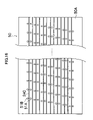
- FIG. 16 is a plan diagram showing the nozzle surface of a print head according to a fifth embodiment of the present invention.
- FIG. 17 is an enlarged diagram of the nozzle surface of the print head shown in FIG. 16 ;
- FIG. 18 is a cross-sectional diagram of the nozzle section of the print head shown in FIG. 16 .
- FIG. 1 is a diagram of the general composition of an inkjet recording apparatus according to a first embodiment of the present invention.
- the inkjet recording apparatus 10 comprises: a print unit 12 having a plurality of inkjet heads (hereafter, called “heads”) 12 K, 12 C, 12 M and 12 Y provided for ink colors of black (K), cyan (C), magenta (M), and yellow (Y), respectively; an ink storing and loading unit 14 for storing colored inks (corresponding to the first liquid, hereafter called “liquid A” for the sake of convenience) to be supplied to the print heads 12 K, 12 C, 12 M, and 12 Y, a treatment liquid storing and loading unit 15 for storing treatment liquid (corresponding to the second liquid, hereafter called “liquid B” for the sake of convenience) to be supplied to the print heads 12 K, 12 C, 12 M, and 12 Y; a paper supply unit 18 for supplying recording paper 16 ; a decurling unit 20 removing curl in the recording paper 16 ;
- heads ink
- the ink storing and loading unit 14 has ink tanks for storing the inks (liquid A) of K, C, M and Y to be supplied to the heads 12 K, 12 C, 12 M, and 12 Y, and the tanks are connected to the heads 12 K, 12 C, 12 M, and 12 Y by means of prescribed channels.
- the ink storing and loading unit 14 has a warning device (for example, a display device or an alarm sound generator) for warning when the remaining amount of any ink is low, and has a mechanism for preventing loading errors among the colors.
- the treatment liquid storing and loading unit 15 has a treatment liquid tank for storing treatment liquid (liquid B) to be supplied commonly to the heads 12 K, 12 C, 12 M, and 12 Y, and this tank is connected to the heads 12 K, 12 C, 12 M, and 12 Y by means of prescribed channels. Furthermore, the treatment liquid storing and loading unit 15 has a reporting device (display device, alarm sound generating device) for issuing a report when the remaining amount of treatment liquid has become low.
- a reporting device display device, alarm sound generating device
- one type of treatment liquid is supplied to the respective heads 12 K, 12 C, 12 M and 12 Y, but it is also possible to adopt a composition in which a plurality of different types of treatment liquids are used, with respect to the inks of different colors.
- the treatment liquid storing and loading unit 15 is provided with a mechanism for preventing the loading of the wrong type of treatment liquid.
- the heads 12 K, 12 C, 12 M and 12 Y comprise nozzles for ejecting liquid A (which correspond to the first nozzles and which may be referred to as “liquid A ejection nozzles” below, for the sake of convenience), and nozzles for ejecting liquid B (which correspond to the second nozzles and which may be referred to as “liquid B ejection nozzles” below, for the sake of convenience), these nozzles being arranged in a two-dimensional array, in such a manner that liquid A and liquid B can be deposited onto substantially the same position on the recording paper 16 .
- the ink (liquid A) used in the present embodiment is, for instance, colored ink including anionic polymer, namely, a polymer containing negatively charged surface-active ions.
- the treatment liquid (liquid B) used in the present embodiment is, for instance, transparent reaction promoting agent including cationic polymer, namely, a polymer containing positively charged surface-active ions.
- the insolubilizing reaction and/or fixing reaction of the ink coloring material proceeds due to a chemical reaction.
- the term “insolubilizing” includes a phenomenon whereby the coloring material separates or precipitates from the solvent, or a phenomenon whereby the liquid in which the coloring material is dissolved changes (coagulates) to a solid phase.
- the term “fixing” may indicate a mode where the coloring material is held on the surface of the recording medium, a mode where the coloring material permeates into the recording medium and is held therein, or a mode combining these states.
- the reaction speed can be adjusted by regulating the composition of the liquid A and the liquid B, the concentration of the materials contributing to the reaction, or the like, and desired ink insolubilizing and/or ink fixing properties (fixing speed) can be achieved.
- a magazine for rolled paper (continuous paper) is shown as an example of the paper supply unit 18 ; however, more magazines with paper differences such as paper width and quality may be jointly provided. Moreover, papers may be supplied with cassettes that contain cut papers loaded in layers and that are used jointly or in lieu of the magazine for rolled paper.
- an information recording medium such as a bar code and a wireless tag containing information about the type of paper is attached to the magazine, and by reading the information contained in the information recording medium with a predetermined reading device, the type of recording medium to be used (type of medium) is automatically determined, and ink-droplet ejection is controlled so that the ink-droplets are ejected in an appropriate manner in accordance with the type of medium.
- the recording paper 16 delivered from the paper supply unit 18 retains curl due to having been loaded in the magazine.
- heat is applied to the recording paper 16 in the decurling unit 20 by a heating drum 30 in the direction opposite from the curl direction in the magazine.
- the heating temperature at this time is preferably controlled so that the recording paper 16 has a curl in which the surface on which the print is to be made is slightly round outward.
- a cutter (first cutter) 28 is provided as shown in FIG. 1 , and the continuous paper is cut into a desired size by the cutter 28 .
- the cutter 28 has a stationary blade 28 A, of which length is not less than the width of the conveyor pathway of the recording paper 16 , and a round blade 28 B, which moves along the stationary blade 28 A.
- the stationary blade 28 A is disposed on the reverse side of the printed surface of the recording paper 16
- the round blade 28 B is disposed on the printed surface side across the conveyor pathway.
- the decurled and cut recording paper 16 is delivered to the suction belt conveyance unit 22 .
- the suction belt conveyance unit 22 has a configuration in which an endless belt 33 is set around rollers 31 and 32 so that the portion of the endless belt 33 facing at least the nozzle face of the printing unit 12 and the sensor face of the print determination unit 24 forms a horizontal plane (flat plane).
- the belt 33 has a width that is greater than the width of the recording paper 16 , and a plurality of suction apertures (not shown) are formed on the belt surface.
- a suction chamber 34 is disposed in a position facing the sensor surface of the print determination unit 24 and the nozzle surface of the printing unit 12 on the interior side of the belt 33 , which is set around the rollers 31 and 32 , as shown in FIG. 1 .
- the suction chamber 34 provides suction with a fan 35 to generate a negative pressure, and the recording paper 16 is held on the belt 33 by suction.
- the belt 33 is driven in the clockwise direction in FIG. 1 by the motive force of a motor 88 (shown in FIG. 9 ) being transmitted to at least one of the rollers 31 and 32 , which the belt 33 is set around, and the recording paper 16 held on the belt 33 is conveyed from left to right in FIG. 1 .
- a motor 88 shown in FIG. 9
- a belt-cleaning unit 36 is disposed in a predetermined position (a suitable position outside the printing area) on the exterior side of the belt 33 .
- the details of the configuration of the belt-cleaning unit 36 are not shown, examples thereof include a configuration in which the belt 33 is nipped with cleaning rollers such as a brush roller and a water absorbent roller, an air blow configuration in which clean air is blown onto the belt 33 , or a combination of these.
- the inkjet recording apparatus 10 can comprise a roller nip conveyance mechanism, in which the recording paper 16 is pinched and conveyed with nip rollers, instead of the suction belt conveyance unit 22 .
- a roller nip conveyance mechanism in which the recording paper 16 is pinched and conveyed with nip rollers, instead of the suction belt conveyance unit 22 .
- the suction belt conveyance in which nothing comes into contact with the image surface in the printing area, as shown in the present embodiment, is preferable.
- a heating fan 40 is disposed on the upstream side of the printing unit 12 in the conveyance pathway formed by the suction belt conveyance unit 22 .
- the heating fan 40 blows heated air onto the recording paper 16 to heat the recording paper 16 immediately before printing so that the ink deposited on the recording paper 16 dries more easily.
- the print heads 12 K, 12 M, 12 C and 12 Y of the print unit 12 are full line heads having a length corresponding to the maximum width of the recording paper 16 used with the inkjet recording apparatus 10 (see FIG. 2 ), and comprising a plurality of nozzles for ejecting ink and nozzles for ejecting treatment liquid arranged on a nozzle face through a length exceeding at least one edge of the maximum-size recording paper (namely, the full width of the printable range).
- the print heads 12 K, 12 C, 12 M and 12 Y are arranged in color order (black (K), cyan (C), magenta (M), yellow (Y)) from the upstream side in the feed direction of the recording paper 16 , and these respective heads 12 K, 12 C, 12 M and 12 Y are fixed extending in a direction substantially perpendicular to the conveyance direction of the recording paper 16 .
- a color image can be formed on the recording paper 16 by ejecting inks of different colors from the heads 12 K, 12 C, 12 M and 12 Y, respectively, onto the recording paper 16 while the recording paper 16 is conveyed by the suction belt conveyance unit 22 .
- ink colors and the number of colors are not limited to those.
- Light inks, dark inks or special color inks can be added as required.
- inkjet heads for ejecting light-colored inks such as light cyan and light magenta are added.
- sequence in which the heads of respective colors are arranged there are no particular restrictions of the sequence in which the heads of respective colors are arranged.
- the print determination unit 24 shown in FIG. 1 has an image sensor for capturing an image of the ink-droplet deposition result of the printing unit 12 , and functions as a device to check for ejection defects such as clogs of the nozzles in the printing unit 12 from the ink-droplet deposition results evaluated through the image sensor.
- the print determination unit 24 of the present embodiment is configured with at least a line sensor having rows of photoelectric transducing elements with a width that is greater than the ink-droplet ejection width (image recording width) of the heads 12 K, 12 C, 12 M, and 12 Y
- This line sensor has a color separation line CCD sensor including a red (R) sensor row composed of photoelectric transducing elements (pixels) arranged in a line provided with an R filter, a green (G) sensor row with a G filter, and a blue (B) sensor row with a B filter.
- R red
- G green
- B blue
- a test pattern or the target image printed by the print heads 12 K, 12 C, 12 M, and 12 Y of the respective colors is read in by the print determination unit 24 , and the ejection performed by each head is determined.
- the ejection determination includes detection of the ejection, measurement of the dot size, and measurement of the dot formation position.
- a post-drying unit 42 is disposed following the print determination unit 24 .
- the post-drying unit 42 is a device to dry the printed image surface, and includes a heating fan, for example. It is preferable to avoid contact with the printed surface until the printed ink dries, and a device that blows heated air onto the printed surface is preferable.
- a heating/pressurizing unit 44 is disposed following the post-drying unit 42 .
- the heating/pressurizing unit 44 is a device to control the glossiness of the image surface, and the image surface is pressed with a pressure roller 45 having a predetermined uneven surface shape while the image surface is heated, and the uneven shape is transferred to the image surface.
- the printed matter generated in this manner is outputted from the paper output unit 26 .
- the target print i.e., the result of printing the target image
- the test print are preferably outputted separately.
- a sorting device (not shown) is provided for switching the outputting pathways in order to sort the printed matter with the target print and the printed matter with the test print, and to send them to paper output units 26 A and 26 B, respectively.
- the test print portion is cut and separated by a cutter (second cutter) 48 .
- the cutter 48 is disposed directly in front of the paper output unit 26 , and is used for cutting the test print portion from the target print portion when a test print has been performed in the blank portion of the target print.
- the structure of the cutter 48 is the same as the first cutter 28 described above, and has a stationary blade 48 A and a round blade 48 B.
- the paper output unit 26 A for the target prints is provided with a sorter for collecting prints according to print orders.
- the heads 12 K, 12 C, 12 M and 12 Y of the respective ink colors have the same structure, and a reference numeral 50 is hereinafter designated to any of the heads.
- FIG. 3 is a plan diagram showing a schematic view of an example of a nozzle arrangement in the print head 50 .
- reference numeral 51 A indicates a nozzle forming an ejection port for ejecting ink (liquid A) (corresponding to a first nozzle and referred to as a “liquid A ejection nozzle” below, as and when necessary)
- reference numeral 51 B indicates a nozzle forming an ejection port for ejecting treatment liquid (liquid B) (corresponding to a second nozzle and referred to as a “liquid B ejection nozzle” below, as and when necessary).
- the liquid A ejection nozzles 51 A and the liquid B ejection nozzles 51 B are arranged respectively in a two-dimensional matrix array at standard arrangement intervals in a row direction which follows a direction (indicated by arrow M; main scanning direction) that is perpendicular to the conveyance direction of the recording medium (indicated by arrow S; sub-scanning direction), and an oblique column direction having a uniform non-perpendicular angle ⁇ with respect to this row direction.
- the liquid B ejection nozzles 51 B are arranged adjacently to the respective liquid A ejection nozzles 51 A in such a manner that they are arranged on the same line in the sub-scanning direction.
- L AB the nozzle-to-nozzle distance between the liquid A ejection nozzle 51 A and the liquid B ejection nozzle 51 B adjacent to each other in the sub-scanning direction
- L AA the distance in the sub-scanning direction between the mutually adjacent liquid A ejection nozzles 51 A arranged in separate rows that are mutually adjacent in the sub-scanning direction (the distance between the rows of the liquid A ejection nozzles 51 A) to be L AA
- the arrangement can be treated equivalently to a nozzle arrangement in which the respective
- FIG. 3 shows a schematic illustration, and by adopting a matrix type nozzle arrangement of this kind, it is possible to achieve a high-density nozzle composition in which the liquid A ejection nozzles reach a density of 1800 to 2400 nozzles per inch when projected to an alignment in the main scanning direction.
- the two-dimensional arrangement of the liquid B ejection nozzles 51 B is offset by a distance of L AB in the sub-scanning direction with respect to the two-dimensional arrangement of the liquid A ejection nozzles 51 A, and therefore a similar pitch to that of the liquid A ejection nozzles 51 A is also achieved for the liquid B ejection nozzles 51 B (in the case of the present embodiment, the arrangement density of the liquid B ejection nozzles is the same as the arrangement density of the liquid A ejection nozzles).
- FIG. 4 is a plan view perspective diagram of the principal part of the internal composition of the print head 50
- FIG. 5 is a cross-sectional diagram, along line 5 - 5 in FIG. 4 , showing the flow channel structure of an ejection element corresponding to a pair comprising a liquid A ejection nozzle 51 A and a liquid B ejection nozzle 51 B. As shown in FIGS.
- a pressure chamber 52 A connected to a liquid A ejection nozzle 51 A (corresponding to a first pressure chamber, which may be referred to as “liquid A pressure chamber” below, as and when necessary) and a pressure chamber 52 B connected to a liquid B ejection nozzle 51 B (corresponding to a second pressure chamber, which may be referred to as “liquid B pressure chamber” below, as and when necessary) are arranged in a layered structure in the thickness direction of the head, which is perpendicular to the nozzle surface 50 A.
- an ejection element unit constituted by one liquid A ejection nozzle 51 A and a corresponding liquid A pressure chamber 52 A, and the like, is called an ink chamber unit 53 A
- an ejection element unit constituted by one liquid B ejection nozzle 51 B and a corresponding liquid B pressure chamber 52 B, and the like, is called a treatment liquid chamber unit 53 B.
- Each of the pressure chambers 52 A and 52 B has an approximately square planar shape (the shape of the chamber when viewed in a direction perpendicular to the nozzle surface 50 A, in other words, the planar shape of the pressure chamber when projected to a plane parallel to the nozzle surface 50 A) (see FIG. 4 ).
- the liquid B pressure chamber 52 B is disposed in a position that is offset from the liquid A pressure chamber 52 A in the sub-scanning direction, and hence the pressure chambers 52 A and 52 B are arranged in a layered fashion in the print head 50 in such a manner that they are partially overlapping. More specifically, as shown in FIG.
- the pressure chambers 52 A and 52 B having this overlapping relationship are arranged in such a manner that the non-overlapping portions of the pressure chambers 52 A and 52 B are aligned in the sub-scanning direction.
- a high density of the effective nozzle pitch is achieved.
- the pressure chamber 52 A and the pressure chamber 52 B are overlapping in a layered structure, and by arranging the non-overlapping sections of the pressure chambers so as to be aligned in the sub-scanning direction, the nozzles can be arranged at high density.
- each of the pressure chambers 52 A and 52 B has an outlet port (nozzle flow channel connection port) connecting to a nozzle ( 51 A or 51 B), and a supply port 54 A or 54 B connected to the supply side, provided at respective ends of one diagonal line of the approximately square planar shape of the chamber.
- the liquid A pressure chamber 52 A is connected through the supply port 54 A to a supply side common flow channel 55 A (which corresponds to a first common flow channel and may be called “liquid A common flow channel” below, as and when necessary), and the liquid B pressure chamber 52 B is connected through the supply port 54 B to a supply side common flow channel 55 B (which corresponds to a second common flow channel and may be called “liquid B common flow channel” below, as and when necessary).
- the print head 50 is manufactured by layering and bonding together a plurality of plate members ( 111 to 123 ), and has an internal structure in which the liquid A pressure chambers 52 A and the liquid B pressure chambers 52 B are formed in a layered fashion in the direction of lamination (the vertical direction in FIG. 5 ).
- the liquid A ejection nozzle 51 A connecting to the liquid A pressure chamber 52 and the liquid B pressure chamber nozzle 51 B connecting to the liquid B pressure chamber 52 B are formed in the nozzle plate 111 , which forms the bottommost surface of the head.
- a “nozzle” is the final aperture portion from which liquid is ejected.
- the nozzle size is designed to a diameter of approximately several tens ⁇ m, and to a length of several tens ⁇ m.
- the nozzles 51 A and 51 B are formed to have shapes whereby the axes of the ejection ports are inclined respectively to a prescribed nozzle inclination angle, in order to restrict the direction of flight of the liquid droplets in such a manner that the two types of liquid ejected in a substantially simultaneous fashion from the nozzles land on substantially the same position on the recording medium.
- liquid A common flow channel 55 A for supplying ink (liquid A) to the lower-positioned liquid A pressure chamber 52 A and the liquid B common flow channel 55 B for supplying a treatment liquid (liquid B) to the upper-positioned liquid B pressure chamber 52 B are provided in the head 50 , and the respective common flow channels 55 A and 55 B are arranged in respectively different layers corresponding to the pressure chambers 52 A and 52 B, as illustrated in FIG. 5 .
- the liquid A pressure chamber 52 A is connected to the liquid A common flow channel 55 A via the supply port 54 A, and it is also connected to the liquid A ejection nozzle 51 A forming an ink ejection port via the first nozzle flow channel 57 A.
- the liquid B pressure chamber 52 B is connected to the liquid B common flow channel 55 B via the supply port 54 B, and it is also connected to the liquid B ejection nozzle 51 B forming the treatment liquid ejection port via the second nozzle flow channel 57 B.
- the liquid A common flow channel 55 A is connected to an ink tank (not shown in FIG. 5 , but indicated by reference numeral 60 A in FIG. 8 ), which is a base tank that supplies ink, and the ink supplied from the ink tank 60 is delivered through the liquid A common flow channel 55 A in FIG. 5 to the respective liquid A pressure chambers 52 A.
- the liquid B common flow channel 55 B is connected to a treatment liquid tank forming a supply source for a treatment liquid (liquid B) (this tank is not illustrated in FIG. 5 and is denoted with reference numeral 60 B in FIG. 8 ), and the treatment liquid supplied from the treatment liquid tank 60 B is distributed to the respective liquid B pressure chambers 52 B via the liquid B common flow channel 55 B in FIG. 5 .
- reference numeral 58 A denotes a first actuator which applies an ejection energy to the ink by pressurizing the liquid A pressure chamber 52 A
- reference numeral 58 B denotes a second actuator which applies an ejection energy to the treatment liquid by pressurizing the liquid B pressure chamber 52 B.
- a piezoelectric body such as a piezo element, is suitable as the actuators 58 A and 58 B.
- the liquid A ejection nozzles 51 A and the liquid B ejection nozzles 51 B are formed in the same nozzle plate 111 , and the distance from the liquid A pressure chamber 52 A to the liquid A ejection nozzle 51 A (the length of the first nozzle flow channel 57 A) is different to the distance from the liquid B pressure chamber 52 B to the liquid B ejection nozzle 51 B (the length of the second nozzle flow channel 57 B).
- a liquid A having a relatively higher viscosity of the two types of liquid is supplied to the pressure chamber that is nearer to the nozzle plate 111 (liquid A pressure chamber 52 A), and the liquid A is ejected from the liquid A ejection nozzle 51 A, whereas the liquid B having a relatively lower viscosity is supplied to the pressure chamber that is further from the nozzle plate 111 (liquid B pressure chamber 52 B), and the liquid B is ejected from the liquid B ejection nozzle 51 B.
- the respective shapes (cross-sectional area and length) of the first nozzle flow channel 57 A and the second nozzle flow channel 57 B are designed in such a manner that, when the first actuator 58 A and the second actuator 58 B are driven under prescribed common conditions, the ratio in the ejection volumes of the liquid A and the liquid B is a prescribed value.
- the first nozzle flow channel 57 A is a uniform circular tube of radius r and length h.
- the second nozzle flow channel 57 B has a structure composed of two circular tubes of different radii. More specifically, the second nozzle supply channel 57 B is composed of, from the side nearest to the liquid B pressure chamber 52 B, a circular tube of radius r 1 and length h 1 (hereinafter, called the “thick tube”), and a circular tube of radius r 2 ( ⁇ r 1 ) and length h 2 (hereinafter, called the “thin tube”), these tubes being connected in such a manner that the central axes thereof are mutually coinciding.
- a flow channel is formed by combining circular tubes of different radii in this manner, then by situating the tubes in such a manner that the radius becomes smaller, sequentially, from the side adjacent to the pressure chamber, the number of stagnant points within the nozzle flow channel is reduced, and hence bubble elimination properties and refilling properties are improved.
- a print head 50 having this structure can be fabricated by bonding the plurality of plate members ( 111 to 123 ) including a flow channel plate comprising a thin plate made of stainless steel, or the like, formed with holes and/or grooves, by means of etching, or the like.
- a flow channel plate comprising a thin plate made of stainless steel, or the like, formed with holes and/or grooves, by means of etching, or the like.
- circular tubes of different radii are constituted by different flow channel plates.
- layers are formed from the bottom in the following sequence: the nozzle plate 111 , a first nozzle flow channel plate 112 , a second nozzle flow channel plate 113 , a first common flow channel plate 114 , a first supply port plate 115 , a first pressure chamber plate 116 , a first diaphragm plate 117 , an actuator avoiding plate 118 , a third nozzle supply channel plate 119 , a second common flow channel plate 120 , a second supply port plate 121 , a second pressure chamber plate 122 , and a second diaphragm plate 123 .
- the first nozzle flow channel plate 112 is a member which constitutes a portion of the first nozzle flow channel 57 A and the thin tube of the second nozzle flow channel 57 B.
- the second nozzle flow channel plate 113 is a member which constitutes a portion of the first nozzle flow channel 57 A and the thick tube of the second nozzle flow channel 57 B.
- the first common flow channel plate 114 is a member which constitutes the side walls of the liquid A common flow channel 55 A, a portion of the first nozzle flow channel 57 A, and a portion of the thick tube of the second nozzle flow channel 57 B.
- the first supply port plate 115 is a member which constitutes the supply port 54 A (corresponding to the first supply ports), a portion of the first nozzle flow channel 57 A, and a portion of the thick tube of the second nozzle flow channel 57 B.
- the first pressure chamber plate 116 is a member which constitutes the side walls of the liquid A pressure chamber 52 A and a portion of the thick tube of the second nozzle flow channel 57 B.
- the first vibration plate 117 is a member which seals the upper face of the liquid A pressure chamber 52 A (forming the ceiling thereof), and furthermore, also constitutes a portion of the thick tube of the second nozzle supply channel 57 B.
- a first actuator 58 A is fixed to the first diaphragm plate 117 , in a position corresponding to each liquid A pressure chamber 52 A.
- the actuator avoiding plate 118 has a recess section 118 A for ensuring a space in which the first actuator 58 A is disposed, and it allows lamination of further layers above the first actuator 58 A. Moreover, the actuator avoiding plate 118 constitutes a portion of the thick tube of the second nozzle flow channel 57 B.
- the third nozzle flow channel plate 119 is a member constituting a portion of the thick tube of the second nozzle flow channel 57 B.
- the second common flow channel plate 120 is a member which constitutes the side walls of the liquid B common flow channel 55 B and a portion of the thick tube of the second nozzle flow channel 57 B.
- the second supply port channel plate 121 is a member which constitutes the second supply port 54 B and a portion of the thick tube of the second nozzle flow channel 57 B.
- the second pressure chamber plate 122 is a member which constitutes the side walls of the liquid B pressure chamber 52 B.
- the second diaphragm plate 123 is a member sealing the upper surface of the liquid B pressure chamber 52 B (forming the ceiling face thereof), and a second actuator 58 B is fixed to the upper surface of the second diaphragm plate 123 in a position corresponding to the liquid B pressure chamber 52 B.
- each of the actuators 58 A and 58 B electrodes (not illustrated) are formed, and the electrodes are connected to a driving circuit (not illustrated), by means of wiring (not illustrated). It is possible to use the first diaphragm plate 117 and the second diaphragm plate 123 as the electrodes.
- the first actuator 58 A When a drive voltage is applied between the electrodes of the first actuator 58 A, the first actuator 58 A deforms, the volume of the liquid A pressure chamber 52 A changes, and due to the consequent pressure change, a droplet of ink is ejected from the liquid A ejection nozzle 51 A. After ejecting ink, new ink is supplied (replenished) to the liquid A pressure chamber 52 A from the liquid A common flow channel 55 A, via the supply port 54 A.
- the high-density nozzle head according to the present embodiment is achieved by arranging a plurality of ink chamber units 53 A and treatment liquid chamber units 53 B having the structure illustrated in FIGS. 4 and 5 in a lattice arrangement, based on a fixed arrangement pattern having a row direction which coincides with the lengthwise direction of the head (main scanning direction), and a column direction which is inclined at a fixed angle of ⁇ with respect to the main scanning direction, rather than being perpendicular to the main scanning direction.
- the “main scanning” is defined as printing one line (a line formed of a row of dots, or a line formed of a plurality of rows of dots) in the width direction of the recording paper (the direction perpendicular to the conveyance direction of the recording paper) by driving the nozzles in one of the following ways: (1) simultaneously driving all the nozzles; (2) sequentially driving the nozzles from one side toward the other; and (3) dividing the nozzles into blocks and sequentially driving the nozzles from one side toward the other in each of the blocks.
- 51 A- 37 are taken as one block, and so on), and one line is printed in the breadthways direction of the recording medium by successively driving the nozzles 51 A- 11 , 51 A- 12 , . . . , 51 - 17 in accordance with the conveyance speed of the recording medium.
- “sub-scanning” is defined as to repeatedly perform printing of one line (a line formed of a row of dots, or a line formed of a plurality of rows of dots) formed by the main scanning, while moving the full-line head and the recording medium relatively to each other.
- one line of dots is formed in the breadthways direction of the recording medium by successively driving the nozzles 51 B-i 1 , 51 -Bi 2 , . . . , 51 B-i 7 , from the end of the nozzle block, in accordance with the conveyance speed of the recording medium.
- each of the common flow channels 55 A and 55 B shown in FIG. 6 is a branch flow channel, which branches off from a common flow channel main passage (not shown).
- the refilling load is not concentrated at a particular common flow channel when the nozzles are driven in main scanning as described above, and hence refilling characteristics are also good. Furthermore, it is also possible to achieve high density by means of a structure in which the common flow channels 55 A and 55 B are arranged in a layered fashion within the print head 50 .
- the structure of the head and the arrangement of the nozzles is not limited to that of the example illustrated.
- a line head having nozzle rows of a length corresponding to the entire length of the recording paper 16 can be formed as shown in FIG. 7 by arranging and combining, in a staggered matrix, short head units 50 ′ each having a plurality of nozzles 51 A and 51 B arrayed in a two-dimensional fashion.
- a structure similar to that shown in FIG. 6 can also be employed for the matrix type nozzle arrangement within each head unit 50 ′.
- a method is employed in which ink or treatment liquid is ejected by means of the deformation of an actuator 58 A or 58 B, which is typically a piezoelectric element.
- the method used for ejecting the ink or treatment liquid is not limited in particular, and instead of a piezo method, it is also possible to apply various types of methods, such as a thermal jet method where the ink or treatment liquid is heated and bubbles are caused to form therein by means of a heat generating body such as a heater, droplets of the ink or treatment liquid being ejected by means of the pressure of these bubbles.
- FIG. 8 is a conceptual diagram showing the composition of an ink supply system and a treatment liquid supply system in the inkjet recording apparatus 10 .
- the ink tank 60 is a base tank for supplying the ink (liquid A) to the print head 50 , which is disposed in the ink storing and loading unit 14 illustrated in FIG. 1 .
- the treatment liquid tank 60 B illustrated in FIG. 8 is a base tank for supplying the treatment liquid (liquid B) to the head 50 , which is disposed in the treatment liquid storing and loading section 15 illustrated in FIG. 1 .
- the ink tank 60 A and the treatment liquid tank 60 B may adopt a system for replenishing ink or treatment liquid by means of a replenishment opening (not illustrated), or a cartridge system wherein cartridges are exchanged independently for each tank, whenever the residual amount of ink or treatment liquid has become low. If the type of ink or the type of treatment liquid is changed in accordance with the type of application, then a cartridge based system is suitable. In this case, desirably, type information relating to the ink or treatment liquid is identified by means of a bar code, or the like, and the ejection of the ink or treatment liquid is controlled in accordance with the identified type.
- the ink tank 60 A and the treatment liquid tank 60 B in FIG. 6 are respectively equivalent to the ink storing and loading unit 14 and the treatment liquid storing and loading unit 15 shown in FIG. 1 and described above.
- a filter 62 A is provided between the ink tank 60 A and the print head 50 , in order to remove foreign matter and air bubbles.
- a filter 62 B is provided between the treatment liquid tank 60 B and the print head 50 in order to remove foreign matter and air bubbles.
- the mesh size in the filters 62 A and 62 B is preferably equivalent to or less than the diameter of the nozzle and commonly it is about 20 ⁇ m.
- a composition is adopted in which a subsidiary tank is provided in the vicinity of the head 50 , or in an integrated manner with the head 50 .
- the subsidiary tank has the function of improving damping effects and refilling, in order to prevent variations in the internal pressure inside the head.
- the inkjet recording apparatus 10 is also provided with a cap 64 as a device to prevent the nozzles 51 A and 51 B from drying out or to prevent an increase in the ink viscosity in the vicinity of the nozzles 51 , and a cleaning blade 66 as a device to clean the nozzle face 50 A.
- a maintenance unit including the cap 64 and the cleaning blade 66 can be relatively moved with respect to the head 50 by a movement mechanism (not shown), and is moved from a predetermined holding position to a maintenance position below the head 50 as required.
- the cap 64 is displaced up and down relatively with respect to the head 50 by an elevator mechanism (not shown).
- an elevator mechanism not shown.
- the cap 64 is raised to a predetermined elevated position so as to come into close contact with the head 50 , and the nozzle face 50 A is thereby covered with the cap 64 .
- the cleaning blade 66 is composed of rubber or another elastic member, and can slide on the ink ejection surface (surface of the nozzle plate) of the head 50 by means of a blade movement mechanism (not shown). If there are ink droplets, treatment liquid droplets or foreign matter adhering to the nozzle surface 50 A, then the nozzle surface 50 A is wiped by causing the cleaning blade 66 to slide over the nozzle surface 50 A, thereby cleaning the nozzle plate surface. This wiping action is performed by sliding the cleaning blade 66 in the row direction of the nozzle arrangement illustrated in FIG. 3 , in other words, in the lengthwise direction of the print head.
- a preliminary ejection is performed onto the cap 64 , in order to remove the degraded ink or the degraded treatment liquid.
- the cap 64 is placed against the head 50 , and the liquid (namely, the liquid containing air bubbles) inside the pressure chambers 52 A and 52 B is removed by suctioning by means of the suction pump 67 , the liquid thus removed being conveyed to a collection tank 68 .
- This suction operation is also carried out in order to remove degraded ink or degraded treatment liquid having increased viscosity (namely, hardened ink or treatment liquid), when ink or treatment liquid is loaded into the print head 50 for the first time, and when the print head 50 starts to be used again after having been out of use for a long period of time.
- the actuators 58 A and 58 B are operated toward an ink receptacle (here, as which the cap 64 is also serves) in a viscosity range that allows liquid to be ejected by the operation of the actuators 58 A and 58 B, and a “preliminary ejection” is thereby performed which causes the liquid in the vicinity of the nozzle of which viscosity has increased to be ejected.
- a preliminary ejection is also carried out in order to prevent mixing of foreign matter inside the nozzles 51 A and 51 B due to the rubbing action of the wiper.
- the preliminary ejection is also referred to as “dummy ejection”, “purge”, “liquid ejection”, and so on.
- the liquid can no longer be ejected from the nozzles 51 A and 51 B even if the actuators 58 A and 58 B is operated. Also, when the liquid viscosity inside the nozzles 51 A and 51 B has increased over a certain level, the liquid can no longer be ejected from the nozzles 51 A and 51 B even if the actuator 58 is operated.
- a suctioning device to remove the liquid inside the pressure chambers 52 A and 52 B by suction with a suction pump, or the like, is placed on the nozzle face 50 A of the head 50 , and the liquid in which bubbles have become intermixed or the liquid of which viscosity has increased is removed by suction.
- a preferred aspect is one in which a preliminary discharge is performed while the increase in the viscosity of the liquid is small.
- FIG. 9 is a principal block diagram showing the system configuration of the inkjet recording apparatus 10 .
- the inkjet recording apparatus 10 comprises a communication interface 70 , a system controller 72 , an image memory 74 , a ROM 75 , a motor driver 76 , a heater driver 78 , a print controller 80 , an image buffer memory 82 , a head driver 84 , and the like.
- the communication interface 70 is an interface unit for receiving image data sent from a host computer 86 .
- a serial interface such as USB, IEEE1394, Ethernet, wireless network, or a parallel interface such as a Centronics interface may be used as the communication interface 70 .
- a buffer memory (not shown) may be mounted in this portion in order to increase the communication speed.
- the image data sent from the host computer 86 is received by the inkjet recording apparatus 10 through the communication interface 70 , and is temporarily stored in the image memory 74 .
- the image memory 74 is a storage device for temporarily storing images inputted through the communication interface 70 , and data is written and read to and from the image memory 74 through the system controller 72 .
- the image memory 74 is not limited to a memory composed of semiconductor elements, and a hard disk drive or another magnetic medium may be used.
- the system controller 72 is constituted by a central processing unit (CPU) and peripheral circuits thereof, and the like, and it functions as a control device for controlling the whole of the inkjet recording apparatus 10 in accordance with a prescribed program, as well as a calculation device for performing various calculations. More specifically, the system controller 72 controls the various sections, such as the communication interface 70 , image memory 74 , motor driver 76 , heater driver 78 , and the like, as well as controlling communications with the host computer 86 and writing and reading to and from the image memory 74 , and it also generates control signals for controlling the motor 88 and heater 89 of the conveyance system.
- CPU central processing unit
- the program executed by the CPU of the system controller 72 and the various types of data which are required for control procedures are stored in the ROM 75 .
- the ROM 75 may be a non-writeable storage device, or it may be a rewriteable storage device, such as an EEPROM.
- the image memory 74 is used as a temporary storage region for the image data, and it is also used as a program development region and a calculation work region for the CPU.
- the motor driver (drive circuit) 76 drives the motor 88 in accordance with commands from the system controller 72 .
- the heater driver (drive circuit) 78 drives the heater 89 of the post-drying unit 42 or the like in accordance with commands from the system controller 72 .
- the print controller 80 has a signal processing function for performing various tasks, compensations, and other types of processing for generating print control signals from the image data stored in the image memory 74 in accordance with commands from the system controller 72 so as to supply the generated print data (dot data) to the head driver 84 .
- Prescribed signal processing is carried out in the print controller 80 , and the ejection amount and the ejection timing of the ink and the treatment liquid are controlled via the head driver 84 , on the basis of the print data. By this means, prescribed dot size and dot positions can be achieved.
- the print controller 80 is provided with the image buffer memory 82 ; and image data, parameters, and other data are temporarily stored in the image buffer memory 82 when image data is processed in the print controller 80 .
- the aspect shown in FIG. 9 is one in which the image buffer memory 82 accompanies the print controller 80 ; however, the image memory 74 may also serve as the image buffer memory 82 . Also possible is an aspect in which the print controller 80 and the system controller 72 are integrated to form a single processor.
- the head driver 84 drives the actuators 58 A and 58 B of the heads 50 of the respective colors 12 K, 12 C, 12 M and 12 Y on the basis of print data supplied by the print controller 80 .
- the head driver 84 can be provided with a feedback control system for maintaining constant drive conditions for the print heads.
- the image data to be printed is externally inputted through the communication interface 70 , and is stored in the image memory 74 .
- the RGB image data is stored in the image memory 74 .
- the image data stored in the image memory 74 is sent to the print controller 80 through the system controller 72 , and is converted to the dot data for each ink color by a half-toning technique, such as dithering or error diffusion, in the print controller 80 .
- a half-toning technique such as dithering or error diffusion
- an image which appears to have a continuous tonal gradation to the human eye is formed by changing the droplet ejection density and the dot size of fine dots created by ink (coloring material), and therefore, it is necessary to convert the input digital image into a dot pattern which reproduces the tonal gradations of the image (namely, the light and shade toning of the image) as faithfully as possible.
- the print controller 80 performs processing for converting the inputted RGB image data into dot data for four colors, K, C, M and Y.
- the dot data generated by the print controller 80 is stored in the image buffer memory 82 .
- the head driver 84 generates drive control signals for the head 50 on the basis of the dot data stored in the image buffer memory 82 .
- ink is ejected from the head 50 .
- an image is formed on the recording paper 16 .
- the print determination unit 24 is a block that includes the line sensor as described above with reference to FIG. 1 , reads the image printed on the recording paper 16 , determines the print conditions (presence of the ejection, variation in the dot formation, optical density, and the like) by performing desired signal processing, or the like, and provides the determination results of the print conditions to the print controller 80 .
- the print controller 80 makes various corrections with respect to the head 50 on the basis of information obtained from the print determination unit 24 . Furthermore, the system controller 72 implements control for carrying out preliminary ejection, suctioning, and other prescribed restoring processes on the head 50 , on the basis of the information obtained from the print determination unit 24 .
- the inkjet recording apparatus 10 has an ink information reading unit 91 , a treatment liquid information reading unit 92 and a media type determination unit 93 .
- the ink information reading unit 91 is a device for reading in information relating to the ink type. More specifically, it is possible to use, for example, a device which reads in ink properties information from the shape of the cartridge in the ink tank 60 A (a specific shape which allows the ink type to be identified), or from a bar code or IC chip incorporated into the cartridge. Besides this, it is also possible for an operator to input the required information by means of a user interface.
- the treatment liquid information reading unit 92 is a device for acquiring information relating to the type of treatment liquid. More specifically, it is possible to use, for example, a device which reads in treatment liquid properties information from the shape of the cartridge in the treatment liquid tank 60 B (a specific shape which allows the liquid type to be identified), or from a bar code or IC chip incorporated into the cartridge. Besides this, it is also possible for an operator to input the required information by means of a user interface.
- the media type determination unit 93 is a device for determining the type and size of the recording medium.
- This section uses, for example, a device for reading in information such as bar codes attached to the magazine 32 in the media supply unit 22 , or sensors disposed at a suitable position in the paper conveyance path (a paper width determination sensor, a sensor for determining the thickness of the paper, a sensor for determining the reflectivity of the paper, and so on).
- a paper width determination sensor a sensor for determining the thickness of the paper
- a sensor for determining the reflectivity of the paper and so on.
- a suitable combination of these elements may also be used.
- the information acquired from the various devices namely, the ink information reading unit 91 , the treatment liquid information reading unit 92 and the media type determination unit 93 is sent to the system controller 72 , where it is used to control ejection of the ink and treatment liquid (namely, to control the ejection volume and ejection timing), in such a manner that suitable droplet ejection is performed in accordance with the conditions.
- the supply of electrical power to the first actuators 58 A and the second actuators 58 B is controlled in a substantially simultaneous fashion to the pair of actuators 58 A and 58 B corresponding to the first nozzle 51 A and the second nozzle 51 B that are aligned adjacently in the sub-scanning direction.
- a drive waveform is supplied in parallel to the pair of actuators 58 A and 58 B that correspond to the first nozzle 51 A and the second nozzle 51 B that are aligned adjacently in the sub-scanning direction.
- two types of liquid droplets 95 A and 95 B are ejected substantially simultaneously from the two nozzles 51 A and 51 B, as illustrated in FIG. 10A .
- the two liquid droplets 95 A and 95 B ejected simultaneously in this manner land at substantially the same timing in substantially the same location on the recording medium 96 (which corresponds to the recording paper 16 in FIG. 1 ), and as illustrated in FIG. 10B , they combine on the recording medium 96 to form one dot 97 . If the dot size is to be changed, then the first actuator 58 A and the second actuator 58 B are controlled in conjunction with each other, and the ejection volume of both liquids is controlled, as a pair.
- composition illustrated in FIG. 11 may also be adopted, instead of the structure of the print head 50 shown in FIG. 5 .
- items which are the same as or similar to those in FIG. 5 are denoted with the same reference numerals and description thereof is omitted here.
- a composition is adopted in which the liquid droplets are propelled in a substantially perpendicular direction with respect to the recording medium, rather than inclining the ejection directions of the nozzles 51 A and 51 B.
- the arrangement configuration of the nozzles 51 A and 51 B is similar to that illustrated in FIGS. 2 and 6 .
- the time difference between the landing times of the liquid ejected from the nozzles 51 A and 51 B is L AB /U, in such a manner that the liquid droplets land in substantially the same position on the recording medium.
- a composition in which the liquid A and the liquid B are caused to land on the recording medium at a slight time difference apart is desirable in a case where an ink containing a coloring material (liquid A) and a treatment liquid (liquid B) containing a reaction promoting agent are used.
- reaction agent liquid B
- coloring material liquid A
- the coloring material always lands on the reaction promoting agent and does not land directly on the recording medium.
- the coloring material landing on the droplet of the reaction promoting agent mixes with the reaction promoting agent upon landing, and immediately starts a fixing reaction. Thereby, it is possible to prevent bleeding of the dot created by the coloring material.
- reaction promoting agent lands directly on the recording medium and permeates into the recording medium, since the reaction promoting agent does not contain any coloring material, it does not cause any problem in terms of giving rise to bleeding.
- liquid B ejection nozzles 51 B are disposed at every alternate row of liquid A ejection nozzles 51 A in the sub-scanning direction with respect to the two-dimensional arrangement of liquid A ejection nozzles 51 A (in other words, liquid B ejection nozzles 51 B are arranged only at the odd-numbered rows in the sub-scanning direction).
- FIG. 13 shows an example of this dot arrangement.
- the reference numerals 211 A and 212 A indicate dots which are respectively deposited by the liquid A ejection nozzles 51 A- 11 and 51 A- 12 in FIG. 12
- reference numeral 211 B in FIG. 13 indicates a dot deposited by the liquid B ejection nozzle 51 B- 11 in FIG. 12 .
- the liquid B ejection nozzles 51 B- 11 previously deposits the dot 211 B at a slight time difference before the dots 211 A and 212 A deposited by the nozzle 51 A- 11 and the nozzle 51 A- 12 .
- the dot size D B of the dot 211 B is set to value whereby the dot has a surface area to cover the droplet ejection region (dot coverage region) of the dot 211 A and the dot 211 B of liquid A.
- the central point B 1 of the dot 211 B is situated in the approximate center of the line A 1 -A 2 linking the centers of the dots 211 A and 212 A.
- a composition for obtaining a dot arrangement of this kind as shown in FIG. 13 , as shown in FIG.
- the liquid A ejection nozzles 51 A are composed so as to propel the liquid droplets in a substantially perpendicular direction with respect to the recording medium, rather than inclining the ejection directions, and the liquid B ejection nozzles 51 B are set to a nozzle inclination angle whereby the ejected liquid lands at a central position B 1 between the dots formed by the droplets ejected from the liquid A ejection nozzles 51 A.
- droplet ejection is controlled in such a manner that a dot 211 B is deposited only when at least one of the dots 211 A and 212 A is to be deposited.
- FIG. 15 is a plan view perspective diagram showing the principal part of an example of the structure of a print head according to a fourth embodiment of the present invention.
- items which are the same as or similar to the composition in FIG. 6 are denoted with the same reference numerals and description thereof is omitted here.
- the embodiment shown in FIG. 15 has a structure in which the liquid A pressure chambers 52 A and the liquid B pressure chambers 52 B are arranged in a planar fashion, without overlapping with each other.
- a planar structure of this kind makes the manufacturing process easier compared to the case of a layered structure as illustrated in FIG. 6 .
- a liquid A ejection nozzle 51 A-ij and a liquid B ejection nozzle 51 B-ij are aligned in mutually adjacent positions in the sub-scanning direction (the conveyance direction of the recording medium).
- This composition is similar to the embodiment shown in FIG. 6 in that a nozzle 51 A-ij or 51 B-ij and a supply port 54 A or 54 B are arranged on a diagonal of each pressure chamber 52 A, 52 B, which has an approximately square planar shape.
- common flow channels 55 A and 55 B are disposed following the nozzle rows extending in the main scanning direction (lengthwise direction of the print head). This composition simplifies the manufacturing process, since it does not require a layered structure to be adopted for the common flow channels 55 A and 55 B.
- FIG. 16 is a plan diagram showing the nozzle surface of a print head according to a fifth embodiment
- FIG. 17 is an enlarged diagram of FIG. 16
- FIG. 18 is a cross-sectional diagram of a principal part thereof.
- items which are the same as or similar to the composition in FIGS. 3 to 6 are denoted with the same reference numerals and description thereof is omitted here.
- grooves 240 parallel to the lengthwise direction of the head are formed on the nozzle surface 50 A of the print head 50 , at the boundaries between the liquid A ejection nozzles 51 A and the liquid B ejection nozzles 51 B.
- wiping is performed by sliding the cleaning blade 66 in the row direction of the nozzle arrangement (the lengthwise direction of the print head).
- the liquid adhering to the nozzle surface 50 A moves over the nozzle surface 50 A due to the wiping action, but if two different types of liquid enter into the nozzle apertures, then a combined reaction of the liquids will occur.
- the grooves 240 are provided as a device for preventing mixture of the liquids, (in other words, a device for restricting the range of movement of the liquids), between the liquid A ejection nozzles 51 A and the liquid B ejection nozzles 51 B.
- a device for restricting the range of movement of the liquids instead of the grooves 240 or in conjunction with same, it is also possible to provide projection-shaped dividing members (not illustrated), for example.
- FIGS. 16 to 18 show an example in which the grooves 240 for preventing mixture are appended to the head composition illustrated in FIGS. 3 to 6 , but similarly, it is also possible to adopt a composition in which a mechanism for preventing mixture of the two liquids via the nozzle surface 50 A (groove, or dividing members) is appended to the head compositions illustrated in FIGS. 11 to 15 .
- the reaction promoting agent has been described as an example of a treatment liquid, but a mode is also possible in which a permeation retarding agent is used instead of a reaction promoting agent.
- the permeation retarding agent has a function of delaying the progress of permeation of the ink into the recording medium, by combining with the ink (liquid A) containing coloring material. This is suitable for use in the case of a recording medium such as standard paper, in which the liquid permeates while diffusing in the planar direction within the medium, and which is therefore liable to bleeding.
- an inkjet recording apparatus has been described as one example of an image forming apparatus, but the scope of application of the present invention is not limited to this.
- the liquid droplet ejection head according to the present invention may also be applied to a photographic image forming apparatus in which developing solution is applied onto a printing paper by means of a non-contact method.
- the scope of application of the liquid droplet ejection head according to the present invention is not limited to an image forming apparatus, and the present invention may also be applied to various other types of apparatuses which spray a processing liquid, or other liquid, toward an ejection receiving medium by means of an ejection head (such as a coating device, wiring pattern printing device, or the like).
Landscapes
- Ink Jet (AREA)
- Particle Formation And Scattering Control In Inkjet Printers (AREA)
Abstract
Description
Claims (14)
Applications Claiming Priority (2)
| Application Number | Priority Date | Filing Date | Title |
|---|---|---|---|
| JP2004-210593 | 2004-07-16 | ||
| JP2004210593A JP2006027132A (en) | 2004-07-16 | 2004-07-16 | Liquid droplet discharge head and image forming apparatus |
Publications (2)
| Publication Number | Publication Date |
|---|---|
| US20060012622A1 US20060012622A1 (en) | 2006-01-19 |
| US7448710B2 true US7448710B2 (en) | 2008-11-11 |
Family
ID=35598971
Family Applications (1)
| Application Number | Title | Priority Date | Filing Date |
|---|---|---|---|
| US11/180,704 Expired - Fee Related US7448710B2 (en) | 2004-07-16 | 2005-07-14 | Liquid droplet ejection head and image forming apparatus |
Country Status (2)
| Country | Link |
|---|---|
| US (1) | US7448710B2 (en) |
| JP (1) | JP2006027132A (en) |
Cited By (3)
| Publication number | Priority date | Publication date | Assignee | Title |
|---|---|---|---|---|
| US20160034231A1 (en) * | 2014-07-30 | 2016-02-04 | Canon Kabushiki Kaisha | Printing apparatus and print control method |
| US11642886B2 (en) | 2021-04-08 | 2023-05-09 | Funai Electric Co., Ltd. | Modified fluid jet plume characteristics |
| US11642887B2 (en) | 2021-04-22 | 2023-05-09 | Funai Electric Co., Ltd. | Ejection head having optimized fluid ejection characteristics |
Families Citing this family (7)
| Publication number | Priority date | Publication date | Assignee | Title |
|---|---|---|---|---|
| US8349409B2 (en) * | 2006-01-31 | 2013-01-08 | Brother Kogyo Kabushiki Kaisha | Pattern forming method, method for forming composite-metal oxide film and method for coating two-liquid reaction curing type adhesive |
| JP5043539B2 (en) * | 2007-07-02 | 2012-10-10 | キヤノン株式会社 | Manufacturing method of liquid jet recording head |
| JP5228688B2 (en) | 2008-08-08 | 2013-07-03 | ブラザー工業株式会社 | Droplet discharge head and inkjet head |
| US11453226B2 (en) * | 2017-09-29 | 2022-09-27 | Kyocera Corporation | Liquid ejecting head and recording device |
| JP7063178B2 (en) * | 2018-08-06 | 2022-05-09 | ブラザー工業株式会社 | Discharge plate and head |
| JP7110873B2 (en) * | 2018-09-27 | 2022-08-02 | セイコーエプソン株式会社 | Inkjet recording method and inkjet recording apparatus |
| KR20220134813A (en) * | 2021-03-25 | 2022-10-06 | 삼성디스플레이 주식회사 | Apparatus for manufacturing display device, manufacturing method using the same and display device manufactured by the same |
Citations (17)
| Publication number | Priority date | Publication date | Assignee | Title |
|---|---|---|---|---|
| JPH028059A (en) | 1988-06-28 | 1990-01-11 | Canon Inc | liquid jet recording head |
| JPH04329151A (en) | 1991-04-30 | 1992-11-17 | Fujitsu Ltd | Recording apparatus |
| JPH05338173A (en) | 1992-06-08 | 1993-12-21 | Canon Inc | Ink jet recording apparatus |
| JPH0852867A (en) | 1994-08-10 | 1996-02-27 | Canon Inc | Ink jet recording device |
| JPH09136417A (en) | 1995-09-14 | 1997-05-27 | Canon Inc | Liquid ejection head and liquid ejection device |
| JPH1024564A (en) | 1996-07-11 | 1998-01-27 | Canon Inc | Liquid discharge recording method and liquid discharge head |
| JPH10157111A (en) | 1996-11-26 | 1998-06-16 | Canon Inc | Ink jet head unit, ink jet cartridge, and ink jet device |
| US6070972A (en) * | 1993-10-19 | 2000-06-06 | Francotyp-Postalia Ag & Co. | Face shooter ink jet printing head |
| US6179412B1 (en) | 1995-09-14 | 2001-01-30 | Canon Kabushiki Kaisha | Liquid discharging head, having opposed element boards and grooved member therebetween |
| JP2001146010A (en) | 1999-11-18 | 2001-05-29 | Nec Corp | Ink-jet recording head |
| JP2001334661A (en) | 2000-03-21 | 2001-12-04 | Nec Corp | Ink jet head |
| JP2002036519A (en) | 2000-07-25 | 2002-02-05 | Sharp Corp | Ink jet image forming apparatus and ink jet image forming method |
| US20020018095A1 (en) | 2000-03-21 | 2002-02-14 | Hirofumi Nakamura | Ink jet head |
| US20020024557A1 (en) * | 2000-08-28 | 2002-02-28 | Nobuo Matsumoto | Line head and image recording method |
| US6375819B1 (en) * | 1997-06-30 | 2002-04-23 | Spectrumedix Corporation | Fluid delivery system for capillary electrophoretic applications |
| JP2002240328A (en) | 2001-02-15 | 2002-08-28 | Sharp Corp | Inkjet printer |
| US6921151B2 (en) * | 2001-01-30 | 2005-07-26 | Matsushita Electric Industrial Co., Ltd. | Ink jet head, actuator testing method, method of manufacturing ink jet head, and ink jet recording apparatus |
-
2004
- 2004-07-16 JP JP2004210593A patent/JP2006027132A/en active Pending
-
2005
- 2005-07-14 US US11/180,704 patent/US7448710B2/en not_active Expired - Fee Related
Patent Citations (18)
| Publication number | Priority date | Publication date | Assignee | Title |
|---|---|---|---|---|
| JPH028059A (en) | 1988-06-28 | 1990-01-11 | Canon Inc | liquid jet recording head |
| JPH04329151A (en) | 1991-04-30 | 1992-11-17 | Fujitsu Ltd | Recording apparatus |
| JPH05338173A (en) | 1992-06-08 | 1993-12-21 | Canon Inc | Ink jet recording apparatus |
| US6070972A (en) * | 1993-10-19 | 2000-06-06 | Francotyp-Postalia Ag & Co. | Face shooter ink jet printing head |
| JPH0852867A (en) | 1994-08-10 | 1996-02-27 | Canon Inc | Ink jet recording device |
| US6179412B1 (en) | 1995-09-14 | 2001-01-30 | Canon Kabushiki Kaisha | Liquid discharging head, having opposed element boards and grooved member therebetween |
| JPH09136417A (en) | 1995-09-14 | 1997-05-27 | Canon Inc | Liquid ejection head and liquid ejection device |
| JPH1024564A (en) | 1996-07-11 | 1998-01-27 | Canon Inc | Liquid discharge recording method and liquid discharge head |
| JPH10157111A (en) | 1996-11-26 | 1998-06-16 | Canon Inc | Ink jet head unit, ink jet cartridge, and ink jet device |
| US6375819B1 (en) * | 1997-06-30 | 2002-04-23 | Spectrumedix Corporation | Fluid delivery system for capillary electrophoretic applications |
| JP2001146010A (en) | 1999-11-18 | 2001-05-29 | Nec Corp | Ink-jet recording head |
| US6371603B1 (en) | 1999-11-18 | 2002-04-16 | Nec Corporation | Ink-jet recording head with stacked individual head units |
| JP2001334661A (en) | 2000-03-21 | 2001-12-04 | Nec Corp | Ink jet head |
| US20020018095A1 (en) | 2000-03-21 | 2002-02-14 | Hirofumi Nakamura | Ink jet head |
| JP2002036519A (en) | 2000-07-25 | 2002-02-05 | Sharp Corp | Ink jet image forming apparatus and ink jet image forming method |
| US20020024557A1 (en) * | 2000-08-28 | 2002-02-28 | Nobuo Matsumoto | Line head and image recording method |
| US6921151B2 (en) * | 2001-01-30 | 2005-07-26 | Matsushita Electric Industrial Co., Ltd. | Ink jet head, actuator testing method, method of manufacturing ink jet head, and ink jet recording apparatus |
| JP2002240328A (en) | 2001-02-15 | 2002-08-28 | Sharp Corp | Inkjet printer |
Cited By (6)
| Publication number | Priority date | Publication date | Assignee | Title |
|---|---|---|---|---|
| US20160034231A1 (en) * | 2014-07-30 | 2016-02-04 | Canon Kabushiki Kaisha | Printing apparatus and print control method |
| CN105313505A (en) * | 2014-07-30 | 2016-02-10 | 佳能株式会社 | Printing apparatus and print control method |
| US9411544B2 (en) * | 2014-07-30 | 2016-08-09 | Canon Kabushiki Kaisha | Printing apparatus and print control method controlling printing based on acquired information relating to conveyance of a print medium |
| CN105313505B (en) * | 2014-07-30 | 2018-04-03 | 佳能株式会社 | Printing device and print control program |
| US11642886B2 (en) | 2021-04-08 | 2023-05-09 | Funai Electric Co., Ltd. | Modified fluid jet plume characteristics |
| US11642887B2 (en) | 2021-04-22 | 2023-05-09 | Funai Electric Co., Ltd. | Ejection head having optimized fluid ejection characteristics |
Also Published As
| Publication number | Publication date |
|---|---|
| JP2006027132A (en) | 2006-02-02 |
| US20060012622A1 (en) | 2006-01-19 |
Similar Documents
| Publication | Publication Date | Title |
|---|---|---|
| US7854487B2 (en) | Image forming method and apparatus | |
| US7448706B2 (en) | Image forming apparatus and method | |
| US7614734B2 (en) | Inkjet recording apparatus and method | |
| US7357472B2 (en) | Inkjet recording apparatus and method | |
| US20070064026A1 (en) | Image forming method and image forming apparatus | |
| US7275801B2 (en) | Image forming apparatus | |
| US7530684B2 (en) | Inkjet recording apparatus | |
| US7628474B2 (en) | Liquid discharging head with recess in vibration plate | |
| US7422300B2 (en) | Image forming apparatus and image forming method | |
| US7527369B2 (en) | Image forming apparatus and method for improving the fixing characteristics of ink | |
| US7448710B2 (en) | Liquid droplet ejection head and image forming apparatus | |
| US20060214970A1 (en) | Image forming apparatus and method | |
| US7328982B2 (en) | Liquid droplet discharge head, liquid droplet discharge device, and image forming apparatus | |
| US7591519B2 (en) | Liquid droplet ejection apparatus and image forming apparatus | |
| US7316468B2 (en) | Liquid droplet ejection head, liquid droplet ejection device and image forming apparatus | |
| US7503643B2 (en) | Liquid droplet discharge head and image forming apparatus | |
| US7273267B2 (en) | Bubble-eliminating liquid filling method, droplet discharging apparatus, and inkjet recording apparatus | |
| US7681998B2 (en) | Laminated piezoelectric element, liquid droplet ejection head using same, and image forming apparatus comprising same | |
| US7377610B2 (en) | Droplet discharge control method and liquid discharge apparatus | |
| US7513600B2 (en) | Liquid droplet discharge head and image forming apparatus | |
| US7537321B2 (en) | Droplet discharge head and manufacturing method thereof | |
| US7252372B2 (en) | Liquid ejection apparatus and ejection control method | |
| US7780275B2 (en) | Image forming apparatus and droplet ejection control method | |
| US7364278B2 (en) | Inkjet recording apparatus | |
| US7713429B2 (en) | Method of manufacturing nozzle plate, and liquid ejection head and image forming apparatus comprising nozzle plate |
Legal Events
| Date | Code | Title | Description |
|---|---|---|---|
| AS | Assignment |
Owner name: FUJI PHOTO FILM CO., LTD., JAPAN Free format text: ASSIGNMENT OF ASSIGNORS INTEREST;ASSIGNOR:KUSUNOKI, NAOKI;REEL/FRAME:016779/0895 Effective date: 20050711 |
|
| AS | Assignment |
Owner name: FUJIFILM HOLDINGS CORPORATION, JAPAN Free format text: CHANGE OF NAME;ASSIGNOR:FUJI PHOTO FILM CO., LTD.;REEL/FRAME:018898/0872 Effective date: 20061001 Owner name: FUJIFILM HOLDINGS CORPORATION,JAPAN Free format text: CHANGE OF NAME;ASSIGNOR:FUJI PHOTO FILM CO., LTD.;REEL/FRAME:018898/0872 Effective date: 20061001 |
|
| AS | Assignment |
Owner name: FUJIFILM CORPORATION, JAPAN Free format text: ASSIGNMENT OF ASSIGNORS INTEREST;ASSIGNOR:FUJIFILM HOLDINGS CORPORATION;REEL/FRAME:018934/0001 Effective date: 20070130 Owner name: FUJIFILM CORPORATION,JAPAN Free format text: ASSIGNMENT OF ASSIGNORS INTEREST;ASSIGNOR:FUJIFILM HOLDINGS CORPORATION;REEL/FRAME:018934/0001 Effective date: 20070130 |
|
| STCF | Information on status: patent grant |
Free format text: PATENTED CASE |
|
| FEPP | Fee payment procedure |
Free format text: PAYOR NUMBER ASSIGNED (ORIGINAL EVENT CODE: ASPN); ENTITY STATUS OF PATENT OWNER: LARGE ENTITY |
|
| FPAY | Fee payment |
Year of fee payment: 4 |
|
| FPAY | Fee payment |
Year of fee payment: 8 |
|
| FEPP | Fee payment procedure |
Free format text: MAINTENANCE FEE REMINDER MAILED (ORIGINAL EVENT CODE: REM.); ENTITY STATUS OF PATENT OWNER: LARGE ENTITY |
|
| LAPS | Lapse for failure to pay maintenance fees |
Free format text: PATENT EXPIRED FOR FAILURE TO PAY MAINTENANCE FEES (ORIGINAL EVENT CODE: EXP.); ENTITY STATUS OF PATENT OWNER: LARGE ENTITY |
|
| STCH | Information on status: patent discontinuation |
Free format text: PATENT EXPIRED DUE TO NONPAYMENT OF MAINTENANCE FEES UNDER 37 CFR 1.362 |
|
| FP | Lapsed due to failure to pay maintenance fee |
Effective date: 20201111 |