US7442609B2 - Method of manufacturing a transistor and a method of forming a memory device with isolation trenches - Google Patents
Method of manufacturing a transistor and a method of forming a memory device with isolation trenches Download PDFInfo
- Publication number
- US7442609B2 US7442609B2 US11/222,613 US22261305A US7442609B2 US 7442609 B2 US7442609 B2 US 7442609B2 US 22261305 A US22261305 A US 22261305A US 7442609 B2 US7442609 B2 US 7442609B2
- Authority
- US
- United States
- Prior art keywords
- layer
- hard mask
- providing
- gate
- layer stack
- Prior art date
- Legal status (The legal status is an assumption and is not a legal conclusion. Google has not performed a legal analysis and makes no representation as to the accuracy of the status listed.)
- Expired - Fee Related, expires
Links
- 238000000034 method Methods 0.000 title claims abstract description 327
- 238000002955 isolation Methods 0.000 title claims abstract description 62
- 238000004519 manufacturing process Methods 0.000 title claims abstract description 16
- 230000008569 process Effects 0.000 claims abstract description 257
- 238000005530 etching Methods 0.000 claims abstract description 171
- 239000000758 substrate Substances 0.000 claims abstract description 113
- 239000000463 material Substances 0.000 claims abstract description 70
- 239000004065 semiconductor Substances 0.000 claims abstract description 41
- 239000011810 insulating material Substances 0.000 claims abstract description 10
- 239000007772 electrode material Substances 0.000 claims abstract description 6
- VYPSYNLAJGMNEJ-UHFFFAOYSA-N Silicium dioxide Chemical compound O=[Si]=O VYPSYNLAJGMNEJ-UHFFFAOYSA-N 0.000 claims description 338
- 230000002093 peripheral effect Effects 0.000 claims description 173
- 239000000377 silicon dioxide Substances 0.000 claims description 172
- 229910021420 polycrystalline silicon Inorganic materials 0.000 claims description 158
- 229920005591 polysilicon Polymers 0.000 claims description 157
- 235000012239 silicon dioxide Nutrition 0.000 claims description 142
- 229910052581 Si3N4 Inorganic materials 0.000 claims description 131
- HQVNEWCFYHHQES-UHFFFAOYSA-N silicon nitride Chemical compound N12[Si]34N5[Si]62N3[Si]51N64 HQVNEWCFYHHQES-UHFFFAOYSA-N 0.000 claims description 131
- 238000011049 filling Methods 0.000 claims description 43
- 125000006850 spacer group Chemical group 0.000 claims description 42
- 239000003990 capacitor Substances 0.000 claims description 37
- OKTJSMMVPCPJKN-UHFFFAOYSA-N Carbon Chemical compound [C] OKTJSMMVPCPJKN-UHFFFAOYSA-N 0.000 claims description 29
- 229910052799 carbon Inorganic materials 0.000 claims description 29
- 238000003860 storage Methods 0.000 claims description 24
- 238000000151 deposition Methods 0.000 claims description 9
- 238000000059 patterning Methods 0.000 claims description 8
- 230000003667 anti-reflective effect Effects 0.000 claims 2
- 239000012212 insulator Substances 0.000 claims 1
- XUIMIQQOPSSXEZ-UHFFFAOYSA-N Silicon Chemical group [Si] XUIMIQQOPSSXEZ-UHFFFAOYSA-N 0.000 description 44
- 239000010703 silicon Substances 0.000 description 44
- 229910052710 silicon Inorganic materials 0.000 description 42
- 229910052681 coesite Inorganic materials 0.000 description 30
- 229910052906 cristobalite Inorganic materials 0.000 description 30
- 229910052682 stishovite Inorganic materials 0.000 description 30
- 229910052905 tridymite Inorganic materials 0.000 description 30
- 229920002120 photoresistant polymer Polymers 0.000 description 10
- WFKWXMTUELFFGS-UHFFFAOYSA-N tungsten Chemical compound [W] WFKWXMTUELFFGS-UHFFFAOYSA-N 0.000 description 10
- 229910052721 tungsten Inorganic materials 0.000 description 10
- 239000010937 tungsten Substances 0.000 description 10
- NBIIXXVUZAFLBC-UHFFFAOYSA-N Phosphoric acid Chemical compound OP(O)(O)=O NBIIXXVUZAFLBC-UHFFFAOYSA-N 0.000 description 8
- 238000002513 implantation Methods 0.000 description 8
- 230000003647 oxidation Effects 0.000 description 8
- 238000007254 oxidation reaction Methods 0.000 description 8
- 230000005684 electric field Effects 0.000 description 7
- 238000005468 ion implantation Methods 0.000 description 7
- BOTDANWDWHJENH-UHFFFAOYSA-N Tetraethyl orthosilicate Chemical compound CCO[Si](OCC)(OCC)OCC BOTDANWDWHJENH-UHFFFAOYSA-N 0.000 description 5
- 230000008878 coupling Effects 0.000 description 5
- 238000010168 coupling process Methods 0.000 description 5
- 238000005859 coupling reaction Methods 0.000 description 5
- 229910000147 aluminium phosphate Inorganic materials 0.000 description 4
- 230000015572 biosynthetic process Effects 0.000 description 4
- 238000005229 chemical vapour deposition Methods 0.000 description 4
- 230000000873 masking effect Effects 0.000 description 4
- 230000004048 modification Effects 0.000 description 4
- 238000012986 modification Methods 0.000 description 4
- 229910052814 silicon oxide Inorganic materials 0.000 description 4
- 239000002210 silicon-based material Substances 0.000 description 4
- KRHYYFGTRYWZRS-UHFFFAOYSA-N Fluorane Chemical compound F KRHYYFGTRYWZRS-UHFFFAOYSA-N 0.000 description 3
- 238000000137 annealing Methods 0.000 description 3
- 239000005380 borophosphosilicate glass Substances 0.000 description 3
- 239000010936 titanium Substances 0.000 description 3
- RTAQQCXQSZGOHL-UHFFFAOYSA-N Titanium Chemical compound [Ti] RTAQQCXQSZGOHL-UHFFFAOYSA-N 0.000 description 2
- NRTOMJZYCJJWKI-UHFFFAOYSA-N Titanium nitride Chemical compound [Ti]#N NRTOMJZYCJJWKI-UHFFFAOYSA-N 0.000 description 2
- 230000008901 benefit Effects 0.000 description 2
- 238000004140 cleaning Methods 0.000 description 2
- 238000007796 conventional method Methods 0.000 description 2
- 230000003247 decreasing effect Effects 0.000 description 2
- 230000000694 effects Effects 0.000 description 2
- 238000005516 engineering process Methods 0.000 description 2
- 229960002050 hydrofluoric acid Drugs 0.000 description 2
- 239000007943 implant Substances 0.000 description 2
- 238000011065 in-situ storage Methods 0.000 description 2
- 238000004518 low pressure chemical vapour deposition Methods 0.000 description 2
- 230000014759 maintenance of location Effects 0.000 description 2
- 238000002488 metal-organic chemical vapour deposition Methods 0.000 description 2
- 238000005334 plasma enhanced chemical vapour deposition Methods 0.000 description 2
- 238000000623 plasma-assisted chemical vapour deposition Methods 0.000 description 2
- 238000005498 polishing Methods 0.000 description 2
- 239000000126 substance Substances 0.000 description 2
- 229910052719 titanium Inorganic materials 0.000 description 2
- UFHFLCQGNIYNRP-UHFFFAOYSA-N Hydrogen Chemical compound [H][H] UFHFLCQGNIYNRP-UHFFFAOYSA-N 0.000 description 1
- ATJFFYVFTNAWJD-UHFFFAOYSA-N Tin Chemical compound [Sn] ATJFFYVFTNAWJD-UHFFFAOYSA-N 0.000 description 1
- 230000006978 adaptation Effects 0.000 description 1
- 229910003481 amorphous carbon Inorganic materials 0.000 description 1
- 239000006117 anti-reflective coating Substances 0.000 description 1
- 239000004020 conductor Substances 0.000 description 1
- 230000008021 deposition Effects 0.000 description 1
- 238000005137 deposition process Methods 0.000 description 1
- 238000001514 detection method Methods 0.000 description 1
- 239000003989 dielectric material Substances 0.000 description 1
- 238000009792 diffusion process Methods 0.000 description 1
- 239000002019 doping agent Substances 0.000 description 1
- 230000009977 dual effect Effects 0.000 description 1
- 230000002708 enhancing effect Effects 0.000 description 1
- 230000006870 function Effects 0.000 description 1
- 239000007789 gas Substances 0.000 description 1
- 239000011521 glass Substances 0.000 description 1
- 229910052739 hydrogen Inorganic materials 0.000 description 1
- 239000001257 hydrogen Substances 0.000 description 1
- 150000004767 nitrides Chemical class 0.000 description 1
- 238000005240 physical vapour deposition Methods 0.000 description 1
- -1 silicon oxide nitride Chemical class 0.000 description 1
- 238000004544 sputter deposition Methods 0.000 description 1
- 238000012876 topography Methods 0.000 description 1
- WQJQOUPTWCFRMM-UHFFFAOYSA-N tungsten disilicide Chemical compound [Si]#[W]#[Si] WQJQOUPTWCFRMM-UHFFFAOYSA-N 0.000 description 1
- 229910021342 tungsten silicide Inorganic materials 0.000 description 1
- 238000001039 wet etching Methods 0.000 description 1
Images


Classifications
-
- H—ELECTRICITY
- H10—SEMICONDUCTOR DEVICES; ELECTRIC SOLID-STATE DEVICES NOT OTHERWISE PROVIDED FOR
- H10B—ELECTRONIC MEMORY DEVICES
- H10B12/00—Dynamic random access memory [DRAM] devices
-
- G—PHYSICS
- G11—INFORMATION STORAGE
- G11C—STATIC STORES
- G11C11/00—Digital stores characterised by the use of particular electric or magnetic storage elements; Storage elements therefor
- G11C11/21—Digital stores characterised by the use of particular electric or magnetic storage elements; Storage elements therefor using electric elements
- G11C11/34—Digital stores characterised by the use of particular electric or magnetic storage elements; Storage elements therefor using electric elements using semiconductor devices
- G11C11/40—Digital stores characterised by the use of particular electric or magnetic storage elements; Storage elements therefor using electric elements using semiconductor devices using transistors
- G11C11/401—Digital stores characterised by the use of particular electric or magnetic storage elements; Storage elements therefor using electric elements using semiconductor devices using transistors forming cells needing refreshing or charge regeneration, i.e. dynamic cells
- G11C11/403—Digital stores characterised by the use of particular electric or magnetic storage elements; Storage elements therefor using electric elements using semiconductor devices using transistors forming cells needing refreshing or charge regeneration, i.e. dynamic cells with charge regeneration common to a multiplicity of memory cells, i.e. external refresh
- G11C11/404—Digital stores characterised by the use of particular electric or magnetic storage elements; Storage elements therefor using electric elements using semiconductor devices using transistors forming cells needing refreshing or charge regeneration, i.e. dynamic cells with charge regeneration common to a multiplicity of memory cells, i.e. external refresh with one charge-transfer gate, e.g. MOS transistor, per cell
-
- H—ELECTRICITY
- H01—ELECTRIC ELEMENTS
- H01L—SEMICONDUCTOR DEVICES NOT COVERED BY CLASS H10
- H01L21/00—Processes or apparatus adapted for the manufacture or treatment of semiconductor or solid state devices or of parts thereof
- H01L21/70—Manufacture or treatment of devices consisting of a plurality of solid state components formed in or on a common substrate or of parts thereof; Manufacture of integrated circuit devices or of parts thereof
- H01L21/71—Manufacture of specific parts of devices defined in group H01L21/70
- H01L21/768—Applying interconnections to be used for carrying current between separate components within a device comprising conductors and dielectrics
- H01L21/76897—Formation of self-aligned vias or contact plugs, i.e. involving a lithographically uncritical step
-
- H—ELECTRICITY
- H01—ELECTRIC ELEMENTS
- H01L—SEMICONDUCTOR DEVICES NOT COVERED BY CLASS H10
- H01L29/00—Semiconductor devices adapted for rectifying, amplifying, oscillating or switching, or capacitors or resistors with at least one potential-jump barrier or surface barrier, e.g. PN junction depletion layer or carrier concentration layer; Details of semiconductor bodies or of electrodes thereof ; Multistep manufacturing processes therefor
- H01L29/66—Types of semiconductor device ; Multistep manufacturing processes therefor
- H01L29/66007—Multistep manufacturing processes
- H01L29/66075—Multistep manufacturing processes of devices having semiconductor bodies comprising group 14 or group 13/15 materials
- H01L29/66227—Multistep manufacturing processes of devices having semiconductor bodies comprising group 14 or group 13/15 materials the devices being controllable only by the electric current supplied or the electric potential applied, to an electrode which does not carry the current to be rectified, amplified or switched, e.g. three-terminal devices
- H01L29/66409—Unipolar field-effect transistors
- H01L29/66477—Unipolar field-effect transistors with an insulated gate, i.e. MISFET
- H01L29/66787—Unipolar field-effect transistors with an insulated gate, i.e. MISFET with a gate at the side of the channel
- H01L29/66795—Unipolar field-effect transistors with an insulated gate, i.e. MISFET with a gate at the side of the channel with a horizontal current flow in a vertical sidewall of a semiconductor body, e.g. FinFET, MuGFET
-
- H—ELECTRICITY
- H01—ELECTRIC ELEMENTS
- H01L—SEMICONDUCTOR DEVICES NOT COVERED BY CLASS H10
- H01L29/00—Semiconductor devices adapted for rectifying, amplifying, oscillating or switching, or capacitors or resistors with at least one potential-jump barrier or surface barrier, e.g. PN junction depletion layer or carrier concentration layer; Details of semiconductor bodies or of electrodes thereof ; Multistep manufacturing processes therefor
- H01L29/66—Types of semiconductor device ; Multistep manufacturing processes therefor
- H01L29/68—Types of semiconductor device ; Multistep manufacturing processes therefor controllable by only the electric current supplied, or only the electric potential applied, to an electrode which does not carry the current to be rectified, amplified or switched
- H01L29/76—Unipolar devices, e.g. field effect transistors
- H01L29/772—Field effect transistors
- H01L29/78—Field effect transistors with field effect produced by an insulated gate
- H01L29/785—Field effect transistors with field effect produced by an insulated gate having a channel with a horizontal current flow in a vertical sidewall of a semiconductor body, e.g. FinFET, MuGFET
-
- H—ELECTRICITY
- H10—SEMICONDUCTOR DEVICES; ELECTRIC SOLID-STATE DEVICES NOT OTHERWISE PROVIDED FOR
- H10B—ELECTRONIC MEMORY DEVICES
- H10B12/00—Dynamic random access memory [DRAM] devices
- H10B12/01—Manufacture or treatment
- H10B12/02—Manufacture or treatment for one transistor one-capacitor [1T-1C] memory cells
- H10B12/03—Making the capacitor or connections thereto
- H10B12/038—Making the capacitor or connections thereto the capacitor being in a trench in the substrate
- H10B12/0385—Making a connection between the transistor and the capacitor, e.g. buried strap
-
- H—ELECTRICITY
- H10—SEMICONDUCTOR DEVICES; ELECTRIC SOLID-STATE DEVICES NOT OTHERWISE PROVIDED FOR
- H10B—ELECTRONIC MEMORY DEVICES
- H10B12/00—Dynamic random access memory [DRAM] devices
- H10B12/01—Manufacture or treatment
- H10B12/02—Manufacture or treatment for one transistor one-capacitor [1T-1C] memory cells
- H10B12/05—Making the transistor
- H10B12/053—Making the transistor the transistor being at least partially in a trench in the substrate
-
- H—ELECTRICITY
- H10—SEMICONDUCTOR DEVICES; ELECTRIC SOLID-STATE DEVICES NOT OTHERWISE PROVIDED FOR
- H10B—ELECTRONIC MEMORY DEVICES
- H10B12/00—Dynamic random access memory [DRAM] devices
- H10B12/01—Manufacture or treatment
- H10B12/02—Manufacture or treatment for one transistor one-capacitor [1T-1C] memory cells
- H10B12/05—Making the transistor
- H10B12/056—Making the transistor the transistor being a FinFET
-
- H—ELECTRICITY
- H10—SEMICONDUCTOR DEVICES; ELECTRIC SOLID-STATE DEVICES NOT OTHERWISE PROVIDED FOR
- H10B—ELECTRONIC MEMORY DEVICES
- H10B12/00—Dynamic random access memory [DRAM] devices
- H10B12/30—DRAM devices comprising one-transistor - one-capacitor [1T-1C] memory cells
- H10B12/34—DRAM devices comprising one-transistor - one-capacitor [1T-1C] memory cells the transistor being at least partially in a trench in the substrate
-
- H—ELECTRICITY
- H10—SEMICONDUCTOR DEVICES; ELECTRIC SOLID-STATE DEVICES NOT OTHERWISE PROVIDED FOR
- H10B—ELECTRONIC MEMORY DEVICES
- H10B12/00—Dynamic random access memory [DRAM] devices
- H10B12/30—DRAM devices comprising one-transistor - one-capacitor [1T-1C] memory cells
- H10B12/36—DRAM devices comprising one-transistor - one-capacitor [1T-1C] memory cells the transistor being a FinFET
-
- H—ELECTRICITY
- H10—SEMICONDUCTOR DEVICES; ELECTRIC SOLID-STATE DEVICES NOT OTHERWISE PROVIDED FOR
- H10B—ELECTRONIC MEMORY DEVICES
- H10B12/00—Dynamic random access memory [DRAM] devices
- H10B12/30—DRAM devices comprising one-transistor - one-capacitor [1T-1C] memory cells
- H10B12/37—DRAM devices comprising one-transistor - one-capacitor [1T-1C] memory cells the capacitor being at least partially in a trench in the substrate
-
- H—ELECTRICITY
- H01—ELECTRIC ELEMENTS
- H01L—SEMICONDUCTOR DEVICES NOT COVERED BY CLASS H10
- H01L27/00—Devices consisting of a plurality of semiconductor or other solid-state components formed in or on a common substrate
- H01L27/02—Devices consisting of a plurality of semiconductor or other solid-state components formed in or on a common substrate including semiconductor components specially adapted for rectifying, oscillating, amplifying or switching and having at least one potential-jump barrier or surface barrier; including integrated passive circuit elements with at least one potential-jump barrier or surface barrier
- H01L27/0203—Particular design considerations for integrated circuits
- H01L27/0207—Geometrical layout of the components, e.g. computer aided design; custom LSI, semi-custom LSI, standard cell technique
-
- H—ELECTRICITY
- H01—ELECTRIC ELEMENTS
- H01L—SEMICONDUCTOR DEVICES NOT COVERED BY CLASS H10
- H01L29/00—Semiconductor devices adapted for rectifying, amplifying, oscillating or switching, or capacitors or resistors with at least one potential-jump barrier or surface barrier, e.g. PN junction depletion layer or carrier concentration layer; Details of semiconductor bodies or of electrodes thereof ; Multistep manufacturing processes therefor
- H01L29/66—Types of semiconductor device ; Multistep manufacturing processes therefor
- H01L29/66007—Multistep manufacturing processes
- H01L29/66075—Multistep manufacturing processes of devices having semiconductor bodies comprising group 14 or group 13/15 materials
- H01L29/66227—Multistep manufacturing processes of devices having semiconductor bodies comprising group 14 or group 13/15 materials the devices being controllable only by the electric current supplied or the electric potential applied, to an electrode which does not carry the current to be rectified, amplified or switched, e.g. three-terminal devices
- H01L29/66409—Unipolar field-effect transistors
- H01L29/66477—Unipolar field-effect transistors with an insulated gate, i.e. MISFET
- H01L29/66787—Unipolar field-effect transistors with an insulated gate, i.e. MISFET with a gate at the side of the channel
- H01L29/66795—Unipolar field-effect transistors with an insulated gate, i.e. MISFET with a gate at the side of the channel with a horizontal current flow in a vertical sidewall of a semiconductor body, e.g. FinFET, MuGFET
- H01L29/66818—Unipolar field-effect transistors with an insulated gate, i.e. MISFET with a gate at the side of the channel with a horizontal current flow in a vertical sidewall of a semiconductor body, e.g. FinFET, MuGFET the channel being thinned after patterning, e.g. sacrificial oxidation on fin
-
- H—ELECTRICITY
- H01—ELECTRIC ELEMENTS
- H01L—SEMICONDUCTOR DEVICES NOT COVERED BY CLASS H10
- H01L29/00—Semiconductor devices adapted for rectifying, amplifying, oscillating or switching, or capacitors or resistors with at least one potential-jump barrier or surface barrier, e.g. PN junction depletion layer or carrier concentration layer; Details of semiconductor bodies or of electrodes thereof ; Multistep manufacturing processes therefor
- H01L29/66—Types of semiconductor device ; Multistep manufacturing processes therefor
- H01L29/68—Types of semiconductor device ; Multistep manufacturing processes therefor controllable by only the electric current supplied, or only the electric potential applied, to an electrode which does not carry the current to be rectified, amplified or switched
- H01L29/76—Unipolar devices, e.g. field effect transistors
- H01L29/772—Field effect transistors
- H01L29/78—Field effect transistors with field effect produced by an insulated gate
- H01L29/785—Field effect transistors with field effect produced by an insulated gate having a channel with a horizontal current flow in a vertical sidewall of a semiconductor body, e.g. FinFET, MuGFET
- H01L29/7851—Field effect transistors with field effect produced by an insulated gate having a channel with a horizontal current flow in a vertical sidewall of a semiconductor body, e.g. FinFET, MuGFET with the body tied to the substrate
-
- H—ELECTRICITY
- H01—ELECTRIC ELEMENTS
- H01L—SEMICONDUCTOR DEVICES NOT COVERED BY CLASS H10
- H01L29/00—Semiconductor devices adapted for rectifying, amplifying, oscillating or switching, or capacitors or resistors with at least one potential-jump barrier or surface barrier, e.g. PN junction depletion layer or carrier concentration layer; Details of semiconductor bodies or of electrodes thereof ; Multistep manufacturing processes therefor
- H01L29/66—Types of semiconductor device ; Multistep manufacturing processes therefor
- H01L29/68—Types of semiconductor device ; Multistep manufacturing processes therefor controllable by only the electric current supplied, or only the electric potential applied, to an electrode which does not carry the current to be rectified, amplified or switched
- H01L29/76—Unipolar devices, e.g. field effect transistors
- H01L29/772—Field effect transistors
- H01L29/78—Field effect transistors with field effect produced by an insulated gate
- H01L29/785—Field effect transistors with field effect produced by an insulated gate having a channel with a horizontal current flow in a vertical sidewall of a semiconductor body, e.g. FinFET, MuGFET
- H01L29/7853—Field effect transistors with field effect produced by an insulated gate having a channel with a horizontal current flow in a vertical sidewall of a semiconductor body, e.g. FinFET, MuGFET the body having a non-rectangular crossection
- H01L29/7854—Field effect transistors with field effect produced by an insulated gate having a channel with a horizontal current flow in a vertical sidewall of a semiconductor body, e.g. FinFET, MuGFET the body having a non-rectangular crossection with rounded corners
Definitions
- the invention relates to a method of forming a transistor which can in particular be used in a dynamic random access memory cell. Moreover, the invention relates to a method of forming a memory device.
- Memory cells of a dynamic random access memory generally include a storage capacitor for storing an electrical charge which represents an information to be stored, and an access transistor which is connected with the storage capacitor.
- the access transistor includes a first and a second source/drain regions, a channel connecting the first and the second source/drain regions as well as a gate electrode controlling an electrical current flow between the first and second source/drain regions.
- the transistor usually is at least partially formed in the semiconductor substrate.
- the gate electrode forms part of a word line and is electrically isolated from the channel by a gate dielectric.
- the storage capacitor can be implemented as a trench capacitor in which the two capacitor electrodes are disposed in a trench which extends in the substrate in a direction perpendicular to the substrate surface.
- the electrical charge is stored in a stacked capacitor, which is formed above the surface of the substrate.
- a memory device further includes a peripheral portion.
- the peripheral portion of the memory device includes circuitry for addressing the memory cells and for sensing and processing the signals received from the individual memory cells.
- the peripheral portion is formed in the same semiconductor substrate as the individual memory cells. Hence it is highly desirable to have a manufacturing process by which the components of the memory cell array and the peripheral portion can be formed simultaneously.
- the transistors of a memory cell there is a lower boundary of the channel length of the transistor, below which the isolation properties of the access transistor in a non-addressed state are not sufficient.
- the lower boundary of the effective channel length l eff limits the scalability of planar transistor cells having an access transistor which is horizontally formed with respect to the substrate surface of the semiconductor substrate.
- Vertical transistor cells offer a possibility of enhancing a channel length while maintaining the surface area necessary for forming the memory cell.
- the source/drain regions of the access transistor as well as the channel region are aligned in a direction perpendicular to the substrate surface.
- a concept, in which the effective channel length L eff is enhanced, refers to a recessed channel transistor, as is for example known from U.S. Pat. No. 5,945,707.
- the first and second source/drain regions are arranged in a horizontal plane parallel to the substrate surface.
- the gate electrode is arranged in a groove, which is formed in the semiconductor substrate.
- the groove is disposed between the two source/drain regions of the transistor. Accordingly, the effective channel length equals to the sum of the distance between the two source/drain regions and the twofold of the depth of the recess groove.
- the effective channel width W eff corresponds to the minimal structural size F.
- FCAT Fin-channel-array transistor
- One or more embodiments of the present invention provide a method of making a transistor.
- the method includes forming a gate electrode by defining a gate groove in the substrate.
- a plate-like portion is defined in each of the isolation trenches at a position adjacent to the groove so that the two plate-like portions will be connected with the groove and the groove is disposed between the two plate-like portions.
- a gate insulating material is provided at an interface between the active area and the groove and at an interface between the active area and the plate-like portions.
- a gate electrode material is deposited so as to fill the groove and the two plate-like portions.
- FIG. 1 illustrates a plan view of one embodiment of a memory device according to the present invention.
- FIGS. 2A to 2E illustrate cross-sectional views of one embodiment of a transistor which is manufactured by a method of the present invention.
- FIGS. 3 to 33 illustrate a first embodiment of the present invention.
- FIGS. 34 to 54 illustrate processes of a second embodiment of the present invention.
- FIGS. 55 to 58 illustrate processes of a modification of the second embodiment.
- FIG. 59 illustrates views of a completed transistor which is manufactured by the method according to the second embodiment of the present invention.
- FIGS. 60 to 77 illustrate a third embodiment of the present invention.
- FIGS. 87 to 100 illustrate a fifth embodiment of the present invention.
- FIGS. 101 to 119 illustrate a sixth embodiment of the present invention.
- FIG. 1 illustrates a plan view of an exemplary memory device having transistors according to one embodiment of the present invention or transistors which can be manufactured by a method of the present invention.
- the memory cell array including memory cells 100 is illustrated.
- Each of the memory cells 100 includes a storage capacitor 3 and an access transistor 16 .
- the storage capacitor 3 includes a storage electrode and a counter electrode, the storage electrode being connected with a corresponding one of the first source/drain regions 121 of the access transistors 16 .
- the second source/drain region 122 of the access transistor 16 is connected with a corresponding bit line.
- the conductivity of the channel formed between the first and second source/drain regions 121 , 122 is controlled by gate electrode which is addressed by a corresponding word line 8 .
- the storage capacitor can, in one embodiment, be implemented as a trench capacitor or as a stacked capacitor.
- the specific layout of the memory cell array is arbitrary.
- the memory cells 100 can be arranged, for example in a checkerboard pattern or any other suitable pattern.
- a memory cell array is arranged so that a single memory cell 100 has an area of 8 F 2 (4 F ⁇ 2 F) and can be implemented in a folded bitline configuration.
- the memory device of FIG. 1 further includes a peripheral portion 101 .
- the peripheral portion 101 includes the core circuitry 102 including word line drivers 103 for addressing the word lines 8 and sense amplifiers 104 for sensing a signal transmitted by the bitlines 9 .
- the core circuitry 102 usually includes other devices and in particular transistors, for controlling and addressing the individual memory cells 100 .
- the peripheral portion 101 further includes the support portion 105 which usually lies outside the core circuitry 101 .
- the transistors of the peripheral portion can be arbitrary. In particular, they can be implemented as conventional planar transistors. Nevertheless, they can as well be formed in the manner as is illustrated with reference to FIG. 2 .
- FIG. 2A illustrates a cross-sectional view of the array transistors 16 along a first direction connecting first and second source/drain regions 121 , 122 .
- the transistor 16 includes a first and a second source/drain regions 121 , 122 and a channel 14 connecting the first and second source/drain regions 121 , 122 .
- the conductivity of the channel is controlled by the gate electrode 85 .
- the active area 12 has the shape of a fin or a ridge and three sides of the fin are enclosed by the gate electrode.
- the first and second source/drain regions 121 , 122 are disposed in the surface region of a semiconductor substrate 1 .
- the gate electrode 85 includes a groove region 852 and two plate-like portions 851 .
- the groove region of the gate electrode 85 is disposed in a groove 73 etched in the substrate surface 10 . Accordingly, the top side 11 a of the active area is disposed at a deeper depth than the surface 10 of the semiconductor substrate.
- the plate-like portions 851 extend in a plane which lies before and behind the depicted cross-section and therefore are illustrated with broken lines.
- the lower part of the groove region 852 is electrically insulated from the silicon material by the gate dielectric layer 88 .
- the first and second source/drain regions 121 , 122 are electrically insulated from the groove portions 852 by the silicon nitride spacer 86 .
- the sacrificial silicon oxide layer 181 is disposed between the silicon nitride spacer 86 and the first and second source/drain regions 121 , 122 .
- the first contact region 93 is provided so as to electrically connect the first source/drain region 121 with the storage capacitor
- a second contact region 94 is provided so as to electrical connect the second source/drain region with a bitline (not illustrated).
- the gate electrode 85 usually is made from polysilicon.
- the first and second source/drain regions 121 , 122 are implemented as normally or heavily doped silicon regions and, consequently, exhibit an excellent electrical conductivity.
- the first source/drain region 121 or both source/drain regions 121 , 122 may additionally include a lightly doped region (not illustrated), which is disposed between the channel region and the heavily doped regions, respectively.
- the channel 14 is lightly p-doped and therefore insulates the first from the second source/drain regions unless a suitable voltage is applied to the gate electrode 85 .
- a current path between the first and the second contact regions 93 , 94 includes a first component 15 a which extends in a first vertical direction, i.e., downwards, a second component 15 b which extends in a horizontal direction, and a third component 15 c extending upwards, i.e. in a second vertical direction which is opposite to the first vertical direction.
- the current path includes the channel region 14 as well as the distance from the boundary of the source/drain region 121 to the contact regions 93 , 94 .
- a current flowing from the first to the second contact region 93 , 94 will first have a weakly gated vertical path, thereafter, a strongly gated vertical path, followed by a strongly gated horizontal path, a strongly gated vertical path and, thereafter, a weakly gated vertical path.
- the current path includes a portion extending in a recess which is formed in the substrate surface, a minimum distance between the heavily doped first and second source/drain regions 121 , 122 is increased in comparison with a FinFET in which the active area is disposed along the substrate surface and in which the current path includes only a horizontal path.
- an electrical field at the source/drain region—channel junction and, consequently, a leakage current is reduced.
- the heavily doped regions 121 , 122 are separated from the gate electrode 852 by the spacer portion 86 , so that the influence of the electric field of the gate electrode on the heavily doped regions is reduced.
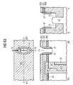
- FIG. 2B illustrates a cross-section of the transistor in a direction perpendicular to the direction of FIG. 2A .
- a section across the fin region 11 of the active area i.e. a portion of the active area having a narrow width, the fin region being surrounded on three sides thereof by the gate electrode.
- the active area has the form of a ridge or a fin.
- the active area has a top side 11 a and two lateral sides 11 b, the length of the top side 11 a being smaller than the length of the lateral sides 11 b.
- the plate-like portions 851 of the gate electrode 851 are disposed along the lateral sides 11 b of the ridge, whereas the groove-like portion 852 of the gate electrode is disposed along the top side 11 a of the ridge.
- the gate electrode 85 is insulated from the fin region 11 by the gate dielectric 80 .
- the current path 15 is in a direction perpendicular to the plane depicted in FIG. 1B .
- the transistor body Due to the narrow width of the fin region, the transistor body can be fully depleted, so that the subthreshold slope of the transistor can be improved. As a consequence, an improved on-current/off-current ratio is obtained.
- the fin region can be locally thinned so that the width of the channel region is made smaller than the width of the first and second source/drain regions. As a consequence, the off-current of the transistor can be further improved with respect to the known transistor while the contact area of the source/drain regions is not decreased. As a result the contact resistance is not increased.
- the length L eff of the channel corresponds to the distance between first and second source/drain regions.
- the width of the channel corresponds to the width of the region the conductivity of which is controlled by the gate electrode.
- the height of the fin can be 20 to 100 nm and the fin width can be less than 35 nm.
- the transistor of the present invention provides an improved on-current in comparison with known transistors, since the width of the channel is increased whereby the resistance is reduced. Moreover, the transistor exhibits a larger slope of the subthreshold characteristics and a remarkably reduced body effect. Thereby, the on-current is further increased.
- the transistor additionally provides an improved off-current due to its larger channel length and the larger slope of its subthreshold characteristics, in comparison to a known transistor.
- the transistor illustrated in FIGS. 2A and 2B combines an improved on-current with a decreased off-current.
- FIG. 2C illustrates a modification of the transistor structure illustrated in FIG. 2A .
- the first source/drain region includes a heavily doped portion 121 ′′ and a lightly doped region 121 ′.
- the lightly doped region 121 ′ extends to the same depth as the second source/drain region 122 .
- the electrical field can be reduced. Accordingly, a junction leakage current can be reduced.
- the leakage current corresponds to the current flowing from the storage capacitor to the second source/drain region or the silicon body when the gate electrode is not addressed. Since especially the electric fields at the first source/drain region—channel junction highly influence the leakage current, it is advantageous to reduce the electric field at the first source/drain region—channel junction. By reducing the leakage current, the retention time, i.e., the time during which an information is recognizably stored in the memory cell, can be increased.
- first and second source/drain regions in particular, the arrangement illustrated in FIG. 2C in which the first source/drain region 121 includes a lightly and a heavily doped portion and the lightly doped portion 121 ′ extends to the same depth as the second source/drain region 122 is highly advantageous.
- the second source/drain region 122 includes a lightly and a heavily doped portion wherein the lightly doped region is arranged between the heavily doped region and the channel region.
- the first and second source/drain regions comprising lightly and heavily doped portions can be arranged in a symmetric manner.
- the lower side of the lightly doped first source/drain region 121 ′ is disposed beneath the lower edge of the groove portion 852 of the gate electrode or than the top side of the fin region.
- the effective width of the first source/drain region can be remarkably increased. Since this width mainly determines an on-current, the on-current characteristics of the transistor are further improved.
- the heavily doped first source/drain region 121 which will later be connected with the storage capacitor is shielded from the gate electrode by the thick spacer 86 ′. Accordingly, the electric field at the junction, which is connected with the storage load will be reduced. As a consequence, the retention time will further be increased.
- the plate-like portions 851 can extend to a depth of 20 to 100 nm measured from the bottom portion of the groove region of the gate electrode.
- a first hard mask layer stack includes a silicon dioxide layer, a polysilicon (polycrystalline silicon) layer, a silicon dioxide layer as well as a polysilicon layer on top.
- the first hard mask layer stack can include a silicon nitride layer, a silicon dioxide layer and a polysilicon layer. In either cases it is important, that the first hard mask layer stack includes a polysilicon layer as the top most layer which will not be attacked by an etching process for etching silicon dioxide.
- a second hard mask layer stack comprising a carbon layer may provided on the surface of the first hard mask layer stack.
- the gate electrode 85 is formed in a gate groove formed in the semiconductor substrate 1 , and the plate-like portions 851 only extend slightly deeper into the substrate than the groove portion 852 .
- the plate-like portions 851 extend to a depth up to approximately 5 to 25 nm measured from the bottom portion of the groove portion of the gate electrode.
- the region which is adjacent to the gate electrode is not narrowed with respect to the active area, which is defined by forming the isolation trenches 2 . Accordingly, when applying a typical gate voltage, the channel will not be fully depleted. Nevertheless, as can in particular be taken from FIG.
- the resulting transistor has an increased channel width in comparison with a conventional recessed channel transistor.
- the first and second source/drain regions 121 , 122 can extend to a depth which is deeper than the depth, which is indicated in this Figure. In particular, they can extend to below the bottom of the gate groove 73 .
- the transistor illustrated in FIGS. 2D and 2E will also be referred to as an EUD (“extended u-groove device”)
- the process of providing a gate electrode includes the process of defining a gate groove in the semiconductor substrate so that finally a gate groove extends in the active area from the surface of the semiconductor substrate in a direction perpendicular to the surface of the semiconductor substrate to a first depth.
- the process of defining a gate groove includes a selective etching process which selectively etches the substrate material with respect to the isolating material of the isolation trenches. Thereafter, a pocket is defined in each of the isolation trenches at a position adjacent to the groove so that the two pockets will be connected with the groove and the groove is disposed between the two pockets, the two pockets extending to a second depth larger than the first depth.
- a gate insulating material is provided at an interface between the active area and the groove and at an interface between the active area and the pockets, and a gate electrode material is deposited so as to fill the groove and the two pockets.
- a first hard mask layer stack can be provided on the surface of the semiconductor substrate 1 or on a sacrifical silicon dioxide layer which is deposited on the surface of the semiconductor substrate.
- the first hard mask layer stack includes at least one layer of a material which is different from the material of the semiconductor substrate.
- a second hard mask layer stack can be provided on the surface of the first hard mask layer stack, the second hard mask layer stack comprising a carbon layer.
- the process for etching a gate groove in a substrate is an etching process which etches semiconductor material selectively with respect to the isolating material of the isolation trenches.
- the first hard mask layer stack includes a polysilicon layer as the top most layer.
- the first hard mask layer stack may include any of the following combinations: polysilicon layer/silicon dioxide layer/polysilicon layer (optional), silicon nitride layer/silicon dioxide layer/polysilicon layer (optional) and polysilicon layer/silicon nitride layer.
- the carbon hard mask is formed of a carbon film, which may be deposited, by physical vapor deposition or chemical vapour deposition.
- the carbon film can be made of amorphous carbon, which may optionally include hydrogen.
- the aspect ratio being limited to a certain value.
- a resist layer having a thickness of 100 to 200 nm is taken, a desired selectivity of an etching process cannot be obtained.
- a carbon hard mask which includes a carbon layer having a thickness of 200 to 300 nm and a silicon oxide nitride layer having a thickness of approximately 50 to 70 nm.
- the SiON layer is taken as a hard layer which is patterned.
- the patterned SiON layer is taken as a hard mask.
- the hard mask layer made of carbon is highly advantageous, because it can easily be etched using an O 2 -Plasma for example.
- the transistor which is manufactured by the method of the present invention advantageously includes sidewalls spacers 86 as is for example illustrated in FIG. 2A .
- the sidewall spacers 86 are provided at an interface between the gate electrode 85 and the first and second source/drain regions 121 , 122 so as to effectively insulate the gate electrode from the first and second source/drain regions.
- the sidewall spacers 86 have a larger thickness than the gate dielectric layer 88 and, hence, effectively shield the potential applied to the gate electrode 85 from the neighbouring first and second source/drain regions 121 , 122 .
- FIG. 2F illustrates an EUD in which the first and second source/drain regions 121 , 122 extend to a deeper depth than it is illustrated in FIG. 2D .
- a spacer is provided at a boundary between the gate electrode 85 and the first and second source/drain regions 121 , 122 so as to electrically isolate the gate electrode 85 from the first and second source/drain regions 121 , 122 .
- the gate groove is formed and a spacer made from a sacrificial material is provided, this spacer being replaced by a permanent spacer such as an SiO 2 spacer at a later process process.
- a permanent spacer such as an SiO 2 spacer
- the sacrificial spacer is formed at the position at which the permanent spacer is to be formed, in particular, at a position separating the gate electrode from the first and second source/drain regions.
- a sacrificial spacer is provided on the sidewalls of the first opening.
- the substrate material is isotropically etched and, in a following process, the sacrificial spacer is removed.
- the diameter of the groove formed in the substrate can be reduced with respect to the diameter of the first opening in the first hard mask layer stack.
- the critical dimension (“CD”) can further be reduced.
- the peripheral gate dielectric layer and the peripheral polysilicon layer can be formed, and then the array transistor is completed, followed by the deposition of the layer stack for forming the peripheral gate electrode as well as the word lines of the memory cell array.
- the peripheral gate dielectric and the peripheral polysilicon layer can advantageously be taken as part of the first hard mask layer stack for forming the array transistor. This embodiment is advantageous since the hard mask layer stack and the layers of the peripheral gate electrode can be formed by common deposition process.
- the array transistor can be formed, followed by the process for forming the peripheral gate dielectric layer and the process for forming the layer stacks for forming the peripheral gate electrode as well as the word lines of the array.
- This embodiment is advantageous, since the peripheral gate dielectric is not affected by the process process for forming the array transistor.
- the present invention provides a method for manufacturing a memory cell array comprising bitlines for electrically connecting the second source/drain region with a corresponding bit line.
- a hard mask layer stack comprising a silicon dioxide layer, a polysilicon layer and a silicon dioxide layer
- a special method for forming the bitline contacts can be used.
- the first hard mask layer stacks includes a silicon nitride and a silicon dioxide layer, a capacitive coupling between neighbouring word lines can advantageously be avoided whereby a crosstalking effect is reduced.
- gate dielectric layer or a gate insulating layer such as, in particular, a gate oxide.
- any other suitable dielectric material can be used as gate dielectric.
- FIGS. 3 to 33 illustrate a first embodiment of the present invention.
- a memory cell incorporating the transistor comprising a spacer which is made of silicon dioxide is provided.
- FIG. 3A illustrates a plan view on part of a memory cell array after forming the storage capacitors and after defining the active areas 12 .
- the active areas are formed as segments of stripes, two segments of active areas 12 in one row being insulated from each other by the trench top oxide 34 which is formed above a corresponding trench capacitor. Adjacent stripes of active areas 12 of different rows are spaced apart, isolation trenches being disposed between neighbouring rows, the isolation trenches being filled with an isolating material.
- the segments of the active areas 12 are arranged in a checkerboard manner, so that the segments of adjacent rows are arranged in a staggered manner. To be more specific, the segments of adjacent rows are offset by half of the cell pitch, in particular, 2 F.
- FIG. 3B A cross-section of the array illustrated in FIG. 3A between I and I is illustrated in FIG. 3B .
- trench capacitors 3 are provided so as to extend in the semiconductor substrate 1 , in particular, a silicon substrate.
- the trench capacitor 3 includes an inner electrode 31 , a capacitor dielectric 312 which is disposed between the inner electrode 31 and the counter electrode 313 .
- an isolation collar 32 is provided, as is conventional in the art.
- a polysilicon filling 31 is provided so as to accomplish an electrical contact between the inner capacitor electrode 31 and the buried strap window 33 which is formed above the isolation collar.
- a trench top oxide layer 34 is provided above the polysilicon filling 311 .
- the total thickness of the top oxide layer 34 can be approximately 30 nm, wherein the top oxide layer 34 preferably projects from the substrate surface 10 by approximately 15 nm so that the buried strap window 33 is disposed close to the substrate surface 10 .
- Reference numeral 21 denotes the bottom portion of the isolation trenches 2 which are formed in a cross-section parallel to the depicted cross-section.
- the formation of the trench capacitor 3 is generally known and the description thereof is omitted, for the sake of convenience.
- the trench capacitor includes a buried strap, so as to accomplish an electrical contact between the inner capacitor electrode 31 and the first source/drain portion of the transistor to be formed.
- the dopants of the polysilicon filling 311 diffuse into the substrate portion so as to form the buried strap out diffusion portion 331 .
- isolation trenches 2 for laterally confining the active areas 12 are etched and filled with an isolating material as is common.
- the isolation trenches 2 are filled with a first silicon dioxide layer, a silicon nitride liner and a silicon dioxide filling.
- a first and a second hard mask layer stacks 4 are deposited.
- a silicon nitride layer 41 having a thickness of approximately 10 nm, a silicon dioxide layer 42 having a thickness of approximately 120 nm, and a polysilicon layer 43 having a thickness of 50 nm are deposited.
- a carbon hard mask layer 44 having a thickness of about 180 nm and a silicon oxynitride layer 45 having a thickness of 60 nm are deposited.
- the silicon oxynitride (SiON) layer 45 acts as a hard layer for patterning the carbon layer 44 .
- the SiON layer 45 is an antireflective coating.
- a sacrificial SiO 2 layer may be provided between the substrate surface 10 and the silicon nitride layer 41 . The resulting structure is illustrated in FIG. 4 .
- openings are formed in the SiON layer 45 .
- the openings formed in the SiON layer 45 are formed by a tapered etching process, so that the diameter of the openings at a bottom portion thereof is smaller than the diameter at a top portion of the SiON layer.
- the openings are formed so that they have an oval shape, wherein the ratio between the longer side to the smaller side is approximately 2:1,2:
- the diameter of the opening at the bottom portion of the SiON layer 45 can be 50 to 300 nm.
- the resulting structure is illustrated in FIG. 5 .
- the carbon hard mask 44 is etched. Thereafter the polysilicon layer 43 and the silicon dioxide layer 42 are etched by a selective etching process which stops on the silicon nitride layer 41 .
- the resulting structure is illustrated in FIG. 6 , wherein in the top portion of FIG. 6 a plan view is illustrated. As can be seen, openings 46 are formed in the SiON layer 45 .
- the lower portion of FIG. 6 illustrates a cross-sectional view between I and I in the top portion. As can be seen from the lower portion, the openings 46 extend to the silicon nitride layer 41 .
- Silicon nitride 41 is etched selectively with respect to silicon and silicon dioxide. Thereafter, an etching process is performed so as to simultaneously etch silicon dioxide and silicon. In particular, approximately 15 to 60 nm Si are etched by this etching process. As a consequence, the opening 46 extends into the silicon substrate 1 . Moreover the upper portion of the isolation trenches 2 in a section which is perpendicular to the one depicted in FIG. 7 is etched as well.
- the SiON layer as well as the carbon hard mask layer 44 are removed.
- the carbon hard mask can be etched in an O 2 plasma. The resulting structure is illustrated in FIG. 7 .
- FIG. 7 illustrates a plan view on the resulting structure.
- openings 46 are formed in the polysilicon layer 43 .
- the silicon substrate material 1 of the active areas 12 is not covered.
- Isolation trenches are disposed adjacent to the active area 12 , the isolation trenches 2 not being covered in the opening.
- a cross-sectional view of the structure is illustrated in the lower portion of FIG. 7 .
- the opening 46 extends into the silicon substrate 1 .
- the opening 46 can extend into the substrate approximately 15 nm to 60 nm below the surface 10 thereof so as to form a gate groove 73 .
- a silicon nitride spacer 47 is formed.
- a silicon nitride layer having a thickness of approximately 0,3 F is conformally deposited followed by an anisotropic etching process, so as to form a spacer 47 .
- an etching process for etching the silicon dioxide material of the isolation trenches 2 is performed. In particular, about 100 nm SiO 2 are etched. The resulting structure is illustrated in FIG. 8 .
- FIG. 8A illustrates a plan view on the resulting structure.
- openings 46 are formed in the polysilicon layer 43 , the openings being enclosed by an annular silicon nitride layer 47 .
- isolation trenches 2 are provided on either sides of the active areas 12 .
- a cross-sectional view of the resulting structure is illustrated in the lower portion of FIG. 8A . This cross-sectional view is taken between I and I as can be seen from the top portion of FIG. 8A .
- a silicon nitride spacer 47 is disposed on either sides of the openings 46 .
- FIG. 8B illustrates a cross-sectional view which is taken between II and II as can be taken from FIG. 8A .
- pocket structures 74 which extend in the isolation trenches 2 have been formed by the oxide etching process.
- the silicon nitride spacer 47 is disposed at the upper portion of the openings 46 .
- the active area 12 is thinned by performing an isotropic silicon etching process.
- the active area is thinned by 10 to 20 nm. Accordingly, the resulting width of the active area amounts to approximately less than 35 nm.
- a gate dielectric layer 88 is deposited, for example by performing a ISSG (in-situ steam generated) oxidation process. The resulting structure is illustrated in FIG. 9 .
- FIG. 9 illustrates a plan view on the resulting structure.
- the active area 12 now is thinned with respect to the foregoing Figures.
- the whole surface area is covered by a silicon dioxide layer 88 , the position of the spacer 47 being indicated in the upper portion of FIG. 9 .
- the lower portion of FIG. 9 illustrates a cross-sectional view between I and I.
- the gate dielectric layer 88 is conformally deposited on the whole substrate surface.
- FIG. 10 illustrates a cross-sectional view between II and II as can be taken from the upper portion of FIG. 9A .
- the active area 12 now includes a thinned portion 125 .
- the silicon dioxide layer 88 is conformally formed on the whole surface.
- Extended pocket structures 74 ′ have been formed by the silicon etching process.
- a sacrificial silicon nitride layer having a thickness of approximately 80 nm is deposited. Thereafter, the silicon nitride layer is recessed by etching approximately 100 nm. As a consequence, a silicon nitride filling 49 is provided so as to fill the remaining opening 46 which has been formed by the former process. Then, the SiO 2 layer 88 and the polysilicon layer 43 are removed by generally known methods. As a result, the silicon nitride spacer 47 and the silicon nitride filling 49 extend to a height of approximately 70 nm or higher measured from the top portion of the silicon nitride layer 41 .
- FIG. 11A illustrates a cross-sectional view between I and I as can be seen from FIG. 9 , for example.
- FIG. 11B illustrates a cross-sectional view which is taken between II and II. As can be seen, in a cross-section perpendicular to the cross-section illustrate in FIG. 11A the opening 46 is filled with the silicon nitride spacer 47 as well as the silicon nitride filling 49 .
- FIG. 12 An etching process for removing the silicon dioxide layer 42 is performed. By this etching process also a top portion of the gate dielectric layer 88 which is disposed between the silicon nitride spacer 47 and the silicon nitride filling 49 is removed.
- the resulting structure is illustrated in FIG. 12 , wherein the left part of FIG. 12 illustrates the cross-sectional view between I and I and the right part of FIG. 12 illustrates a cross-sectional view of the peripheral portion of the memory device between III and III as can for example be taken from FIG. 1 .
- FIG. 12 now the complete surface of the substrate is covered by the silicon nitride layer 41 , with the exception of those portions, in which the gate electrode is to be formed.
- a silicon dioxide layer 54 having a thickness of 4 nm is formed as a layer for protecting the silicon nitride layer 41 .
- the silicon dioxide layer 54 can be formed by an ISSG oxidation process.
- the resulting structure is illustrated in FIG. 13 . As can be seen, now, the whole surface is covered by a silicon dioxide layer 54 .
- a resist material 35 is provided on the peripheral portion of the memory device leaving the array portion uncovered. Moreover, implantation process for providing the first and second source/drain regions 121 , 122 are performed. The resulting structure is illustrated in FIG. 14 . As can be seen from FIG. 14 , now the peripheral portion between III and III is covered by the resist layer 35 and the first and second source-drain regions 121 , 122 are formed.
- the deglazing process is performed so as to remove the silicon dioxide layer 54 from the array portion. Thereafter, the resist material 35 is removed from the peripheral portion. As a consequence, the peripheral portion remains protected by the silicon dioxide layer 54 , whereas in the array portion, the surface is covered by the silicon nitride layer 41 .
- the resulting structure is illustrated in FIG. 15 .
- An etching process with hot phosphoric acid is performed so as to selectively etch silicon nitride with respect to silicon dioxide.
- the silicon nitride layer 41 is removed from the array portion.
- the silicon nitride spacers 47 and the silicon nitride filling 49 in the middle of the formed opening are completely etched. Since this etching process is selective with respect to silicon dioxide, the peripheral portion is not etched by this etching process.
- the resulting structure is illustrated in FIG. 16 .
- the silicon dioxide layer includes the gate dielectric layer 88 and the silicon dioxide spacer 36 which is formed having a thickness of approximately 15 to 20 nm, thereby consuming 9 to 12 nm Si.
- a nitride etching process with hot phosphoric acid is performed. Thereby the silicon nitride layer 41 is removed from the peripheral portion. The resulting structure is illustrated in FIG. 18 .
- an implantation process for providing the doped regions of the peripheral transistor can be performed. Then, the sacrificial SiO 2 , if present, is removed.
- FIG. 19 The resulting structure is illustrated in FIG. 19 .
- the gate groove now is filled with polysilicon material.
- SiO 2 layers 36 , 29 are illustrated above the capacitor trench, it is obvious to the person skilled in the art, that—depending on the process conditions under which the SiO 2 layers have been formed, these layers are not formed as continuous layers which cover the capacitor trench. To be more specific, if the SiO 2 layers 36 , 29 have been formed by thermal oxidation, they are not formed above the trench top oxide 34 which is filled in the capacitor trenches.
- FIG. 19B which illustrates a cross-sectional view between II and II, also in a cross-section perpendicular to the one depicted in FIG. 19A , the gate groove is filled with polysilicon material.
- the layers for forming the gate stack are deposited.
- a polysilicon layer 55 , a tungsten layer 82 and a silicon nitride layer 56 are deposited as is conventional in the art.
- the resulting structure is illustrated in FIG. 20 .
- the layer stack for forming the gate electrode is patterned so as to form the word lines.
- the layers are etched using a resist pattern which has been formed by using a mask having a lines/spaces pattern.
- the layer stack is etched.
- the end point of the process of etching the polysilicon layer 55 is detected by end point detection so as to stop on the polysilicon material 48 .
- FIG. 21 As can be seen, active word lines 8 a and passing word lines 8 b have been formed in the array portion, whereas a peripheral gate electrode 8 c has been formed in the peripheral portion between III and III.
- FIG. 21 a slight misalignment of the word lines 8 a, 8 b with respect to the gate electrodes is illustrated. As will be apparent from the following description, such a misalignment will not cause unwanted shorts.
- a process of etching the polysilicon layer 55 is performed.
- the process of etching the polysilicon layer 55 can be an overetching process which also etches the polysilicon layer 48 .
- an additional etching process for etching the polysilicon layer 48 can be performed.
- the resulting structure after etching the polysilicon material is illustrated in FIG. 22 .
- the polysilicon material now is removed in an upper portion of the gate groove 73 .
- this exposed portion of the gate groove 73 can be filled with silicon dioxide.
- silicon dioxide about 30 nm SiO 2 are deposited by using a CVD process using TEOS (tetraethyl ortho silicate) as a starting gas.
- TEOS tetraethyl ortho silicate
- the silicon dioxide layer is etched by approximately 40 nm.
- the SiO 2 filling 37 is formed at the bottom portion of the gate groove.
- the gate dielectric layer 29 is also etched. The resulting structure after this optional process is illustrated in FIG. 23 .
- an oxidation process so as to form a sidewall oxide 38 having a thickness of approximately 7 nm is formed by generally known methods.
- the resulting structure is illustrated in FIG. 24 .
- bit line contacts to the second source/drain region 122 will be described.
- the process process are already known and are merely described as an example.
- the bit line contacts can as well be formed by any other suitable process, in particular, by self aligned contact formation.
- a silicon dioxide layer 57 having a thickness of approximately (0.3 ⁇ F) is deposited by a generally known method, for example, the TEOS method.
- this process can be performed so as to fill the upper portion of the gate groove with silicon dioxide.
- the resulting structure is illustrated in FIG. 25 .
- bit line contact plug 95 is formed by conventional methods.
- an undoped polysilicon layer 93 is deposited.
- a CMP process is performed, followed by a CVD (chemical vapour deposition) process for forming a silicon nitride layer 94 .
- the contact plugs 95 are photolithographically defined using a bit line contact mask and etching the polysilicon layer 93 and the silicon nitride layer 94 .
- the photoresist material is removed from the surface.
- FIG. 26 As can be seen, bit line contact plugs 95 are formed at a position above the second source/drain region 122 .
- a deglazing process is performed so as to remove part of the superficial silicon dioxide layer. Thereafter, a wet etching process for etching silicon nitride 94 is performed. Then, an anisotropic etching process is performed so as to remove the horizontal portions of the silicon dioxide layer 57 .
- the resulting structure is illustrated in FIG. 27 .
- a contact plug 95 made of polysilicon is formed above the second source/drain region 122 .
- the first source/drain region 121 is not covered.
- the silicon dioxide layer 57 is removed from the horizontal surface portion.
- a silicon dioxide layer 96 is deposited on the whole surface. Thereafter implantation process for implanting the lightly doped portions in the peripheral portion of the memory device are performed. In addition, the p- and n-doped portions are provided by ion implantation process. The resulting structure is illustrated in FIG. 28 . As can be seen, the whole surface is covered by a thin silicon dioxide layer 96 .
- a silicon nitride layer 97 having a thickness of 12 nm is deposited by a LPCVD (low pressure CVD) method. Thereafter, a BPSG layer is deposited. The BPSG layer 971 is annealed and a CMP process is performed so as to remove the oxide layer 96 .
- the resulting structure is illustrated in FIG. 29 . As can be seen from the left part of FIG. 29 , illustrating a cross-sectional view of the array portion, the polysilicon material 93 of the bit line contact plug 95 now is uncovered.
- the polysilicon material 93 is removed by a conventional etching process. Thereafter, the spacer oxide 96 which has been directly adjacent to the bit line contact plug 95 is etched. As a consequence, a bit line contact opening 90 is formed in the surface. Thereafter, an ion implantation process can be performed so as to provide a doped pocket 133 forming part of the second source/drain region. The resulting structure is illustrated in FIG. 30 . As can be seen, the bit line contact opening 90 is in contact with the second source/drain region 122 .
- An opening 27 is formed in the peripheral portion so as to contact the peripheral gate electrode 8 c.
- This peripheral gate electrode contact opening 27 is formed by conventional methods, i.e., by photolithographically defining the corresponding opening. The resulting structure is illustrated in FIG. 31 .
- peripheral contacts 26 are formed in the peripheral portion by photolithographically patterning and etching the openings 28 .
- the openings 27 and 28 can be simultaneously formed by one common etching process.
- implantation process for reducing the contact resistance are performed. The resulting structure is illustrated in FIG. 32 . As can be seen, in the peripheral portion a peripheral gate electrode opening 72 and peripheral contact openings 28 have been formed.
- the electric conductive material is filled in the patterned openings 27 , 28 and 90 .
- a Ti layer 98 and a TiN layer 981 are formed, for example, by sputtering.
- a tungsten layer 99 is deposited, for example by a MOCVD (metal organic chemical vapour deposition) or a sputter method.
- a CMP (chemical mechanical polishing) process is performed.
- bitlines 9 are formed by a commonly known method.
- FIG. 33 The resulting structure is illustrated in FIG. 33 .
- a memory cell is formed comprising a storage capacitor 3 , which is connected with the first source/drain region 121 of the transistor.
- the transistor further includes a second source/drain region 122 and a gate electrode 48 which is insulated from the channel by a gate dielectric layer 88 .
- the gate electrode 48 is connected with the corresponding word line 8 a comprising a polysilicon layer 55 and a tungsten layer 82 .
- the gate electrode 48 is insulated from the first and second source/drain regions 121 , 122 by the silicon dioxide spacer 36 and the gate dielectric layer 88 , so that an electrical field of the gate electrode can be reduced.
- the second source/drain region 122 is connected with a bit line 9 via a bit line contact 901 .
- bit lines 9 extend in a direction which is perpendicular with respect to the direction of the word lines 8 a, 8 b.
- the peripheral portion is illustrated, the gate electrode 8 c of the peripheral portion being connected via a peripheral gate electrode contact 25 and peripheral contacts 26 being provided.
- the first and second source/drain portions 121 and 122 extend to a larger depth then the gate electrode 48 .
- the channel connecting the first and second source/drain regions mainly has horizontal components with respect to a substrate surface.
- the active area is enclosed at three sides thereof by the gate electrode 48 .
- the fin region in which the active are has the shape of a ridge, is thinned so that during the operation of the array transistor, the channel can be fully depleted.
- the second embodiment refers to a method of manufacturing a memory device wherein part of the array portion and part of the peripheral portion are processed by the same process process.
- the first hard mask layer stack for forming the gate electrodes includes a first polysilicon layer, a silicon dioxide layer and optionally a second hard mask layer.
- the second hard mask layer stack includes a carbon layer.
- the first polysilicon layer covering the array portion also acts as a mask for masking the peripheral portion during the manufacture of transistors in the array portion.
- the array transistor is formed as a recessed channel transistor in which the plate-like portions of the gate electrode extend deeper into the substrate than the groove region of the gate electrode, the difference of depth not being large.
- the isolation trenches 2 in the array portion extend to a deeper depth than the isolation trenches 23 in the peripheral portion.
- the isolation trenches 2 in the array portion can extend to any suitable depth in comparison with the isolation trenches 23 in the peripheral portion.
- the isolation trenches 2 in the array portion extend to the same depth as the isolation trenches 23 in the peripheral portion.
- a sacrificial oxide layer 24 is grown on the whole substrate surface. Thereafter, lithographic process for defining the portions to be doped are performed. Next, the well implants are performed as is usual.
- FIG. 34 illustrates the cross-sectional view of the resulting structure.
- the cross-sectional view between IV and IV illustrates a view parallel to the direction of the active areas 12 , as can as well be taken from FIG. 3A .
- the right hand portion of FIG. 34 illustrates the cross-sectional view between V and V which is taken perpendicularly with respect to the direction of the active areas, as can as well be taken from FIG. 3A .
- the cross-sectional view between VI and VI illustrates a cross-sectional view of the peripheral portion, as can be taken from FIG. 1 .
- a doped substrate portion 124 is provided at the substrate surface 10 in the array portion, whereas in the peripheral portion no doped region is provided.
- the isolation trenches 2 in the array portion extend to a predetermined depth, the bottom portion of the isolation trenches being indicated by the broken line 21 in the cross-sectional view between IV and IV.
- a polysilicon liner 200 is deposited by generally known methods, the polysilicon liner having a thickness of approximately 20 to 60 nm.
- FIG. 35 The resulting structure is illustrated in FIG. 35 .
- the whole substrate surface now is covered by the polysilicon liner 200 .
- a silicon dioxide layer 201 is deposited by a generally known method.
- the silicon dioxide layer 201 has a thickness of approximately 100 nm resulting in a planar substrate surface.
- the resulting structure is illustrated in FIG. 36 .
- a polysilicon layer 202 having a thickness of approximately 60 to 120 nm is provided by a general known method so as to cover the whole substrate surface.
- a carbon hard mask layer 203 having a thickness of approximately 150 to 300 nm is deposited by generally known methods over the whole substrate surface, followed by a SiON layer 204 having a thickness of approximately 50 to 100 nm.
- the resulting structure is illustrated in FIG. 38 .
- Openings are formed in the SiON layer 204 and the carbon hard mask 203 .
- the openings to be formed have an oval shape having two different diameters in a direction parallel to the active area direction and in the direction perpendicular thereto.
- a tapered etching process is performed so as to etch the SiON layer 204 , followed by an etching process for etching the carbon hard mask layer 203 , this etching process not being tapered.
- the resulting structure is illustrated in FIG. 39 .
- the opening 7 is formed in the carbon hard mask layer 203 and the SiON layer 204 .
- the opening 7 has a smaller diameter in the cross-sectional view between IV and IV than in the cross-sectional view between V and V.
- the diameter of the opening 7 between V and V is larger than the width of the active area 12 .
- the peripheral portion is not affected by this etching process.
- the polysilicon hard mask layer 202 is etched, followed by an etching process for etching silicon dioxide.
- the resulting structure is illustrated in FIG. 40 .
- the opening 7 is etched, stopping on the polysilicon layer 200 .
- the opening 7 is etched stopping on the polysilicon layer 200 whereas the peripheral portion is not affected.
- the SiON layer 204 , the carbon hard mask layer 203 and the polysilicon layer 202 are removed, leaving the structure covered with the silicon dioxide layer 201 . Thereafter, an etching process for etching polysilicon is performed, followed by a short silicon dioxide, breakthrough etching process. By this etching process the silicon dioxide layer 24 is opened. Thereafter, an etching process of etching silicon is performed, resulting in a silicon groove 73 which is formed in the silicon substrate material. The resulting structure is illustrated in FIG. 41 .
- the silicon groove 73 extends to a depth so that the bottom side of the groove 73 is disposed beneath the bottom side of the doped portion 124 .
- the SiON, carbon and polysilicon hard mask layers 204 , 203 , 202 are also removed from the peripheral portion.
- the resulting surface is covered with silicon dioxide, wherein the portion of the active area 12 which is opened by the silicon groove 73 is uncovered.
- an isotropic silicon etching process is performed so as to laterally remove 10 to 20 nm silicon material.
- the silicon groove 73 is widened, whereas the groove 73 is deepened in the cross-section view between V and V.
- the position of the silicon groove before this etching process is indicated by the broken lines.
- the silicon dioxide layer 301 laterally projects from the side walls of the groove.
- the resulting plan view is illustrated in the upper portion of FIG. 42 .
- a bottle structure 205 is formed.
- an additional sacrificial silicon dioxide layer is formed.
- an isotropic etching process in HF (hydrofluoric acid) is performed.
- the bottle structure is removed, and pockets 74 are formed in the isolation trenches 2 .
- the pockets 74 extend deeper in the isolation trenches than the silicon groove 73 . Nevertheless, the difference between the depth of the pocket structures 74 and the silicon groove 73 is only small.
- this etching process is performed so as to etch about 10 to 20 nm, depending on the minimal structural feature size F of the technology used.
- FIG. 43 The resulting structure is illustrated in FIG. 43 .
- the bottle structure 205 now is removed in this cross-sectional view.
- pocket structures 74 are formed.
- the pocket structures 74 only slightly project with respect to the surface of the active area 12 .
- the plan view on the resulting structure is illustrated in the upper portion of FIG. 43 .
- the gate dielectric layer 88 has a thickness of 2 to 6 nm, depending on the technology used.
- FIG. 44 The resulting structure is illustrated in FIG. 44 , wherein the upper portion of FIG. 44 illustrates a plan view, whereas the lower portion of FIG. 44 illustrates the respective cross-sectional views. As can be taken from the cross-sectional views between IV and IV and between V and V, the surface of the gate groove 73 now is covered with the gate dielectric layer 88 .
- a polysilicon layer 206 is deposited, followed by an optional CMP process for planarizing the surface and an isotropic etching process for etching the polysilicon layer. As a result, the lower portion of the silicon groove 73 is filled with the polysilicon material 206 as can also be taken from FIG. 45 .
- a silicon dioxide spacer 36 is formed in the upper portion of the silicon groove 73 .
- a silicon dioxide layer is deposited by generally known methods, followed by an anisotropic etching process for removing the horizontal portions of the deposited silicon dioxide layer.
- the silicon dioxide spacer 36 is formed.
- FIG. 46 illustrates the resulting structure.
- the upper portion of FIG. 46 illustrates a plan view on the resulting structure, whereas the lower portion of FIG. 46 illustrates the corresponding cross-sectional views.
- the silicon dioxide spacer 36 is formed on the side walls of the silicon groove 73 in the upper portion thereof.
- the recess 73 formed in the semiconductor substrate is filled by a further polysilicon filling 207 and an etching process for partially etching this additional filling 207 is performed.
- the resulting structure after this optional process is illustrated in FIG. 47 .
- the height of the surface of the additional polysilicon filling 207 approximately corresponds to the upper edge of the polysilicon liner 200 .
- FIG. 48 An anisotropic etching process for removing the SiO 2 layer is performed. As a consequence, the SiO 2 layer 201 is horizontally etched. The resulting structure is illustrated in FIG. 48 . As can be seen, in the cross-sectional view between VI and VI of the peripheral portion, the oxide spacer 2010 can be formed adjacent to the peripheral isolation trench 23 . In the array portion, the silicon dioxide layer 201 is completely removed leaving the SiO 2 spacer 36 in the silicon grooves 73 . The resulting plan view is illustrated in the upper portion of FIG. 48 .
- the array portion is covered by an etching mask. Then, the remaining portion of the silicon dioxide layer is removed and a polysilicon etching process is performed. Moreover, the sacrificial oxide layer 24 is removed. Thereafter, the resist is stripped from the array portion.
- FIG. 49 The resulting cross-sectional view of the peripheral portion is illustrated in FIG. 49 .
- substrate surface in the peripheral portion is uncovered. Since during the previous process the array portion has been covered with a suitable resist layer, the array portion has not been affected by the described process.
- etching process for removing the silicon dioxide layer is performed. Thereby, the silicon dioxide layer 24 is removed from the peripheral portion. Thereafter, a peripheral gate dielectric layer 29 is formed.
- the peripheral gate dielectric layer can have a thickness of 1 nm to 6 nm, depending on the structural feature size F.
- a polysilicon layer 208 having a thickness of 35 nm is deposited by generally known methods. The resulting structure is illustrated in FIG. 51 .
- the peripheral portion is covered with an etching mask, leaving the array portion uncovered. Thereafter, an etching process for etching the polysilicon layer 208 and an etching process for etching the silicon dioxide layer 29 from the array portion is performed. The mask covering the peripheral portion is removed. The resulting structure is illustrated in FIG. 52 . As can be taken from the cross-sectional view between VI and VI, the peripheral portion is not affected by the process. In the array portion, the polysilicon layer 208 as well as the peripheral gate dielectric layer 29 are removed.
- the peripheral portion as well as the array portion are processed by common process process.
- neither the array portion nor the peripheral portion are selectively masked with a corresponding resist material so that only one of the array portion or the peripheral portion is processed.
- an additional polysilicon layer 811 is deposited.
- the resulting structure is illustrated in FIG. 53 .
- the whole substrate surface now is covered by the polysilicon layer 2080 .
- the gate electrode can be formed of WSi.
- a silicon layer 811 , a WSi (tungsten silicide) layer 82 as well as a silicon nitride layer 81 a are deposited on the whole surface. The resulting structure is illustrated in FIG. 54 .
- the layer stack for forming the word lines and the peripheral gate electrode can be formed by any other method as is generally used in the art.
- the gate layer stack can be patterned using a mask having a lines/spacers pattern in the array portion so as to result in the structure illustrated in FIG. 59 .
- the structure illustrated in FIG. 54 can be obtained by a different method.
- a hard mask layer stack comprising a first polysilicon layer 200 is provided.
- a sacrificial layer 24 must be provided between the substrate surface 10 and the first polysilicon layer 200 .
- the process of forming a memory device can additionally be simplified, if the sacrificial oxide layer 24 and the polysilicon layer 200 form the peripheral gate dielectric layer and part of the layer stack for forming the peripheral gate electrode. Nevertheless, in this modification, special care has to be taken that the gate dielectric layer 29 and the first polysilicon layer 200 are not affected by the process for forming the transistor in the array portion.
- the well implantation process for defining the wells in the array portion are performed as has been described above.
- an ion implantation process for providing the doped portion 124 which will later define the first and second source/drain regions is performed.
- the resist material is removed from the whole surface.
- a silicon dioxide layer 29 acting as a peripheral gate dielectric 29 is deposited.
- the resulting structure is illustrated in FIG. 55 . As can be seen from FIG. 55 , the whole surface now is covered with the silicon dioxide layer 29 .
- FIG. 56 The resulting structure is illustrated in FIG. 56 .
- the whole surface now is covered with the polysilicon layer 200 .
- the polysilicon material 206 , 207 is filled, the upper portion of the gate electrode being insulated from the doped portion 124 by a silicon dioxide spacer 36 .
- the polysilicon liner 200 is formed above the peripheral gate dielectric layer 29 .
- the array portion can be covered with a suitable mask, leaving the peripheral portion uncovered.
- an etching process to remove the silicon dioxide residuals from the peripheral portion is performed.
- a polysilicon layer 208 is deposited over the whole surface.
- the resulting structure is illustrated in FIG. 57 .
- the layers for forming the word lines and the peripheral gate electrodes are deposited by generally known methods.
- a silicon layer 811 as well as a WSi layer 82 can be deposited, followed by a silicon nitride layer 81 a.
- the resulting structure is illustrated in FIG. 58 .
- the layer stack for forming the word lines and the peripheral gate electrode can be formed by any other method as is generally used in the art.
- FIG. 59 The resulting structure is illustrated in FIG. 59 .
- a suitable mask for example a mask having a lines/spacers pattern
- the deposited layers for forming the word lines and the gate electrodes in the peripheral portion are patterned.
- the resulting structure is illustrated in FIG. 59 .
- an active word line 8 a as well as a passing word line 8 b are formed on the substrate surface.
- a peripheral gate electrode 8 c is formed which is insulated from the active portion of the support by the gate dielectric layer 29 .
- the gate electrode 85 is connected with a corresponding active word line 8 a.
- the transistor formed includes first and second source/drain regions 121 , 122 .
- a channel 14 is formed between the first and second source/drain regions.
- a current path 15 between the first and second source/drain regions includes vertical as well as horizontal components with respect to the substrate surface 10 .
- the first source/drain region 121 is connected with the storage electrode 31 of the storage capacitor 3 via a polysilicon filling 311 .
- the gate electrode 85 is insulated from the channel 14 by a gate dielectric layer 88 .
- a silicon dioxide spacer 36 is provided at the upper portion of the gate electrode for shielding the gate electrode from the first and second source/drain regions, thereby reducing a leakage current of the transistor.
- the illustrated structure can be completed by forming the bit line contacts for example by the process flow illustrated with reference to FIG. 24 to 33 .
- a silicon dioxide layer 38 can be optionally deposited as is illustrated in FIG. 60 .
- bit lines are formed so as to extend perpendicularly with respect to the word lines.
- the transistor in the array portion is formed as a FinFET, in which the gate electrode encloses the active area at three sides thereof, the gate electrode comprising two plate-like portions which extend to a deeper depth than according to the second embodiment of the present invention.
- the second embodiment includes an isotropic etching process for etching 10 to 20 nm SiO 2
- the second polysilicon layer 202 is not required for forming the array transistor according to the second embodiment, as is also illustrated with reference to FIG. 43 .
- the etching process for etching SiO 2 etches about 100 nm
- the second polysilicon hard mask layer 202 is required for implementing the third embodiment of the present invention.
- the processes which have been described with reference to FIG. 34 to 40 are performed. Nevertheless, the implantation process for providing the doped portion 124 which will later form the first and second source/drain regions is not conducted.
- an etching process which etches both, silicon and silicon dioxide, is performed. Thereby, the openings 7 are also formed in the polysilicon layer 200 as well as in the silicon dioxide layer formed above the substrate surface and the silicon dioxide material filled in the isolation trenches 2 .
- the resulting structure is illustrated in FIG. 61 .
- openings 73 are formed in the silicon substrate as well as in the layers formed above. Since the etching process which just has been performed, is unselective with respect to Si and SiO 2 , the opening 73 has a broader cross-section than the opening 73 illustrated in FIG. 41 , for example.
- the opening 73 extends in the substrate material as well as in the isolation trench 2 .
- the opening 73 can extend to a depth of 15 to 60 nm below the substrate surface 10 .
- the support portion which is illustrated between VI and VI has not been affected by these etching process.
- a polysilicon liner 200 , a SiO 2 layer 201 and a polysilicon layer 202 are formed on the substrate surface 10 in the peripheral portion.
- the openings 73 have an oval shape, wherein on either sides of the active area 12 , the isolation trenches 2 are not covered.
- a thin silicon dioxide liner can be deposited on the whole surface.
- a silicon nitride spacer is formed by generally known methods.
- a silicon nitride layer having a thickness of approximately 0.2 ⁇ F to 0.3 ⁇ F is conformally deposited.
- an anisotropic etching process for removing the horizontal portions of the silicon nitride layer is performed.
- the side walls of the opening 73 are covered with the silicon nitride spacer 47 .
- the resulting structure is illustrated in FIG. 62 .
- FIG. 63 An anisotropic etching process for etching silicon dioxide material selectively with respect to silicon is performed. Since the side walls of the opening 73 are protected by the silicon nitride spacer 47 , pocket structures 74 are formed in the isolation trenches 2 by this etching process. For example, by this etching process about 100 nm SiO 2 material are etched so that the bottom side of the pocket structures 74 is about 100 nm below the bottom side of the silicon nitride spacers 47 and about 150 nm below the surface 10 of the semiconductor substrate 1 . The resulting structure is illustrated in FIG. 63 . As can be seen from the cross-sectional view between IV and IV, parallel to the direction of the active areas, the grooves are slightly deepened, whereas in a cross-section perpendicular thereto the pocket structures 74 are formed.
- An isotropic Si etching process is performed so as to narrow the active area 12 .
- a narrowed fin region 11 is formed, and the pockets 74 ′ are extended.
- the resulting structure is illustrated in FIG. 64 .
- a silicon dioxide layer 88 acting a as a gate dielectric layer is deposited by generally known methods.
- the resulting structure is illustrated in FIG. 65 .
- a polysilicon layer is formed by generally known methods and then, the polysilicon layer is recessed.
- the surface of the polysilicon filling 206 which is formed in the gate groove 73 is disposed at the same height as the surface of the polysilicon liner 200 .
- the resulting structure is illustrated in FIG. 66 .
- the polysilicon filling 206 is disposed in the middle of the gate groove 73 .
- the whole surface is covered with a silicon dioxide layer 88 , with the exception of the polysilicon filling 206 which is disposed in the gate groove 73 .
- the groove 73 encloses the active area 12 at three sides thereof.
- FIG. 67 An etching process for etching silicon dioxide is performed, so that the gate dielectric layer 88 is removed from those portions which are not covered by the polysilicon filling 206 .
- the resulting structure is illustrated in FIG. 67 .
- the polysilicon layer 202 is uncovered.
- the silicon nitride spacer 47 is uncovered.
- the polysilicon layer 202 is uncovered.
- the plan view of the resulting structure is illustrated in the upper portion of FIG. 67 .
- a silicon nitride layer is deposited so as to completely fill the openings 73 .
- an anisotropic etching process is performed so as to remove the horizontal portions of the silicon nitride layer.
- the upper portions of the gate grooves 73 is filled with a silicon nitride filling 49 .
- the resulting structure is illustrated in FIG. 68 , illustrating the filled gate grooves 73 .
- the peripheral portion is masked by an appropriate mask leaving the array portion uncovered. Then, an etching process for etching polysilicon as well as an etching process for etching silicon dioxide are performed. As a consequence, the polysilicon layer 200 is uncovered in the array portion.
- the silicon nitride filling 49 projects from the gate grooves 73 . In particular, the silicon nitride filling 49 projects by approximately 100 to 200 nm with respect to the surface 10 of the silicon substrate.
- first and second source/drain regions 121 , 122 are formed in the upper portion of the silicon substrate 1 .
- the bottom side of the first and second source/drain regions 121 , 122 can be disposed beneath the bottom side of the gate electrode 85 .
- the bottom side of the first and second source/drain regions 121 , 122 can as well be disposed at the same height or above the bottom side of the gate electrode 85 .
- FIG. 71 An etching process for etching silicon nitride is performed. As a consequence, the projecting portions of the silicon nitride filling 49 are removed as well as the silicon nitride spacers 47 . The resulting structure is illustrated in FIG. 71 . As can be seen from the cross-sectional view between IV and IV, openings are formed between the gate dielectric layer 88 and the first and second source/drain regions 121 , 122 . As can be seen from the cross-sectional view between V and V, openings are formed between the polysilicon filling 206 and the isolating material of the isolation trenches 2 .
- a silicon dioxide layer having a thickness of at least 10 nm is deposited, in particular by a TEOS or a HDP (high density plasma) method as is conventional. Thereafter, an anisotropic etching process is performed so as to form the silicon dioxide spacer 36 in the openings formed in the substrate surface 10 . This etching process is performed so that an overetching of 5 to 10 nm is obtained. As a consequence, the silicon dioxide spacer 36 are formed as can be seen from FIG. 72 .
- the array portion is masked with a resist material leaving the peripheral portion uncovered. Thereafter, an etching process of etching silicon dioxide is performed, followed by a process of etching polysilicon. Thereafter, the resist material is removed from the array portion.
- the structure illustrated in FIG. 73 is obtained.
- the surface 10 of the silicon substrate is only covered with the sacrificial silicon dioxide layer 24 .
- a silicon dioxide etching process is performed so as to remove the silicon dioxide layer 24 , followed by a process of forming a peripheral gate dielectric 29 .
- FIG. 74 is obtained.
- a peripheral gate dielectric layer 29 is formed in the peripheral portion between VI and VI, whereas the remaining surface is covered with the silicon dioxide layer 29 .
- a polysilicon layer having a thickness of about 30 to 100 nm is deposited on the whole surface.
- a suitable resist layer is applied on the peripheral portion, masking the peripheral portion while leaving the array portion uncovered.
- an etching process for etching polysilicon is performed, followed by an etching process for etching silicon dioxide.
- the structure illustrated in FIG. 75 is obtained.
- a thick polysilicon layer 208 is present, whereas in the array portion, the thin polysilicon layer 200 is uncovered, with the silicon dioxide spacer 36 being uncovered at the portion of the gate electrode.
- a polysilicon layer having a thickness which is selected so that the final polysilicon layer thickness of the layer stack of about 40 to 100 nm is obtained is deposited by generally known method, followed by the usual gate electrode layer stack. Nevertheless, as is obvious to the person skilled in the art, the layer stack for forming the word lines and the peripheral gate electrode can be formed by any other method as is generally used in the art.
- FIG. 76 The resulting structure is illustrated in FIG. 76 , in which the whole surface is covered by the silicon nitride layer 81 a. Thereafter, the deposited layer stack is patterned using the mask having a lines/spacers pattern so as to obtain the structure illustrated in FIG. 77 .
- active and passing word lines 8 a, 8 b are provided on the surface.
- a peripheral gate electrode is formed in the peripheral portion between VI and VI.
- a gate electrode in which the polysilicon filling 206 is insulated from the first and second source/drain regions by a silicon dioxide spacer 36 is provided in the array portion between IV and IV.
- the gate electrode is disposed near the surface of the semiconductor substrate 1 , and the bottom side of the first and second source/drain regions 121 , 122 is disposed beneath the bottom side of the gate electrode 85 .
- the active region 12 includes a narrowed fin region 11 which is enclosed by the gate electrode at three sides thereof.
- the first hard mask layer stack for patterning the array transistor includes a silicon nitride layer and a silicon dioxide layer.
- a sacrificial oxide layer 24 may be provided between the substrate surface 10 and the silicon nitride layer.
- a polysilicon layer must be provided on the surface of the silicon dioxide layer of the first hard mask layer stack. If the transistor to be formed has pocket structures which do not extend to such a deep depth (EUD), the polysilicon layer is optional.
- EUD deep depth
- the second hard mask layer stack includes a carbon hard mask layer.
- the peripheral portion is masked with silicon nitride liner. After completing the array transistor, the peripheral portion is completed.
- the array transistor is formed with pockets that only slightly project with respect to the surface of the active area 12 .
- the transistor is implemented as a so called EUD.
- a silicon nitride liner 209 is deposited so as to cover the whole surface. The resulting structure is illustrated in FIG. 78 .
- the peripheral portion is covered with a silicon nitride liner 209 .
- the silicon nitride liner covers the active area, the isolation trenches as well as the trench top oxide 34 .
- a silicon dioxide layer is deposited, the silicon dioxide layer 201 having a thickness so as to planarize the whole surface.
- the resulting structure is illustrated in FIG. 79 .
- a planarized surface of the silicon dioxide layer 201 is provided.
- a silicon nitride liner 209 is provided instead of the polysilicon liner 200 which has been used according to the second embodiment of the present invention.
- a planarizing process such as a CMP process is performed so as to obtain a planarized surface.
- the recessing process which has been performed according to the description in connection with FIG. 47 is not performed.
- the structure illustrated in FIG. 80 is obtained.
- oval islands of polysilicon materials 207 are disposed in a silicon dioxide surface 201 .
- peripheral portion has not been changed by these processes, as can be taken from the cross-sectional view between VI and VI.
- a planarized surface is provided, with the polysilicon filling 207 extending to the surface of the silicon dioxide layer 201 .
- the array portion is masked with a suitable resist material, leaving the peripheral portion uncovered. Thereafter, an etching process for etching silicon dioxide 201 is performed, followed an etching process for etching silicon nitride 209 . These layers are removed from the peripheral portion, since the array portion is masked with the mask. Thereafter, the sacrificial oxide layer 24 is stripped from the peripheral portion and the mask is removed from the array portion. Thereafter, a process for depositing a peripheral gate dielectric layer 29 , in particular, a peripheral gate oxide layer, is performed. As can be seen from the structure illustrated in FIG. 81 , the gate dielectric layer 29 covers the peripheral portion between VI and VI as well as the array portion between IV and IV and V and V.
- a polysilicon layer 2080 nm is deposited over the whole surface. As a result, the structure illustrated in FIG. 82 is obtained. As can be seen, the peripheral portion as well as the array portion are covered by the thick polysilicon layer 2080 .
- the peripheral portion is covered with a suitable mask, leaving the array portion uncovered. Then, an etching process for etching polysilicon is performed. As a result, the structure illustrated in FIG. 83 is obtained.
- the substrate is covered with a polysilicon layer 2080
- the surface is covered with a peripheral gate dielectric layer 29 .
- the peripheral gate dielectric layer 29 is removed from the array portion and, optionally, a polysilicon layer 811 is deposited, followed by a tungsten layer 82 and a silicon nitride layer 81 a.
- the layer stack for forming the word lines and the peripheral gate electrode can be formed by any other method as is generally used in the art.
- FIG. 84 The resulting structure is illustrated in FIG. 84 .
- the tungsten layer 82 is formed on the thick polysilicon layer 2080 .
- the tungsten layer 82 is formed on the thin polysilicon layer 811 .
- a topography is generated between the array portion and the peripheral portion.
- a lithographic process using a mask having a lines/spacers pattern is performed, followed by an anisotropic etching process for etching the silicon nitride layer 81 a, the tungsten layer 82 as well as the polysilicon layers 2080 , 811 .
- the word lines comprising the active word lines 8 a and passing word lines 8 b are formed in the array portion, whereas the gate electrode 8 c is formed in the peripheral portion between VI and VI.
- a plan view on the resulting structure is illustrated in the upper portion of FIG. 85 .
- a silicon nitride spacer is deposited by generally known methods and anisotropically etched down to the silicon nitride liner 209 .
- the resulting structure is illustrated in FIG. 86A .
- the horizontal portions of the array portion now are covered with a silicon nitride layer 81 a, 209 .
- the gate electrode is encapsulated with the silicon nitride spacer 81 b.
- the word lines are laterally isolated from each other by the remaining portions of the silicon nitride hard mask layer 209 and the silicon dioxide hard mask layer 201 .
- bit line contacts For providing the bitline contacts on top of the second source/drain portion 122 , a conventional process in which the bitline contacts are formed in a self-aligned manner is especially preferred.
- the resulting structure comprising bit line contacts is illustrated in FIG. 86B .
- the bit line contacts illustrated in FIG. 86B include a liner layer stack comprising a titanium layer and a titanium nitride layer as well as a tungsten filling 99 .
- Neighbouring bit line contacts 901 are electrically insulated from each other by a BPSG layer 971 or a spin-on glass (SOG) layer.
- SOG spin-on glass
- the silicon nitride liner is deposited on the whole substrate surface during the process for forming the array transistor which is formed as a FinFET.
- the peripheral gate dielectric is provided after defining and filling the gate groove of the array transistor.
- the well implantation processes are performed as is usual.
- the resulting structure is illustrated in FIG. 87 .
- a silicon nitride liner is deposited over the whole surface.
- FIG. 88 the structure illustrated in FIG. 88 is obtained.
- the whole surface is covered with a silicon nitride liner 209 .
- FIG. 89 The resulting structure is illustrated in FIG. 89 .
- the whole peripheral portion is covered with a silicon nitride liner 209 , the silicon dioxide layer 201 as well as polysilicon layer 202 .
- the array portion is covered with a silicon nitride liner 209 and the silicon nitride filling 49 .
- ion implantation process for providing the first and second source/drain portions 121 , 122 are performed.
- the resulting structure is illustrated in FIG. 90 .
- the first and second source/drain regions 121 , 122 are formed adjacent to the surface 10 of the silicon substrate 1 .
- a silicon dioxide layer 210 is deposited, followed by a planarization process so as to obtain a planarized surface, in which the silicon nitride filling 49 is uncovered.
- the resulting structure is illustrated in FIG. 91 .
- the silicon nitride filling 49 is unexposed.
- a silicon nitride layer is deposited, followed by an anisotropic etching process so as to remove the horizontal portions of the deposited silicon nitride layer.
- the resulting structure is illustrated in FIG. 93 .
- the surface of the polysilicon layer 206 now is uncovered, with silicon nitride spacers 87 laterally shielding the gate electrode from the surrounding material.
- a polysilicon layer 207 is deposited and etched so that a planarized surface is formed.
- the gate grooves 73 now are filled in their upper part with the polysilicon material 207 .
- the polysilicon layer 202 is removed from the peripheral portion between IV and IV, as can be seen from FIG. 94 .
- the array portion is masked with a suitable mask leaving the peripheral portion uncovered.
- an etching process for etching silicon dioxide is performed, followed by an etching process for etching silicon nitride.
- the sacrificial oxide layer is removed from the peripheral portion.
- an oxidation process is performed so as to provide a peripheral gate dielectric layer 29 .
- FIG. 95 illustrating the resulting structure, the whole surface now is covered with the silicon dioxide layer 29 .
- a polysilicon layer 2080 having a thickness which approximately corresponds to the thickness of the silicon dioxide layer 210 in the array portion is deposited over the whole surface.
- the peripheral portion is covered with a suitable mask, leaving the array portion uncovered.
- an etching process for etching the polysilicon layer 2080 from the array portion is performed.
- the polysilicon layer 2080 is maintained in the peripheral portion.
- the resulting cross-sectional view of the peripheral portion between VI and VI is illustrated in FIG. 96 .
- an etching process for etching the gate dielectric layer 29 from the array portion is performed.
- the polysilicon layer 811 is deposited in the array portion.
- a tungsten layer 82 is formed, followed by silicon nitride layer 81 a.
- the resulting structure is illustrated in FIG. 97 .
- the layer stack for forming the word lines and the peripheral gate electrode can be formed by any other method as is generally used in the art.
- the formed layer stack is patterned so as to form active and passing word lines 8 a, 8 b as well as a peripheral gate electrode 8 c.
- the resulting structure is illustrated in FIG. 98 .
- the silicon dioxide layer 210 is filled in the spaces adjacent to the active word lines 8 a.
- silicon nitride spacer is formed by generally known methods, in particular, by depositing a silicon nitride layer and anisotropically etching this layer. As a result, the spacers 81 b as illustrated in FIG. 99 are formed.
- FIG. 100 illustrates the structure after completing the bit line contacts 901 which are formed in a self-aligned manner similarly as has been described above by providing a liner layer stack comprising a titanium layer 98 , a titanium nitride layer 981 as well as a tungsten filling 99 .
- the word lines are laterally isolated from the adjacent bit line contacts 901 by the remaining portions of the silicon nitride hard mask layer 209 and the silicon dioxide hard mask layer 201 . Accordingly, a capacitive coupling between word lines and neighbouring bit line contacts is greatly reduced. In addition, since the silicon nitride layer 209 and the remaining portions of the silicon dioxide hardmask layer 210 are disposed between the passing word line and the polysilicon filling 311 of the trench capacitor, a capacitive coupling between the passing word line 8 b and the storage electrode of the trench capacitor is reduced.
- FIGS. 101 to 119 illustrate a sixth embodiment of the present invention.
- an extended U-groove device is formed by employing a hard mask layer stack comprising a silicon dioxide layer 29 , which will also act as the peripheral gate dielectric layer, as the bottom hard mask layer, a polysilicon layer 208 , which will act as a peripheral gate electrode, and a silicon nitride layer 41 on top.
- the hard mask layer stack can be patterned using a photoresist layer which is directly applied onto the surface of the silicon nitride layer 41 .
- a carbon hard mask layer (not illustrated) is applied onto the surface of the silicon nitride layer 41 , followed by a SiON layer (not illustrated), and the SiON layer is patterned using a photoresist layer.
- an ion implantation process is performed so as to provide the doped portion 124 .
- the silicon dioxide layer 29 is formed by generally known methods.
- a polysilicon layer 208 is deposited, followed by a silicon nitride layer 41 .
- FIG. 101 illustrates the resulting structure.
- the bottom side of the isolation trenches (not illustrated in this cross-sectional view) is indicated by broken lines 21 .
- the doped portion 124 is formed adjacent to the buried strap window 33 .
- a photoresist material (not illustrated) is applied and patterned so as to form openings 46 for defining the gate electrodes.
- the openings 46 are photolithographically defined in the photoresist layer.
- the openings are etched in the silicon nitride layer 41 .
- the photoresist material is removed and a selective etching process for etching polysilicon selectively with respect to silicon nitride is performed so that, as a result, the openings 46 extend to the surface of the silicon dioxide layer 29 .
- the resulting structure is illustrated in FIG. 102 .
- the openings 46 are formed in the silicon nitride layer 41 and the polysilicon layer 208 .
- the whole surface is covered with an unpatterned layer stack comprising the silicon dioxide layer 29 , the polysilicon layer 208 and the silicon nitride layer 41 .
- An SiO 2 spacer 84 is provided. To this end, as is generally known, first, a silicon dioxide liner is deposited, followed by an anisotropic etching process so as to remove the horizontal portions of the silicon dioxide liner. The resulting structure is illustrated in FIG. 103 . As can be seen, on the sidewalls of the opening 46 , the spacer 84 made of SiO 2 is formed.
- FIG. 104 An anisotropic etching process for etching silicon is performed. During this etching process the polysilicon layer 208 is protected by the SiO 2 spacer 84 . The resulting structure is illustrated in FIG. 104 . As can be seen, a gate groove 73 is formed in the substrate 1 . In addition, now the first and second source/drain regions 121 , 122 are isolated from each other. As can be seen, due to the presence of the SiO 2 spacer 84 , a gate groove having a smaller diameter than the previously patterned opening 46 can be formed. Accordingly, by employing such a spacer, a tapered etching process for etching the topmost hard mask layer as is illustrated in FIG. 39 can be dispensed with.
- An isotropic etching process for etching silicon is performed. Thereby, the bottom portion of the gate groove 73 is widened. During this etching process, the polysilicon material 208 is protected by the silicon dioxide spacer 84 .
- the resulting structure is illustrated in FIG. 105 .
- the gate groove is widened so that the diameter of the resulting gate groove 73 approximately corresponds to the width of the opening 46 in FIG. 102 .
- etching process in diluted fluoric acid (DHF) is performed so as to etch the silicon dioxide spacer 47 as can be seen from FIG. 106 .
- DHF diluted fluoric acid
- the portions of the isolation trenches (not illustrated in this cross-sectional view) which are adjacent to the active area are etched, thereby forming pockets which are adjacent to the gate groove 73 .
- a cross-sectional view perpendicular to the cross-sectional view illustrated in FIG. 106 illustrating the etched portions in the isolation trenches 2 , is for example illustrated in FIG. 43 .
- a gate dielectric layer 88 is provided, for example, by forming an ISSG (in situ steam generated) silicon dioxide layer.
- a polysilicon layer 206 is deposited, followed by a CMP (Chemical Mechanical Polishing) process by which also the silicon dioxide layer present on the silicon nitride hard mask layer 41 is removed. Thereafter, an etching process is performed so as to etch the upper portion of the polysilicon filling which is provided in the gate groove 73 .
- the resulting structure is illustrated in FIG. 107 .
- the surface of the gate groove is covered with a silicon dioxide layer 88 forming a gate dielectric.
- the bottom portion of the gate groove is filled with a polysilicon filling 206 .
- the silicon nitride layer 41 is removed by etching, for example, in hot phosphoric acid. Then, optionally, an etching process in DHF is performed so as to remove SiO 2 residuals.
- the resulting structure is illustrated in FIG. 108 . As can be seen from the left hand portion of FIG. 108 , in the array portion between IV and IV, the surface of the polysilicon layer 208 is exposed. Likewise, in the peripheral portion between VI and VI, the polysilicon layer 208 is exposed.
- a spacer 360 which can be made of silicon dioxide or silicon nitride, is formed. Accordingly, first a silicon dioxide layer or a silicon nitride layer is conformally deposited, followed by an anisotropic spacer etching process by which the horizontal portions of the layer are etched. The resulting structure is illustrated in FIG. 109 . As can be seen, in the array portion, a spacer 360 is formed on the side walls of the gate groove 73 in the upper portion thereof, whereas the peripheral portion between VI and VI remains unchanged. In FIG. 109 also the contour of the plate-like portions 851 of the gate electrode is indicated by a broken line.
- a sputter cleaning process is performed so as to clean the surface from residuals.
- the polysilicon layer 2080 for forming the gate electrode is deposited, for example by a PECVD (Plasma Enhanced Chemical Vapour Deposition) method, followed by a process of depositing a Wsi layer 820 and a process of depositing a Si 3 N 4 layer 81 a.
- the resulting structure is illustrated in FIG. 110 .
- a polysilicon layer 208 , 2080 is formed, followed by a WSi layer 820 and a Si 3 N 4 layer 81 a.
- These layers are also deposited in the peripheral portion between VI and VI. Nevertheless, as is obvious to the person skilled in the art, any other layer stack can be used for forming the gate electrode and, in particular, the peripheral gate electrode.
- the layer stack for forming the word lines is patterned using a mask having a lines/spaces pattern so as to form the word lines, in particular, the active word lines 8 a and the passing word lines 8 b, simultaneously with the peripheral gate electrodes 8 c.
- the resulting structure is illustrated in FIG. 111 .
- a silicon dioxide layer 29 is formed, and the active word lines 8 a and the passing word lines 8 b are patterned.
- the layer stack is patterned by the same process thereby forming the peripheral gate electrodes 8 c.
- the process for providing the bit line contacts and the bit lines will be performed. In particular, the processes which have been described with reference to FIGS. 22 to 33 can be performed.
- a silicon nitride spacer 47 is used for laterally protecting the polysilicon layer 208 during the formation of the gate groove 73 . Accordingly, starting from the structure illustrated in FIG. 102 , a silicon nitride spacer 47 is formed on the side walls of the opening 46 . In particular, as is generally known, a silicon nitride layer is conformally deposited, followed by an anisotropic etching process for removing the horizontal portions of the deposited silicon nitride layer. As a result, the silicon nitride spacer 47 , as is illustrated in FIG. 112 , are formed.
- the gate groove 73 is etched in the silicon substrate. During this anisotropic etching process of etching silicon, the silicon nitride spacer 47 acts as a protecting layer, which prevents the polysilicon layer 208 from being etched. The resulting structure is illustrated in FIG. 113 . As can be seen, the gate groove 73 is formed so as to extend below the bottom side of the source and drain regions 121 , 122 . In particular, by this etching process, the first and second source/drain regions 121 , 122 are isolated from each other.
- a gate groove having a smaller diameter than the previously patterned opening 46 can be formed. Accordingly, by employing such a spacer, a tapered etching process for etching the topmost hard mask layer as is illustrated in FIG. 39 can be dispensed with.
- An isotropic etching process for etching silicon is performed so as to widen the gate groove 73 .
- the diameter of the gate groove 73 now approximately corresponds to the diameter of the opening 46 which has been formed in the silicon nitride layer 41 and the polysilicon layer 208 .
- the silicon nitride layer 41 and the silicon nitride spacer 47 are removed by etching in hot phosphoric acid and an etching process for etching SiO 2 is performed, using a DHF bath. By this etching process, the portion of the isolation trenches 2 which are adjacent to the active area are etched as well. This can in particular be taken from the cross-sectional view which is illustrated in FIG. 43 , illustrating a cross-sectional view which is taken perpendicular to the cross-sectional view illustrated in FIG. 115 . The resulting structure is illustrated in FIG. 115 , illustrating the cross-sectional view between IV and IV in a direction parallel to the active areas. As can be seen, now the silicon nitride layer 41 and the silicon nitride spacer are removed from the peripheral portion as well as from the array portion.
- a gate dielectric 88 is provided.
- an ISSG process is performed for forming a SiO 2 layer which is formed on the surface of the gate grooves 73 as well as on the surface of the polysilicon layer 208 .
- a polysilicon layer is deposited, followed by a planarization process and an etching process for recessing the polysilicon layer so as to form the polysilicon filling 206 in the bottom portion of the gate groove 73 .
- the resulting structure is illustrated in FIG. 116 .
- a silicon dioxide layer is formed on the surface of the polysilicon layer 208 .
- the gate groove is filled with a silicon dioxide layer 88 and, in the bottom portion thereof, by a polysilicon filling 206 .
- a spacer 360 is formed on the side walls of the gate groove 73 .
- a silicon dioxide layer or a silicon nitride layer is conformally deposited, followed by an anisotropic etching process for removing the horizontal portions of the deposited layer. Thereby the spacer 360 is formed.
- a so-called dual work function process can be performed so as to provide a special kind of gate electrode in the peripheral portion as is generally known.
- the resulting structure is illustrated in FIG. 117 .
- the upper portion of the gate groove 73 the spacer 360 which can be made of silicon dioxide or silicon nitride, is provided.
- a sputter cleaning process is performed so as to remove unwanted residuals.
- a further polysilicon layer 2080 for forming the wordlines is deposited, followed by a WSi layer 820 and a silicon nitride layer 81 a.
- the resulting structure is illustrated in FIG. 118 .
- a layer stack made of the silicon dioxide layer 29 , the polysilicon layers 208 , 2080 , a WSi layer 820 and a Si 3 N 4 layer 81 a is provided.
- the layer stack is patterned so as to form the corresponding word lines.
- a mask having a lines/spacers pattern is used to pattern the active word lines 8 a as well as the passing word lines 8 b.
- the resulting structure is illustrated in FIG. 119 .
- the active word line 8 a is formed, whereas above the storage capacitor the passing word line 8 b is provided.
- the memory cell array is completed by forming the corresponding bit line contacts and bit lines, for example by performing the processes which are illustrated with reference to FIGS. 22 to 32 .
- the silicon dioxide layer 29 which is used as the peripheral gate dielectric forms part of the hard mask layer process. Accordingly, the process of providing an additional gate dielectric layer can be omitted. Furthermore, masking processes for masking the array portion and the peripheral portion so as to process the peripheral portion and the array portion separately from each other, can be dispensed with. Accordingly, the process is greatly simplified. In addition, the complexity of the process flow can be reduced with respect to the previous embodiments. Moreover, several annealing processes can be omitted, whereby the thermal budget of the process is reduced.
- the hard mask layer stack does not include a silicon dioxide layer which has been formed by the TEOS method, an annealing process for annealing the silicon dioxide layer can be dispensed with.
- the CD control of the gate electrode can be improved by using a Si 3 N 4 or SiO 2 spacer for etching the gate groove 73 .
- the sixth embodiment can be implemented using an additional hard mask layer stack comprising a carbon hard mask layer and a SiON hard mask layer wherein the carbon hard mask layer is deposited on top of the silicon nitride layer. Moreover, the photoresist layer is deposited on top of the SiON layer. Nevertheless, the photoresist layer can as well be directly deposited on top of the silicon nitride layer 41 as is described with respect to FIGS. 101 to 119 .
Abstract
Description
Claims (29)
Priority Applications (6)
| Application Number | Priority Date | Filing Date | Title |
|---|---|---|---|
| US11/222,613 US7442609B2 (en) | 2004-09-10 | 2005-09-09 | Method of manufacturing a transistor and a method of forming a memory device with isolation trenches |
| TW095132081A TW200711054A (en) | 2005-09-09 | 2006-08-30 | A method of manufacturing a transistor and a method of forming a memory device |
| DE102006041426A DE102006041426B4 (en) | 2005-09-09 | 2006-09-04 | Method for producing a transistor and method for producing a memory device |
| KR1020060087010A KR100837915B1 (en) | 2005-09-09 | 2006-09-08 | A method of manufacturing a transistor and a method of forming a memory device |
| JP2006245522A JP2007088458A (en) | 2005-09-09 | 2006-09-11 | Transistor manufacturing method and memory device manufacturing method |
| CNA2006101515227A CN1941301A (en) | 2005-09-09 | 2006-09-11 | Method of manufacturing a transistor and a method of forming a memory device |
Applications Claiming Priority (2)
| Application Number | Priority Date | Filing Date | Title |
|---|---|---|---|
| US10/939,255 US7132333B2 (en) | 2004-09-10 | 2004-09-10 | Transistor, memory cell array and method of manufacturing a transistor |
| US11/222,613 US7442609B2 (en) | 2004-09-10 | 2005-09-09 | Method of manufacturing a transistor and a method of forming a memory device with isolation trenches |
Related Parent Applications (1)
| Application Number | Title | Priority Date | Filing Date |
|---|---|---|---|
| US10/939,255 Continuation US7132333B2 (en) | 2004-06-29 | 2004-09-10 | Transistor, memory cell array and method of manufacturing a transistor |
Publications (2)
| Publication Number | Publication Date |
|---|---|
| US20060110884A1 US20060110884A1 (en) | 2006-05-25 |
| US7442609B2 true US7442609B2 (en) | 2008-10-28 |
Family
ID=37912979
Family Applications (1)
| Application Number | Title | Priority Date | Filing Date |
|---|---|---|---|
| US11/222,613 Expired - Fee Related US7442609B2 (en) | 2004-09-10 | 2005-09-09 | Method of manufacturing a transistor and a method of forming a memory device with isolation trenches |
Country Status (6)
| Country | Link |
|---|---|
| US (1) | US7442609B2 (en) |
| JP (1) | JP2007088458A (en) |
| KR (1) | KR100837915B1 (en) |
| CN (1) | CN1941301A (en) |
| DE (1) | DE102006041426B4 (en) |
| TW (1) | TW200711054A (en) |
Cited By (7)
| Publication number | Priority date | Publication date | Assignee | Title |
|---|---|---|---|---|
| US20070057301A1 (en) * | 2005-09-09 | 2007-03-15 | Peng-Fei Wang | Method of manufacturing a transistor, a method of manufacturing a memory device and transistor |
| US20080194068A1 (en) * | 2007-02-13 | 2008-08-14 | Qimonda Ag | Method of manufacturing a 3-d channel field-effect transistor and an integrated circuit |
| US20090061580A1 (en) * | 2007-08-29 | 2009-03-05 | Chih-Hao Cheng | Method of forming finfet device |
| US20100003823A1 (en) * | 2007-12-19 | 2010-01-07 | Hui Chen | Method for Forming Trenches with Wide Upper Portion and Narrow Lower Portion |
| US8835250B2 (en) | 2012-09-13 | 2014-09-16 | International Business Machines Corporation | FinFET trench circuit |
| US10048667B1 (en) | 2017-07-20 | 2018-08-14 | Brandon Vinyard | Knob for an electric mixer |
| USD839240S1 (en) | 2017-07-20 | 2019-01-29 | Brandon Vinyard | Mixer knob |
Families Citing this family (34)
| Publication number | Priority date | Publication date | Assignee | Title |
|---|---|---|---|---|
| US6946696B2 (en) * | 2002-12-23 | 2005-09-20 | International Business Machines Corporation | Self-aligned isolation double-gate FET |
| KR100678460B1 (en) * | 2004-10-12 | 2007-02-02 | 삼성전자주식회사 | Methods of forming a channel-portion hole between self-alignment patterns and methods of forming a semconductor devices having gate patterns by using thereof |
| TWI240989B (en) * | 2005-01-17 | 2005-10-01 | Powerchip Semiconductor Corp | Method for forming trench gate dielectric layer |
| KR100720232B1 (en) * | 2005-12-30 | 2007-05-23 | 주식회사 하이닉스반도체 | Method for forming semiconductor device having fin structure |
| US7371645B2 (en) * | 2005-12-30 | 2008-05-13 | Infineon Technologies Ag | Method of manufacturing a field effect transistor device with recessed channel and corner gate device |
| US20080012067A1 (en) * | 2006-07-14 | 2008-01-17 | Dongping Wu | Transistor and memory cell array and methods of making the same |
| US7956387B2 (en) * | 2006-09-08 | 2011-06-07 | Qimonda Ag | Transistor and memory cell array |
| KR100798774B1 (en) * | 2006-09-29 | 2008-01-29 | 주식회사 하이닉스반도체 | Method of manufacturing recess gate in semiconductor device |
| US7595262B2 (en) * | 2006-10-27 | 2009-09-29 | Qimonda Ag | Manufacturing method for an integrated semiconductor structure |
| US8735990B2 (en) * | 2007-02-28 | 2014-05-27 | International Business Machines Corporation | Radiation hardened FinFET |
| US20080283910A1 (en) * | 2007-05-15 | 2008-11-20 | Qimonda Ag | Integrated circuit and method of forming an integrated circuit |
| US8587046B2 (en) * | 2010-07-30 | 2013-11-19 | Mosys, Inc. | System with logic and embedded MIM capacitor |
| JP5685917B2 (en) | 2010-12-10 | 2015-03-18 | 富士通株式会社 | Semiconductor device and manufacturing method of semiconductor device |
| JP2012253122A (en) * | 2011-06-01 | 2012-12-20 | Elpida Memory Inc | Semiconductor device manufacturing method and data processing system |
| US9559099B2 (en) | 2012-03-01 | 2017-01-31 | Taiwan Semiconductor Manufacturing Company, Ltd. | Apparatus and method for FinFETs |
| US8742509B2 (en) | 2012-03-01 | 2014-06-03 | Taiwan Semiconductor Manufacturing Company, Ltd. | Apparatus and method for FinFETs |
| WO2014050590A1 (en) * | 2012-09-26 | 2014-04-03 | ピーエスフォー ルクスコ エスエイアールエル | Semiconductor device and method for manufacturing same |
| US20140103439A1 (en) * | 2012-10-15 | 2014-04-17 | Infineon Technologies Dresden Gmbh | Transistor Device and Method for Producing a Transistor Device |
| CN105448917B (en) * | 2014-09-01 | 2019-03-29 | 中芯国际集成电路制造(上海)有限公司 | Semiconductor structure and forming method thereof |
| CN107534044B (en) * | 2015-05-18 | 2022-02-11 | 英特尔公司 | Apparatus and method for fabricating high density memory arrays |
| US9761580B1 (en) | 2016-11-01 | 2017-09-12 | Micron Technology, Inc. | Methods of forming an array comprising pairs of vertically opposed capacitors and arrays comprising pairs of vertically opposed capacitors |
| US10014305B2 (en) | 2016-11-01 | 2018-07-03 | Micron Technology, Inc. | Methods of forming an array comprising pairs of vertically opposed capacitors and arrays comprising pairs of vertically opposed capacitors |
| US10319627B2 (en) | 2016-12-13 | 2019-06-11 | Globalfoundries Inc. | Air-gap spacers for field-effect transistors |
| US10062745B2 (en) | 2017-01-09 | 2018-08-28 | Micron Technology, Inc. | Methods of forming an array of capacitors, methods of forming an array of memory cells individually comprising a capacitor and a transistor, arrays of capacitors, and arrays of memory cells individually comprising a capacitor and a transistor |
| US9837420B1 (en) * | 2017-01-10 | 2017-12-05 | Micron Technology, Inc. | Arrays of memory cells individually comprising a capacitor and an elevationally-extending transistor, methods of forming a tier of an array of memory cells, and methods of forming an array of memory cells individually comprising a capacitor and an elevationally-extending transistor |
| US9935114B1 (en) | 2017-01-10 | 2018-04-03 | Micron Technology, Inc. | Methods of forming an array comprising pairs of vertically opposed capacitors and arrays comprising pairs of vertically opposed capacitors |
| US9842839B1 (en) * | 2017-01-12 | 2017-12-12 | Micron Technology, Inc. | Memory cell, an array of memory cells individually comprising a capacitor and a transistor with the array comprising rows of access lines and columns of digit lines, a 2T-1C memory cell, and methods of forming an array of capacitors and access transistors there-above |
| US10600687B2 (en) * | 2017-04-19 | 2020-03-24 | Tokyo Electron Limited | Process integration techniques using a carbon layer to form self-aligned structures |
| US10388658B1 (en) | 2018-04-27 | 2019-08-20 | Micron Technology, Inc. | Transistors, arrays of transistors, arrays of memory cells individually comprising a capacitor and an elevationally-extending transistor, and methods of forming an array of transistors |
| US10700072B2 (en) * | 2018-10-18 | 2020-06-30 | Applied Materials, Inc. | Cap layer for bit line resistance reduction |
| CN111435658B (en) * | 2019-01-14 | 2023-05-23 | 联华电子股份有限公司 | Method for forming memory stacking structure |
| CN112909071A (en) * | 2019-12-04 | 2021-06-04 | 长鑫存储技术有限公司 | Semiconductor structure and preparation method thereof |
| EP4181202A4 (en) | 2020-09-29 | 2023-12-27 | Changxin Memory Technologies, Inc. | Semiconductor device and preparation method therefor |
| CN113539972B (en) * | 2021-07-13 | 2023-10-27 | 长鑫存储技术有限公司 | Memory and manufacturing method thereof |
Citations (3)
| Publication number | Priority date | Publication date | Assignee | Title |
|---|---|---|---|---|
| US5945707A (en) | 1998-04-07 | 1999-08-31 | International Business Machines Corporation | DRAM cell with grooved transfer device |
| US20050003308A1 (en) | 2003-03-29 | 2005-01-06 | Infineon Technologies Ag | Method for fabricating a contact hole plane in a memory module |
| DE102004031385A1 (en) | 2004-06-29 | 2006-01-19 | Infineon Technologies Ag | Method of fabricating a DRAM memory cell array with ridge field effect transistors and DRAM memory cell array with CFETs |
Family Cites Families (13)
| Publication number | Priority date | Publication date | Assignee | Title |
|---|---|---|---|---|
| JPH0582785A (en) * | 1991-09-20 | 1993-04-02 | Sanyo Electric Co Ltd | Semiconductor device |
| JPH05167033A (en) * | 1991-12-12 | 1993-07-02 | Hitachi Ltd | Semiconductor device, semiconductor storage device and manufacture thereof |
| JP3306691B2 (en) * | 1994-02-25 | 2002-07-24 | 富士通株式会社 | Wiring method for integrated circuit device |
| DE10038728A1 (en) * | 2000-07-31 | 2002-02-21 | Infineon Technologies Ag | Semiconductor memory cell arrangement and method for the production thereof |
| JP2002118255A (en) * | 2000-07-31 | 2002-04-19 | Toshiba Corp | Semiconductor device and manufacturing method thereof |
| JP4759819B2 (en) * | 2001-03-05 | 2011-08-31 | ソニー株式会社 | Manufacturing method of semiconductor device |
| GB0212564D0 (en) * | 2002-05-31 | 2002-07-10 | Koninkl Philips Electronics Nv | Trench-gate semiconductor device |
| JP2004080000A (en) | 2003-06-09 | 2004-03-11 | Toshiba Corp | Method of manufacturing semiconductor memory device |
| US7129180B2 (en) * | 2003-09-12 | 2006-10-31 | Micron Technology, Inc. | Masking structure having multiple layers including an amorphous carbon layer |
| JP2006013328A (en) * | 2004-06-29 | 2006-01-12 | Toshiba Corp | Semiconductor apparatus |
| JP2006054431A (en) * | 2004-06-29 | 2006-02-23 | Infineon Technologies Ag | Transistor, memory cell array, and manufacturing method of the transistor |
| KR100608377B1 (en) * | 2005-05-02 | 2006-08-08 | 주식회사 하이닉스반도체 | Method for fabricating cell transistor of memory device |
| US20070176253A1 (en) * | 2006-01-31 | 2007-08-02 | Peng-Fei Wang | Transistor, memory cell and method of manufacturing a transistor |
-
2005
- 2005-09-09 US US11/222,613 patent/US7442609B2/en not_active Expired - Fee Related
-
2006
- 2006-08-30 TW TW095132081A patent/TW200711054A/en unknown
- 2006-09-04 DE DE102006041426A patent/DE102006041426B4/en not_active Expired - Fee Related
- 2006-09-08 KR KR1020060087010A patent/KR100837915B1/en not_active IP Right Cessation
- 2006-09-11 JP JP2006245522A patent/JP2007088458A/en active Pending
- 2006-09-11 CN CNA2006101515227A patent/CN1941301A/en active Pending
Patent Citations (4)
| Publication number | Priority date | Publication date | Assignee | Title |
|---|---|---|---|---|
| US5945707A (en) | 1998-04-07 | 1999-08-31 | International Business Machines Corporation | DRAM cell with grooved transfer device |
| US6037194A (en) * | 1998-04-07 | 2000-03-14 | International Business Machines Coirporation | Method for making a DRAM cell with grooved transfer device |
| US20050003308A1 (en) | 2003-03-29 | 2005-01-06 | Infineon Technologies Ag | Method for fabricating a contact hole plane in a memory module |
| DE102004031385A1 (en) | 2004-06-29 | 2006-01-19 | Infineon Technologies Ag | Method of fabricating a DRAM memory cell array with ridge field effect transistors and DRAM memory cell array with CFETs |
Non-Patent Citations (1)
| Title |
|---|
| Deok-Hyung Lee et al., "Fin-channel-array transistor (FCAT) featuring sub-70-nm low power and high performance DRAM" IEDM Tech. Dig., pp. 407 to 410, 2003 (Abstract Only). |
Cited By (10)
| Publication number | Priority date | Publication date | Assignee | Title |
|---|---|---|---|---|
| US20070057301A1 (en) * | 2005-09-09 | 2007-03-15 | Peng-Fei Wang | Method of manufacturing a transistor, a method of manufacturing a memory device and transistor |
| US7763513B2 (en) * | 2005-09-09 | 2010-07-27 | Qimonda Ag | Integrated circuit device and method of manufacture |
| US20080194068A1 (en) * | 2007-02-13 | 2008-08-14 | Qimonda Ag | Method of manufacturing a 3-d channel field-effect transistor and an integrated circuit |
| US20090061580A1 (en) * | 2007-08-29 | 2009-03-05 | Chih-Hao Cheng | Method of forming finfet device |
| US7615443B2 (en) * | 2007-08-29 | 2009-11-10 | Nanya Technology Corp. | Method of forming finFET device |
| US20100003823A1 (en) * | 2007-12-19 | 2010-01-07 | Hui Chen | Method for Forming Trenches with Wide Upper Portion and Narrow Lower Portion |
| US8003522B2 (en) * | 2007-12-19 | 2011-08-23 | Fairchild Semiconductor Corporation | Method for forming trenches with wide upper portion and narrow lower portion |
| US8835250B2 (en) | 2012-09-13 | 2014-09-16 | International Business Machines Corporation | FinFET trench circuit |
| US10048667B1 (en) | 2017-07-20 | 2018-08-14 | Brandon Vinyard | Knob for an electric mixer |
| USD839240S1 (en) | 2017-07-20 | 2019-01-29 | Brandon Vinyard | Mixer knob |
Also Published As
| Publication number | Publication date |
|---|---|
| KR20070029604A (en) | 2007-03-14 |
| TW200711054A (en) | 2007-03-16 |
| JP2007088458A (en) | 2007-04-05 |
| DE102006041426B4 (en) | 2008-12-11 |
| DE102006041426A1 (en) | 2007-05-03 |
| US20060110884A1 (en) | 2006-05-25 |
| KR100837915B1 (en) | 2008-06-13 |
| CN1941301A (en) | 2007-04-04 |
Similar Documents
| Publication | Publication Date | Title |
|---|---|---|
| US7442609B2 (en) | Method of manufacturing a transistor and a method of forming a memory device with isolation trenches | |
| US7763513B2 (en) | Integrated circuit device and method of manufacture | |
| US7612406B2 (en) | Transistor, memory cell array and method of manufacturing a transistor | |
| US7569878B2 (en) | Fabricating a memory cell array | |
| US11574912B2 (en) | Memory devices and methods of manufacturing the same | |
| KR100633646B1 (en) | Transistor, memory cell array and method of manufacturing a transistor | |
| US7274060B2 (en) | Memory cell array and method of forming the same | |
| US6570208B2 (en) | 6F2 Trench EDRAM cell with double-gated vertical MOSFET and self-aligned STI | |
| US7635893B2 (en) | Transistor, memory cell array and method of manufacturing a transistor | |
| US7408224B2 (en) | Vertical transistor structure for use in semiconductor device and method of forming the same | |
| US7701002B2 (en) | Semiconductor device having buried gate electrode and method of fabricating the same | |
| US5858829A (en) | Method for fabricating dynamic random access memory (DRAM) cells with minimum active cell areas using sidewall-spacer bit lines | |
| US7700983B2 (en) | Transistor, memory cell, memory cell array and method of forming a memory cell array | |
| US20080061340A1 (en) | Memory cell array and method of forming the memory cell array | |
| US20070096182A1 (en) | Transistor, meomory cell array and method of manufacturing a transistor | |
| US20060057814A1 (en) | Fabricating a memory cell arrangement | |
| US8823091B2 (en) | Semiconductor device having saddle fin transistor and manufacturing method of the same | |
| US20020090780A1 (en) | Vertical MOSFET | |
| US20070032033A1 (en) | Connecting structure and method for manufacturing the same | |
| CN113707612B (en) | Memory device and method of forming the same | |
| CN114156269A (en) | Semiconductor structure and preparation method thereof | |
| US20050156225A1 (en) | Methods of fabricating semiconductor devices with scalable two transistor memory cells | |
| JP2005158869A (en) | Semiconductor device and its manufacturing method | |
| US6747306B1 (en) | Vertical gate conductor with buried contact layer for increased contact landing area | |
| TW201904024A (en) | Memory device |
Legal Events
| Date | Code | Title | Description |
|---|---|---|---|
| AS | Assignment |
Owner name: INFINEON TECHNOLOGIES AG, GERMANY Free format text: ASSIGNMENT OF ASSIGNORS INTEREST;ASSIGNORS:WANG, PENG-FEI;NUETZEL, JOACHIM;WEIS, ROLF;AND OTHERS;REEL/FRAME:017218/0204;SIGNING DATES FROM 20051014 TO 20060105 |
|
| FEPP | Fee payment procedure |
Free format text: PAYOR NUMBER ASSIGNED (ORIGINAL EVENT CODE: ASPN); ENTITY STATUS OF PATENT OWNER: LARGE ENTITY |
|
| AS | Assignment |
Owner name: QIMONDA AG, GERMANY Free format text: ASSIGNMENT OF ASSIGNORS INTEREST;ASSIGNOR:INFINEON TECHNOLOGIES AG;REEL/FRAME:023773/0001 Effective date: 20060425 Owner name: QIMONDA AG,GERMANY Free format text: ASSIGNMENT OF ASSIGNORS INTEREST;ASSIGNOR:INFINEON TECHNOLOGIES AG;REEL/FRAME:023773/0001 Effective date: 20060425 |
|
| FPAY | Fee payment |
Year of fee payment: 4 |
|
| AS | Assignment |
Owner name: INFINEON TECHNOLOGIES AG, GERMANY Free format text: ASSIGNMENT OF ASSIGNORS INTEREST;ASSIGNOR:QIMONDA AG;REEL/FRAME:035623/0001 Effective date: 20141009 |
|
| AS | Assignment |
Owner name: POLARIS INNOVATIONS LIMITED, IRELAND Free format text: ASSIGNMENT OF ASSIGNORS INTEREST;ASSIGNOR:INFINEON TECHNOLOGIES AG;REEL/FRAME:036701/0926 Effective date: 20150708 |
|
| REMI | Maintenance fee reminder mailed | ||
| LAPS | Lapse for failure to pay maintenance fees | ||
| STCH | Information on status: patent discontinuation |
Free format text: PATENT EXPIRED DUE TO NONPAYMENT OF MAINTENANCE FEES UNDER 37 CFR 1.362 |
|
| FP | Lapsed due to failure to pay maintenance fee |
Effective date: 20161028 |