US7434159B1 - Automatically layout of document objects using an approximate convex function model - Google Patents
Automatically layout of document objects using an approximate convex function model Download PDFInfo
- Publication number
- US7434159B1 US7434159B1 US11/126,637 US12663705A US7434159B1 US 7434159 B1 US7434159 B1 US 7434159B1 US 12663705 A US12663705 A US 12663705A US 7434159 B1 US7434159 B1 US 7434159B1
- Authority
- US
- United States
- Prior art keywords
- estimated
- linear constraints
- height
- layout
- dimensions
- Prior art date
- Legal status (The legal status is an assumption and is not a legal conclusion. Google has not performed a legal analysis and makes no representation as to the accuracy of the status listed.)
- Expired - Fee Related, expires
Links
Images


Classifications
-
- G—PHYSICS
- G06—COMPUTING; CALCULATING OR COUNTING
- G06F—ELECTRIC DIGITAL DATA PROCESSING
- G06F40/00—Handling natural language data
- G06F40/10—Text processing
- G06F40/103—Formatting, i.e. changing of presentation of documents
-
- G—PHYSICS
- G06—COMPUTING; CALCULATING OR COUNTING
- G06T—IMAGE DATA PROCESSING OR GENERATION, IN GENERAL
- G06T11/00—2D [Two Dimensional] image generation
- G06T11/60—Editing figures and text; Combining figures or text
Definitions
- VDP applications generally refer to print jobs where particular objects are substituted for generic objects in the un-customized layout. More particularly, for instance, in VDP applications, the document layouts are highly customized for the individual recipients of the documents.
- na ⁇ ve placements of the objects in the new document layouts often destroy the aesthetics of the document layouts.
- the na ⁇ ve placements of objects in customizing the document layouts may result in destruction of alignment relationships between various objects, overlap between various ones of the objects, or creation of large gaps between various objects in the document.
- An experienced operator is typically required to manually adjust the documents to correct these problems, which greatly increases the costs associated with producing the customized documents.
- a method for automatically generating a document layout including an object containing text is disclosed herein.
- an approximate convex function model for the object is built and linear constraints associated with the approximate convex function model are calculated.
- the linear constraints are solved for using a constraint satisfaction algorithm.
- the document layout is automatically generated based substantially upon the solutions to the linear constraints.
- FIG. 1 depicts a schematic diagram of a generated layout that includes various objects positioned at various locations in the layout, according to an embodiment of the invention
- FIG. 2 shows a graph depicting the stepwise relationship between the height and width of an object containing text, according to an embodiment of the invention
- FIG. 3 illustrates a block diagram of a layout generation system suitable for implementing, either fully or partially, various document layout generations, according to an embodiment of the invention.
- FIG. 4A illustrates a flow diagram of a method for automatically generating a document layout, according to an embodiment of the invention
- FIG. 4B illustrates a flow diagram of a method similar to the method depicted in FIG. 4A , according to an embodiment of the invention
- FIG. 4C illustrates a flow diagram of a method similar to the method depicted in FIG. 4A , according to another embodiment of the invention.
- FIG. 5A shows a graph of a convex function curve for an object, according to an embodiment of the invention
- FIG. 5B shows a graph of the convex function curve from FIG. 5A and a cluster of linear constraints calculated from the convex function curve, according to an embodiment of the invention
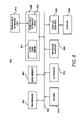
- FIG. 6 shows a schematic diagram of a generated table that includes cells positioned at various locations in the table, according to an embodiment of the invention
- FIG. 7A illustrates a flow diagram of a method similar to the method depicted in FIG. 4A , according to a further embodiment of the invention.
- FIG. 7B illustrates a flow diagram of a method similar to the method depicted in FIG. 7A , according to yet another embodiment of the invention.
- FIG. 8 illustrates a computer system, which may be employed to perform various functions described herein, according to an embodiment of the invention.
- the automatic document layout generation system and method generally operate to automatically generate a layout through the creation and use of convex functions that approximate the height-width relationships of objects containing text, including cells in a table. More particularly, the convex functions are employed to generate clusters of linear constraints that approximate the height-width relationships of the objects containing text. Solutions for these linear constraints may thus be determined through known constraint-satisfaction algorithms. In one regard, therefore, the linear constraints may be employed to automatically determine and generate the layout such that the object containing text is constrained to have suitable dimensions and be positioned in suitable locations as determined by these and other linear constraints.
- the layout 100 includes objects 102 a - 102 n arranged with respect to each other on a document 104 .
- the objects 102 a - 102 n may have been positioned with respect to each other and the document 104 through implementation of various systems and methods described in greater detail herein.
- the “. . . ” depicted in FIG. 1 generally indicate that any reasonably suitable number of objects may be included in the layout 100 .
- the depiction of the objects 102 a - 102 n in FIG. 1 is for purposes of illustration and is not meant to limit the document layout generation systems and methods described herein.
- the objects 102 a - 102 n may comprise text, drawings, photographs, graphic designs, or other images.
- the objects 102 a - 102 n may comprise rectangular or non-rectangular shapes.
- the objects 102 a - 102 n may represent the actual rectangular object or a rectangular bounding box of a rectangular or non-rectangular object 102 a - 102 n.
- the objects 102 a - 102 n may represent rectangular bounding boxes for objects containing text that have non-rectangular shapes.
- one or more of the objects 102 a - 102 n may comprise non-rectangular shapes, such as shown with respect to the object 102 b.
- the objects 102 a - 102 n as used throughout the present disclosure, may be defined as any of the above-identified elements.
- the dimensions of the objects 102 a - 102 n may be expressed as a vector X(i), where “i” represents an object 102 a - 102 n.
- the positions of the objects 102 a - 102 n may be specified as a set of coordinates P(i) directed to, for instance, the top left corners 110 of the objects 102 a - 102 n.
- the coordinates P(i) may be defined according to a Cartesian coordinate system.
- the coordinates P(i) may represent x and y coordinates, with an origin of the x-y coordinate system being located at, for instance, any of the corners of the document 104 , the center of the document 104 , or another arbitrarily selected position in the document 104 .
- each of the objects 102 a - 102 n may be considered as having a reference location 110 .
- the positions and attributes of the objects 102 a - 102 n may be defined as having a position P(i) and a height (h) and width (w) represented by a vector X(i) with respect to the reference location 110 .
- This convention for identifying the positions and dimensions of the objects 102 a - 102 n is employed throughout the present disclosure for purposes of simplicity. It should, however, be understood that various other manners may be employed to identify the positions and sizes of the objects 102 a - 102 n without departing from a scope of the document layout generation systems and methods described herein.
- the layout 100 may be generated in a number of different manners. For instance, if some of the content in an existing document is to be changed to generate the new layout 100 , the new layout 100 may be generated through various layout adjustment techniques.
- An example of a suitable layout adjustment technique is described in co-pending and commonly assigned U.S. patent application Ser. No. 11/107,175, filed on Apr. 15, 2005, and entitled “Automatic Layout Adjustment for Documents Containing Text”, the disclosure of which is hereby incorporated by reference in its entirety.
- a single linear function may be employed to approximate the width-height function around the original layout if only minor changes from the original layout is expected.
- the layout 100 may also be generated from artificially created layout templates.
- the layout templates may specify the topology or slicing structure of the objects 102 a - 102 n, which typically dictate the relative positions of objects 102 a - 102 n on the document 104 .
- the new layout 100 may be generated using conventional linear constraint solving techniques, such as the Simplex algorithm, if the dimensions of the objects 102 a - 102 n are fixed or allowed to change linearly.
- Equation (1) illustrates that a non-linear relationship exists between the width (w) and the height (h) of the object 102 n.
- the exact relationship between the width (w) and the height (h) of the object 102 n is relatively more complex because the height (h) is not a continuous function of the width (w), but instead follows a stepwise pattern.
- FIG. 2 there is shown a graph 200 depicting the stepwise relationship between the height (h) and width (w) of an object 102 n containing text.
- the height-width relationship of the object 102 may comprise a non-continuous stepwise pattern. It should be understood that the graph 200 is merely an example of a possible height-width relationship and is therefore not intended to limit the systems and methods disclosed herein.
- the new layout 100 may be generated through relatively simple and efficient, automated manners, while generally compensating for the non-linear relationships between the widths (w) and the heights (h) of objects 102 a - 102 n containing text. More particularly, for instance, the substantially optimal width-height balance for the objects 102 a - 102 n may be determined through use of multiple linear functions. In one respect, the multiple linear functions may be introduced to solve for the original non-linear width-height relationships of the objects 102 a - 102 n.
- FIG. 3 there is shown a block diagram 300 of a layout generation system 302 suitable for implementing, either fully or partially, various document and table layout generation techniques described herein. It should be understood that the following description of the block diagram 300 is but one manner of a variety of different manners in which such a layout generation system 302 may be configured or operated. In addition, it should be understood that the layout generation system 302 may include additional components and that some of the components described may be removed and/or modified without departing from a scope of the layout generation system 302 . Although the layout generation system 302 is depicted as comprising a computing device, various functions of the layout generation system 302 may be performed by various software and/or hardware contained in a computing device. However, the following description of the layout generation system 302 is set forth with the layout generation system 302 comprising a computing device for purposes of simplicity.
- the layout generation system 302 may comprise a general computing environment and includes a controller 304 configured to control various operations of the layout generation system 302 .
- the controller 304 may comprise a microprocessor, a micro-controller, an application specific integrated circuit (ASIC), and the like.
- Data may be transmitted to various components of the layout generation system 302 over a system bus 306 that operates to couple the various components of the layout generation system 302 .
- the system bus 306 represents any of several types of bus structures, including, for instance, a memory bus, a memory controller, a peripheral bus, an accelerated graphics port, a processor bus using any of a variety of bus architectures, and the like.
- One or more input devices 308 may be employed to input information into the layout generation system 302 .
- the input devices 308 may comprise, for instance, a keyboard, a mouse, an image scanner, a disk drive, removable media, flash drives, and the like.
- the input devices 308 may be used, for instance, to input content to be included in the new layout 100 or the table layout 600 ( FIG. 6 ) and the layout constraints to the layout generation system 302 .
- the input devices 308 are connected to the controller 304 through an interface 310 that is coupled to the system bus 306 .
- the input devices 308 may, however, be coupled by other conventional interface and bus structures, such as, parallel ports, USB ports, etc.
- the controller 304 may be connected to a memory 312 through the system bus 306 .
- the memory 312 may be configured to provide storage of software, algorithms, and the like, that provide the functionality of the layout generation system 302 .
- the memory 312 may store an operating system 314 , application programs 316 , program data 318 , and the like.
- the memory 312 may be implemented as a combination of volatile and non-volatile memory, such as DRAM, EEPROM, MRAM, flash memory, and the like.
- the memory 312 may comprise a device configured to read from and write to a removable media, such as, a floppy disk, a CD-ROM, a DVD-ROM, or other optical or magnetic media.
- the memory 312 may also store modules programmed to perform various layout generation functions. More particularly, the memory 312 may store a content and constraint module 320 , a rendering module 322 , a modeling module 324 , a solution module 326 , a correction module 328 , and a layout generation module 330 . Generally speaking, the controller 304 may implement the modules 320 - 330 to generate the layout 100 of a document 104 or the table layout 600 .
- the controller 304 may implement the content and constraint module 320 to store information regarding various content to be included in the layout 100 , 600 , and the layout constraints to be applied during a layout generation process.
- the content and constraint module 320 may store various aesthetic rules or constraints as constraints in the form of equalities or inequalities, to be applied in the layout 100 , 600 .
- the content and constraint module 320 may encode the aesthetic rules as constraints in the form of equalities or inequalities.
- the controller 304 may also implement content and constraint module 320 to describe the table layout 600 in a table description language.
- the controller 304 may implement the content and constraint module 320 to convert the table description into a set of linear constraints. A more detailed description of these operations is provided herein below with respect to FIG. 7A .
- the controller 304 may implement the rendering module 322 to render the heights of the objects 102 a - 102 n or the cells 602 a - 602 n ( FIG. 6 ) containing text at different widths to determine the actual height-width relationships of the objects 102 a - 102 n or the cells 602 a - 602 n.
- the controller 304 may implement the modeling module 324 to build convex function models of the objects 102 a - 102 n or the cells 602 a - 602 n at the variously rendered heights and widths.
- the modeling module 324 may be implemented to locate sampling points along the convex function models and to calculate linear constraints associated with the convex function models.
- the modeling module 324 may further be implemented to append the calculated linear constraints to existing constraints.
- the controller 304 may implement the solution module 326 to solve the existing constraints and the calculated linear constraints using constraint-satisfaction algorithms.
- the constraint-satisfaction algorithms may be employed to calculate values for the estimated dimensions X′(i) of the objects 102 a - 102 n or the cells 602 a - 502 n and their positions P(i).
- the constraint satisfaction algorithms may comprise, for instance, the Simplex algorithm.
- the controller 304 may implement the correction module 328 to substantially ensure that the values of the estimated dimensions X′(i) for the objects 102 a - 102 n or cells 602 a - 602 n containing text accurately reflect the relationships between the heights and widths of the objects 102 a - 102 n or the cells 602 a - 602 n containing text. More particularly, for instance, the controller 304 may implement the correction module 328 to map the estimated heights and widths of the objects 102 a - 102 n or the cells 602 a - 602 n back to the actual dimensions X(i) to determine whether there are errors in the estimated dimensions X′(i).
- the actual dimensions X(i) may comprise the dimensions of the objects 102 a - 102 n or the cells 602 a - 602 n rendered through implementation of the rendering module 322 . If errors are found, the controller 304 may implement the correction module 328 to replace the erroneous values with correct values.
- the controller 304 may implement the correction module 328 to perform a line breaking redo operation on the objects 120 a - 102 n or cells 602 a - 602 n to ensure that the text may successfully be contained within the estimated dimensions X′(i) of the objects 120 a - 102 n or cells 602 a - 602 n. More particularly, the controller 304 may implement the correction module 328 to redo the line breaks, and in certain instances, the spacing between characters/words, with the constraint that the stack of lines produced must end up having the estimated height. If it is determined that the stack of lines produced does not end up having the estimated height, the controller 304 may implement the correction module 328 to correct the values of the estimated dimensions X′(i) as described herein below.
- the controller 304 may implement the layout generation module 330 to generate the layout 100 , 600 having the attributes and layout determined through implementation of the modules 320 - 328 .
- the controller 304 may also implement the layout generation module 330 to convert the layout 100 , 600 into a conventional format such that the generated layout 100 , 600 may be output from the layout generation system 302 .
- the generated layout 100 , 600 or data pertaining to the generated layout 100 , 600 may be transmitted outside of the layout generation system 302 through one or more adapters 332 .
- the generated layout 100 , 600 data may be transmitted to a network 334 , such as, an internal network, an external network (the Internet), etc.
- the generated layout 100 , 600 data may be outputted to one or more output devices 336 , such as, displays, printers, facsimile machines, etc.
- controller 304 performs various document layout generation functions are described in greater detail herein below with respect to FIGS. 4A-4C , 7 A, and 7 B.
- FIG. 4A there is shown a flow diagram of a method 400 for automatically generating a document layout 100 , 600 .
- the following description of the method 400 is but one manner of a variety of different manners in which the layout 100 , 600 may be generated including the objects 102 a - 102 n or cells 602 a - 602 n.
- the method 400 represents a generalized illustration and that other steps may be added or existing steps may be removed or modified without departing from a scope of the method 400 .
- the description of the method 400 is made with reference to the block diagram 300 illustrated in FIG. 3 , and thus makes reference to the elements cited therein. It should, however, be understood that the method 400 shown in FIG. 4A is not limited to being implemented by the elements shown in FIG. 3 and may be implemented by more, less, or different elements as those shown in FIG. 3 .
- an approximate convex function model for the object 102 a - 102 n or cell 602 a - 602 n containing text is built at step 402 .
- linear constraints associated with the convex function model are calculated.
- the linear constraints are solved using a constraint satisfaction algorithm.
- the document layout is automatically generated based substantially upon the solutions to the linear constraints for the object at step 408 .
- FIGS. 4B , 4 C, 7 A, and 7 B also describe additional steps that may be performed in conjunction with or in place of the steps outlines in the method 400 .
- FIG. 4B there is shown a flow diagram of a method 450 for automatically generating a document layout, according to an example. It is to be understood that the following description of the method 450 is but one manner of a variety of different manners in which the layout may be generated. It should also be apparent to those of ordinary skill in the art that the method 450 represents a generalized illustration and that other steps may be added or existing steps may be removed or modified without departing from a scope of the method 450 . The description of the method 450 is made with reference to the block diagram 300 illustrated in FIG. 3 , and thus makes reference to the elements cited therein. It should, however, be understood that the method 450 shown in FIG. 4B is not limited to being implemented by the elements shown in FIG. 3 and may be implemented by more, less, or different elements as those shown in FIG. 3 .
- the method 450 may be implemented as an automated algorithm for generating the layout 100 of objects 102 a - 102 n according to various criteria as described below.
- generation of the layout 100 includes a determination of the positions P(i) and attributes X(i) of the objects 102 a - 102 n in a document 104 based upon various constraints.
- Generation of the layout 100 also includes placing the objects 102 a - 102 n on the document 104 at their determined positions P(i) and with their determined attributes X(i).
- the layout generation system 302 may receive content and constraints to be used in generating a document 104 having the new layout 100 , at step 452 .
- the content may include content in the form of objects 102 a - 102 n to be included in the document 104 .
- the constraints may be in the form of a template and may include limitations to be applied with respect to one or both of the positions and attributes of the objects 102 a - 102 n. In other words, the constraints may comprise various restrictions in the manners in which the objects 102 a - 102 n are positioned and sized in the new layout 100 .
- the constraints may generally be imposed in order to retain certain aesthetic requirements in the new layout 100 .
- the constraints may comprise, for instance, alignment constraints, aspect ratio constraints, dimension range constraints, separation constraints, order constraints, etc.
- the constraints may require that the object 102 a be above the object 102 b, that the object 102 c must be positioned at a particular location on the document 104 with set attributes, that the object 102 a have a certain set of attributes, etc.
- constraints may also be stored in the form of linear constraints. More particularly, for instance, the layout generation system 302 may receive the constraints in the form of linear constraints having equalities or inequalities. Alternatively, the layout generation system 302 may receive the constraints in the form of aesthetic rules which the layout generation system 302 may encode into constraints in the form of linear constraints having equalities or inequalities.
- less than all of the objects 102 a - 102 n may contain text.
- constraints may be imposed on some of the objects 102 a - 102 n containing text such that some of the objects 102 a - 102 n are restricted to be positioned at a set location or that they have set sizes. As such, some of the objects 102 a - 102 n containing text may be prohibited from being changed in the new layout 100 .
- the objects 102 a - 102 n are rendered at several different widths (w 1 , w 2 , . . . wn) to determine their corresponding heights (h 1 , h 2 , . . . hn).
- widths w 1 , w 2 , . . . wn
- heights h 1 , h 2 , . . . hn
- the width-height relationships may be determined through a method that actually replaces the text content in the objects 102 a - 102 n into various text containers having different widths to determine this width-height relationship.
- An example of a result of this estimation method is shown in Table 1 below, which illustrates discrete pairs of widths and heights.
- the relationships between the various heights and widths shown in Table 1 are considered to be “error-free” representations because the relationships are determined through actual text placement into differently sized text blocks.
- a convex function model may be built based upon the data points (w 1 , h 1 ), (w 2 , h 2 ), . . . (wn, hn) determined at step 454 .
- the convex function model may be built out of a number of rendering results with different (w, h) combinations as shown, for instance, in FIG. 5A .
- FIG. 5A more particularly, shows a graph 500 of a convex function curve 502 built from line segments 504 corresponding to data points (w 1 , h 1 ), (w 2 , h 2 ), . . . (wn, hn).
- the line segments 504 may be formed through a connection between adjacent data points.
- the constants k and b may be calculated through use of any reasonably suitable regression method.
- the constants k and b may be used to solve for various heights in Equation (2) to therefore build the convex function curve 502 .
- convex functions cover all functions whose first-order derivative is always increasing.
- a number of sampling points may be located across the maximal range of widths (w).
- the sampling range of widths for an object 102 a may be between 50 and 500 points and 20 sampling points may be located.
- the number of sampling points may be selected as a trade-off between precision and speed. For instance, a relatively larger number of sampling points may be selected to increase the accuracy, while decreasing the speed at which a layout may be generated.
- the sampling points may be selected such that the intervals between the heights of the sampling points are constant, to thereby ensure that a generally representative range of data points are considered in the layout generation.
- linear constraints associated with the convex function models built at step 456 may be calculated, which define constraints on the height-width relationships of the objects 102 a - 102 n.
- the linear constraints may be calculated for each of the objects 102 a - 102 n containing text whose dimensions X(i) are allowed to change.
- the linear constraints for each of the objects 102 a - 102 n containing text may be based upon the sampling points (i) located from the convex function curve 502 at step 458 .
- Equation (3) may be employed to calculate the linear constraints. More particularly, Equation (3) may be employed to calculate clusters of linear constraints based upon the convex function curves 502 , as determined at step 456 . In addition, the number of linear constraints calculated at step 460 may correspond to the number of sampling points located at step 458 .
- FIG. 5B illustrates a graph 550 , in which, the linear constraints are graphically illustrated in the form of lines 552 a - 552 n, each of which corresponds to a linear constraint.
- the lines 552 a - 552 n form a cluster of linear constraints.
- the cluster of linear constraints may describe the convex relationship between the height and the width of the object 102 a.
- the cluster of linear constraints may be employed to determine the heights that correspond to various widths of the object 102 a with a relatively high degree of precision.
- the linear constraints calculated at step 460 may be appended to existing constraints.
- the existing constraints may include, for instance, various restrictions on either or both the positions P(i) and dimensions X(i) of the objects 102 a - 102 n, as described in greater detail herein above.
- some of the constraints may include that the object 102 a is located to the left of the object 102 b, that the object 102 c have the same width and the object 102 a and is located below the object 102 a, that the object 102 d have a smaller height than the object 102 c, and that the objects 102 a - 102 n containing text may have any width and height values so long as the resulting layout complies with the conditions above.
- the existing constraints may be in the form of linear constraints as described above.
- solutions to the existing constraints and the linear constraints calculated at step 460 may be determined at step 464 .
- the linear constraints may be solved to generally ensure that the constraints are satisfied.
- values for the estimated dimensions X′(i) of the objects (i) containing text and the positions P(i) of the objects (i) may be calculated using constraint-satisfaction algorithms, such as the Simplex algorithm.
- the estimated dimensions X′(i) calculated at step 464 may be mapped back to the actual dimensions X(i) to determine whether there are errors in the estimated dimensions X′(i).
- the actual dimensions X(i) may comprise the dimensions of the objects 102 a - 102 n rendered at step 454 .
- it may be determined as to whether the values for the estimated heights of the objects 102 a - 102 n solved for at step 464 accurately correspond to the estimated widths of the objects 102 a - 102 n.
- Step 468 may be performed, for instance, because the convex function models for the objects 102 a - 102 n calculated at step 460 are approximations.
- the comparison may be based upon the actual height that correlates to a given width for each of the objects 102 a - 102 n, which may be determined through actual content placement of the objects 102 a - 102 n with the widths fixed at the values calculated at step 454 .
- the actual correlation between the height and the width of an object 102 n may be determined through use of any reasonably suitable known line-breaking algorithm.
- a correction may be made to the object 102 n, such that the height of the object 102 n may be fixed to the actual height, as indicated at step 470 .
- a solution to the linear constraints outputted an indication that the width of the object 102 c (w( 102 c )) is equal to 172.8 and that the height of the object 102 c (h( 102 c )) is equal to 254.9.
- the relationship between the width of the object 102 c (w( 102 c )) and the height of the object 102 c (h( 102 c )) is based upon the multi-linear model approximated at step 460 , and thus may be inaccurate. More particularly, for instance, the relationship may be inaccurate because the text may have been broken into a number of lines whose width is the solution width and the height of all lines may be more than or less than the solution height.
- the determination of the height of the object 102 c (h( 102 c )) may also be performed through any reasonably suitable line-breaking algorithm, for instance.
- the height of the object 102 c (h( 102 c )) in this example may be equal to 202.5, which differs from the height value calculated for the object 102 c at step 454 . As such, the less accurate value of 254.9 is replaced with the more accurate value of 202.5 for the ⁇ height of the object 102 c ( ⁇ h( 102 c )) for subsequent operations in the method 450 .
- the dimensions (X(i)) of the objects 102 a - 102 n may be fixed and the linear constraints may be solved again to determine the corrected positions (P(i)) of the objects 102 a - 102 n, at step 472 . More particularly, the positions (P(i)) of the objects 102 a - 102 n may be optimized using constraint-satisfaction algorithms, for instance, as described with respect to step 464 .
- the constraints employed at step 472 for the dimensions (X(i)) of the objects 102 a - 102 n may include the widths for the objects 102 a - 102 n determined at step 464 and the corresponding heights for the objects 102 a - 102 n determined at step 470 .
- the solutions to the constraints calculated by a constraint-solving algorithm to solve the linear constraints for the positions (P(i)) of the objects 102 a - 102 n at step 472 may differ from the solutions calculated at step 464 because the constraints identifying the constraints have changed from those employed at step 464 .
- the new layout 100 may be rendered such that the objects 102 a - 102 n have the dimensions X′(i) and are positioned according to the positions P(i) determined at step 464 .
- the new layout 100 may be rendered such that the objects 102 a - 102 n have the dimensions (X(i)) determined at step 470 and the objects 102 1 - 102 n are positioned according to the positions (P(i)) of the objects 102 a - 102 n determined at step 472 , if a correction is made at step 470 .
- step 474 may also include outputting of the new layout 100 in any reasonably suitable format, such as, a portable document file (PDF).
- PDF portable document file
- FIG. 4C there is shown a flow diagram of a method 480 for automatically generating a document layout, according to another example.
- the method 480 contains many of the same or similar steps as contained in the method 450 . As such, the same or similar steps will not be described in detail with respect to the method 480 . Instead, the differences between the method 480 and the method 450 will be described below.
- a line breaking redo operation is performed at step 482 .
- a description of the line breaking redo operation is presented by way of the following example.
- An object 102 n contains text and is subject to a text constraint.
- a solution of the approximate constraints produces a solution with the object positioned at P( 102 n ) and having the dimensions w( 102 n ) and h( 102 n ) estimated at step 464 .
- the line breaks for the object 102 n are recomputed using the estimated width w( 102 n ) and choosing the breaks to produce the best line-breaking possible subject to the extra constraint that the stack of lines produced must end up having the estimated height h( 102 n ).
- the line breaks of the text, and in certain instances, the spacing between words/characters, contained in the object 102 n may be modified such that the object 102 n has the estimated height h( 102 n ).
- step 484 it may be determined as to whether the line breaking redo operation was successful.
- the line breaking redo operation may, in certain instances, be unable to fit the text into the estimated height h( 102 n ), and may thus be unsuccessful.
- some of the steps contained in the method 450 may be invoked beginning at step 466 ( FIG. 4B ).
- steps 468 - 474 may also be performed following step 466 as described hereinabove.
- the new layout 100 may be rendered, at step 486 , such that the objects 102 1 - 102 n have the dimensions X′(i) and are positioned according to the positions P(i) determined at step 464 .
- FIGS. 4A-4C may be implemented in other publishing operations. For instance, these principles may be implemented in formatting a table, where the optimal layout of table cells, given the grid structure of the table and the content to be included in the table, are to be determined.
- the optimal table layout may be defined as the layout that leads to the minimal table height, while satisfying other aesthetic criteria, such as balance.
- FIG. 6 An example of a table layout 600 containing a plurality of cells 602 a - 602 n upon which the various principles described above may be employed is depicted in FIG. 6 .
- the cells 602 a - 602 n generally comprise non-uniform heights and widths and are thus configured to contain one or both of text and images of varying sizes.
- the depiction of the cells 602 a - 602 n in FIG. 6 is for purposes of illustration and is not meant to limit the document layout generation systems and method described herein.
- many of the principles described above with respect to the document layout 100 and the objects 102 a - 102 n are applicable to the table layout 600 and the cells 602 a - 602 n. As such, much of the description above with respect to the objects 102 a - 102 n and the document layout 100 may be applied to the cells 602 a - 602 n and the table layout 600 as described below.
- each of the cells 602 a - 602 n may be expressed as a vector X(i), where “i” represents a cell 602 1 - 602 n.
- the position of each of the cells 602 a - 602 n may be specified as a set of coordinates P(i) defined according to a Cartesian coordinate system. As such, the coordinates P(i) may represent x and y coordinates, as shown in FIG. 6 .
- This convention for identifying the positions and dimensions of the cells 602 a - 602 n is employed throughout the present disclosure for purposes of simplicity. It should, however, be understood that various other manners may be employed to identify the positions and sizes of the cells 602 a - 602 n without departing from a scope of the document layout generation systems and methods described herein.
- FIG. 7A there is shown a there is shown a flow diagram of a method 700 for automatically generating a table layout. It is to be understood that the following description of the method 700 is but one manner of a variety of different manners in which the table layout may be generated. It should also be apparent to those of ordinary skill in the art that the method 700 represents a generalized illustration and that other steps may be added or existing steps may be removed or modified without departing from a scope of the method 700 . The description of the method 700 is made with reference to the block diagram 300 illustrated in FIG. 3 , and thus makes reference to the elements cited therein. It should, however, be understood that the method 700 is not limited to being implemented by the elements shown in FIG. 3 and may be implemented by more, less, or different elements as those shown in FIG. 3 .
- the method 700 may be implemented as an automated algorithm for generating a table layout, such as the table layout 600 of cells 602 a - 602 n depicted in FIG. 6 , according to various criteria as described below.
- generation of the table layout 600 includes a determination of the positions P(i) and attributes X(i) of the cells 602 a - 602 n based upon various constraints and other criteria.
- generation of the table layout 600 also includes placing the cells 602 a - 602 n in the table layout 600 at their determined positions and with their determined attributes.
- the layout generation system 302 may receive content and layout constraints to be used in generating a table layout 600 , at step 702 .
- the content may include content in the form of text to be included in the various cells 602 a - 602 n.
- the constraints may be in the form of a template and may include limitations to be applied with respect to one or both of the positions P(i) and attributes X(i) of the cells 602 a - 602 n. In other words, the constraints may comprise various restrictions in the manners in which the cells 602 a - 602 n are positioned and sized in the table layout 600 .
- the constraints may generally be imposed in order to retain certain aesthetic requirements in the table layout 600 as well as to ensure that the cells 602 a - 602 n are arranged in a logical manner.
- the constraints may comprise, for instance, alignment constraints, aspect ratio constraints, dimension range constraints, separation constraints, order constraints, etc.
- the constraints may require that the cell 602 a be above the cell 602 b, that the cell 602 f have the same height as the combined heights of cells 602 b and 602 c, etc.
- the table layout 600 may be described in any reasonably suitable table description language, such as, for instance, Extensible Markup Language (XML), at step 704 .
- XML Extensible Markup Language
- adaptors using programs such as Extensible Stylesheet Language Transformations (XSLT) and DOM/SAX may be implemented to convert other description language formats into a desired table description language.
- XSLT Extensible Stylesheet Language Transformations
- DOM/SAX may be implemented to convert other description language formats into a desired table description language.
- An example of an XSLT is Java API for XML Processing (JAXP) to XSL-FO.
- the table description may be converted into a set of linear constraints that define a number of constraints. Any reasonably suitable converter program may be employed to convert the table description into the set of linear constraints.
- Additional constraints in the form of linear constraints may also be added, for instance, to generally enhance the aesthetics of the table layout 600 .
- additional constraints may be added to ensure that the table layout 600 comprise a minimal height.
- the additional constraints may also be in the form of linear constraints.
- the layout generation system 302 may receive the constraints in the form of linear constraints having equalities or inequalities.
- the layout generation system 302 may receive the constraints in the form of aesthetic rules which the layout generation system 302 may encode into constraints in the form of linear constraints having equalities or inequalities.
- table description language may also be used to generate the layout description, which may be used to render the table layout 600 after the constraints are solved.
- the cells 602 a - 602 n are rendered at several different widths (w 1 , w 2 , . . . wn) to determine their corresponding heights (h 1 , h 2 , . . . hn).
- w 1 , w 2 , . . . wn widths
- h 1 , h 2 , . . . hn heights
- the width-height relationships may be determined through a method that actually replaces the text content in the cells 602 a - 602 n into various text containers having different widths to determine this width-height relationship.
- An example of a result of this estimation method is shown in Table 1 above, which illustrates discrete pairs of widths and heights.
- a convex function model may be built based upon the data points (w 1 , h 1 ), (w 2 , h 2 ), . . . (wn, hn) determined at step 708 .
- the convex function model may be built out of a number of rendering results with different (w, h) combinations as described in greater detail hereinabove with respect to FIG. 4B .
- a number of sampling points may be located across the maximal range of widths (w).
- the sampling range of widths for a cell 602 a may be between 50 and 500 points and 20 sampling points may be located.
- the number of sampling points may be selected as a trade-off between precision and speed. For instance, a relatively larger number of sampling points may be selected to increase the accuracy, while decreasing the speed at which a layout may be generated.
- the sampling points may be selected such that the intervals between the heights of the sampling points are constant, to thereby ensure that a generally representative range of data points are considered in the layout generation.
- linear constraints associated with the convex function models for the cells 602 a - 602 n built at step 710 may be calculated.
- the linear constraints may be calculated for each of the cells 602 a - 602 n containing text whose dimensions X(i) are allowed to change.
- the linear constraints for each of the cells 602 a - 602 n containing text may be based upon the sampling points located from the convex function curve 502 at step 712 , and may be determined through Equation (3) cited above.
- Equation (3) may be employed to calculate the linear constraints. More particularly, Equation (3) may be employed to calculate clusters of linear constraints based upon the convex function curves 502 , as determined at step 710 . In addition, the number of linear constraints calculated at step 714 may correspond to the number of sampling points located at step 712 .
- An example of the linear constraints for a cell 602 a containing text corresponding to a convex function curve 502 is depicted in FIG. 5B and is described in greater detail hereinabove.
- the linear constraints calculated at step 714 may be appended to the existing constraints, which may also be in the form of linear constraints.
- the existing constraints may include, for instance, various restrictions on either or both the positions P(i) and dimensions X(i) of the cells 602 a - 602 n, as described in greater detail herein above.
- Solutions to the existing constraints and the linear constraints calculated at step 716 may be determined at step 718 . More particularly, at step 718 , the linear constraints may be solved to generally ensure that the existing constraints and the linear constraints calculated at step 716 are satisfied. In solving the linear constraints, values for the estimated dimensions X′(i) of the objects (i) containing text and the positions P(i) of the objects (i) may be calculated using constraint-satisfaction algorithms, such as the Simplex algorithm, as also described hereinabove with respect to FIG. 4B .
- the estimated dimensions X′(i) calculated at step 718 may be mapped back to the actual dimensions X(i) to determine whether there are errors in the estimated dimensions X′(i).
- the actual dimensions X(i) may comprise the dimensions of the cells 602 a - 602 n rendered at step 708 .
- it may be determined as to whether the values for the estimated heights of the cells 602 a - 602 n solved for at step 718 accurately correspond to the estimated widths of the cells 602 a - 602 n. Step 722 may be performed, for instance, because the convex function models for the cells 602 a - 602 n calculated at step 714 are approximations.
- the comparison may be based upon the actual height that correlates to a given width for each of the cells 602 a - 602 n, which may be determined through actual content placement of the cells 602 a - 602 n with the widths fixed at the values calculated at step 708 .
- the actual correlation between the height and the width of a cell 602 n may be determined through use of any reasonably suitable known line-breaking algorithm.
- a correction may be made to the cell 602 n, such that the height of the cell 602 n may be fixed to the actual height, as indicated at step 724 .
- An example of steps 718 - 724 is provided above with respect to steps 466 - 470 and is thus not repeated here.
- the dimensions (X(i)) of the cells 602 a - 602 n may be fixed and the linear constraints may be solved again to determine the corrected positions (P(i)) of the cells 602 a - 602 n, at step 726 . More particularly, the positions (P(i)) of the cells 602 a - 602 n may be optimized using constraint-satisfaction algorithms, for instance, as described with respect to step 718 .
- constraints employed at step 726 for the dimensions (X(i)) of the cells 602 a - 602 n may include the widths for the cells 602 a - 602 n determined at step 718 and the corresponding heights for the cells 602 a - 602 n determined at step 724 .
- the solutions to the constraints calculated by a constraint-solving algorithm to optimize a layout quality function for the positions (P(i)) of the cells 602 a - 602 n at step 726 may differ from the solutions calculated at step 718 because the constraints identifying the constraints have changed from those employed at step 718 .
- the table layout 600 may be rendered such that the cells 602 a - 602 n have the dimensions X′(i) and are positioned according to the positions P(i) determined at step 718 .
- the table layout 600 may be rendered such that the cells 602 a - 602 n have the dimensions (X(i)) determined at step 724 and the cells 602 a - 602 n are positioned according to the positions (P(i)) of the cells 602 a - 602 n determined at step 726 , if a correction is made at step 724 .
- step 728 may also include outputting of the table layout 600 in any reasonably suitable format, such as, a portable document file (PDF).
- PDF portable document file
- FIG. 7B there is shown a flow diagram of a method 750 for automatically generating a table layout, according to another example.
- the method 750 contains many of the same or similar steps as contained in the method 700 shown in FIG. 7A . As such, the same or similar steps will not be described in detail with respect to the method 750 . Instead, the differences between the method 700 and the method 750 will be described below.
- a line breaking redo operation is performed at step 752 .
- a description of the line breaking redo operation is presented by way of the following example.
- a cell 602 n contains text and is subject to a text constraint.
- a solution of the approximate constraints produces a solution with the cell positioned at P( 602 n ) and having the dimensions w( 602 n ) and h( 602 n ) estimated at step 718 .
- the line breaks for the cell 602 n are recomputed using the estimated width w( 602 n ) and choosing the breaks to produce the best line-breaking possible subject to the extra constraint that the stack of lines produced must end up having the estimated height h( 602 n ).
- the line breaks of the text, and in certain instances, the spacing between words/characters, contained in the cell 602 n may be modified such that the cell 602 n has the estimated height h( 602 n ).
- step 754 it may be determined as to whether the line breaking redo operation was successful.
- the line breaking redo operation may, in certain instances, be unable to fit the text into the estimated height h( 602 n ), and may thus be unsuccessful.
- some of the steps contained in the method 700 may be invoked beginning at step 720 ( FIG. 7A ).
- steps 722 - 728 may also be performed following step 720 as described hereinabove.
- the table layout 600 may be rendered, at step 756 , such that the cells 602 a - 602 n have the dimensions X′(i) and are positioned according to the positions P(i) determined at step 718 .
- Some or all of the operations illustrated in the methods 400 , 450 , 480 , 700 , and 750 may be contained as a utility, program, or a subprogram, in any desired computer accessible medium.
- the methods 400 , 450 , 480 , 700 , and 750 may be embodied by a computer program, which can exist in a variety of forms both active and inactive. For example, they can exist as software program(s) comprised of program instructions in source code, object code, executable code or other formats. Any of the above can be embodied on a computer readable medium, which include storage devices and signals, in compressed or uncompressed form.
- Exemplary computer readable storage devices include conventional computer system RAM, ROM, EPROM, EEPROM, and magnetic or optical disks or tapes.
- Exemplary computer readable signals are signals that a computer system hosting or running the computer program can be configured to access, including signals downloaded through the Internet or other networks. Concrete examples of the foregoing include distribution of the programs on a CD ROM or via Internet download. In a sense, the Internet itself, as an abstract entity, is a computer readable medium. The same is true of computer networks in general. It is therefore to be understood that any electronic device capable of executing the above-described functions may perform those functions enumerated above.
- FIG. 8 illustrates a computer system 800 , which may be employed to perform various functions described herein.
- the computer system 800 may include, for example, the controller 304 .
- the computer system 800 may be used as a platform for executing one or more of the functions described herein above with respect to the various components of the layout generation system 302 .
- the computer system 800 includes one or more controllers, such as a processor 802 .
- the processor 802 may be used to execute some or all of the steps described in the methods 400 , 450 , 480 , 700 , and 750 . Commands and data from the processor 802 are communicated over a communication bus 804 .
- the computer system 800 also includes a main memory 806 , such as a random access memory (RAM), where the program code for, for instance, the controller 304 , may be executed during runtime, and a secondary memory 808 .
- main memory 806 such as a random access memory (RAM)
- the secondary memory 808 includes, for example, one or more hard disk drives 810 and/or a removable storage drive 812 , representing a floppy diskette drive, a magnetic tape drive, a compact disk drive, etc., where a copy of the program code for the layout generation system 302 may be stored.
- the removable storage drive 810 reads from and/or writes to a removable storage unit 814 in a well-known manner.
- User input and output devices may include a keyboard 816 , a mouse 818 , and a display 820 .
- a display adaptor 822 may interface with the communication bus 804 and the display 820 and may receive display data from the processor 802 and convert the display data into display commands for the display 820 .
- the processor 802 may communicate over a network, for instance, the Internet, LAN, etc., through a network adaptor 824 .
- the computer system 800 may include a system board or blade used in a rack in a data center, a conventional “white box” server or computing device, etc. Also, one or more of the components in FIG. 8 may be optional (for instance, user input devices, secondary memory, etc.).
Abstract
Description
w(i)*h(i)=a, where a is a constant. Equation (1)
Equation (1) illustrates that a non-linear relationship exists between the width (w) and the height (h) of the
| TABLE 1 |
| Lookup Table for Height-Width Relationship |
| Width (wn) | 200 | . . . | 340 350 360 370 380 390 | . . . | 500 |
| (points) | |||||
| Height (hn) | 41 | . . . | 24 23 22 22 21 20 | . . . | 16 |
| (lines) | |||||
h(w)=k/w+b, where k and b are constant for a given text content and format. (Equation (2)
F(w,i)=h[i]+(h[i]−h[i−1])*(w−w[i−1])/(w[i]−w[i−1]), where
h>=F(w,i), i=1, . . . , n. Equation (3)
h(102 c)>=67.6−(w(102 c)−1059.5)*0.067
h(102 c)>=101.9−(w(102 c)−543.6)*0.19 Equation (4)
w(102 c)=172.8. Equation (5)
h(102 c)=202.5. Equation (6)
Claims (22)
Priority Applications (1)
| Application Number | Priority Date | Filing Date | Title |
|---|---|---|---|
| US11/126,637 US7434159B1 (en) | 2005-05-11 | 2005-05-11 | Automatically layout of document objects using an approximate convex function model |
Applications Claiming Priority (1)
| Application Number | Priority Date | Filing Date | Title |
|---|---|---|---|
| US11/126,637 US7434159B1 (en) | 2005-05-11 | 2005-05-11 | Automatically layout of document objects using an approximate convex function model |
Publications (1)
| Publication Number | Publication Date |
|---|---|
| US7434159B1 true US7434159B1 (en) | 2008-10-07 |
Family
ID=39797406
Family Applications (1)
| Application Number | Title | Priority Date | Filing Date |
|---|---|---|---|
| US11/126,637 Expired - Fee Related US7434159B1 (en) | 2005-05-11 | 2005-05-11 | Automatically layout of document objects using an approximate convex function model |
Country Status (1)
| Country | Link |
|---|---|
| US (1) | US7434159B1 (en) |
Cited By (21)
| Publication number | Priority date | Publication date | Assignee | Title |
|---|---|---|---|---|
| US20060224953A1 (en) * | 2005-04-01 | 2006-10-05 | Xiaofan Lin | Height-width estimation model for a text block |
| US20070006072A1 (en) * | 2005-06-29 | 2007-01-04 | Xerox Corporation | Constraint-optimization method for document layout using tradeoff generation |
| US20070044014A1 (en) * | 2005-08-19 | 2007-02-22 | Vistaprint Technologies Limited | Automated markup language layout |
| US20070100874A1 (en) * | 2005-10-27 | 2007-05-03 | Helen Balinsky | Grouping of information items on a page |
| US20070208996A1 (en) * | 2006-03-06 | 2007-09-06 | Kathrin Berkner | Automated document layout design |
| US20080037873A1 (en) * | 2003-01-29 | 2008-02-14 | Kathrin Berkner | Reformatting documents using document analysis information |
| US20080235207A1 (en) * | 2007-03-21 | 2008-09-25 | Kathrin Berkner | Coarse-to-fine navigation through paginated documents retrieved by a text search engine |
| US20090204891A1 (en) * | 2005-08-19 | 2009-08-13 | Vistaprint Technologies Limited | Automated product layout |
| US20090254814A1 (en) * | 2008-04-08 | 2009-10-08 | Microsoft Corporation | Per-edge rules and constraints-based layout mechanism |
| US7761789B2 (en) | 2006-01-13 | 2010-07-20 | Ricoh Company, Ltd. | Methods for computing a navigation path |
| US20110206007A1 (en) * | 2005-04-29 | 2011-08-25 | Nortel Networks Limited | Active Set Management Enhancement for Reliable Soft Handoff in 1XEV-DO System |
| US20120036427A1 (en) * | 2005-02-28 | 2012-02-09 | Canon Kabushiki Kaisha | Document processing apparatus, document processing method and computer program |
| US20120204098A1 (en) * | 2009-10-28 | 2012-08-09 | Niranjan Damera Venkata | Methods and Systems for Preparing Mixed-Content Documents |
| US20130185630A1 (en) * | 2012-01-13 | 2013-07-18 | Ildus Ahmadullin | Document aesthetics evaluation |
| US8584042B2 (en) | 2007-03-21 | 2013-11-12 | Ricoh Co., Ltd. | Methods for scanning, printing, and copying multimedia thumbnails |
| US8812969B2 (en) | 2007-03-21 | 2014-08-19 | Ricoh Co., Ltd. | Methods for authoring and interacting with multimedia representations of documents |
| US20140372842A1 (en) * | 2012-03-06 | 2014-12-18 | Ildus Ahmadullin | Hierarchical Probabilistic Document Model Based Document Composition |
| US9152292B2 (en) | 2009-02-05 | 2015-10-06 | Hewlett-Packard Development Company, L.P. | Image collage authoring |
| WO2016057184A1 (en) * | 2014-10-09 | 2016-04-14 | Wrap Media, LLC | System and method for authoring, distributing, viewing and saving wrap packages |
| US10394935B2 (en) | 2014-02-27 | 2019-08-27 | International Business Machines Corporation | Dynamically displaying online documents based on document object attributes |
| US10635483B2 (en) | 2017-09-29 | 2020-04-28 | Red Hat, Inc. | Automatic synopsis generation for command-line interfaces |
Citations (13)
| Publication number | Priority date | Publication date | Assignee | Title |
|---|---|---|---|---|
| US6088708A (en) | 1997-01-31 | 2000-07-11 | Microsoft Corporation | System and method for creating an online table from a layout of objects |
| US6144974A (en) | 1996-12-13 | 2000-11-07 | Adobe Systems Incorporated | Automated layout of content in a page framework |
| US20040019850A1 (en) | 2002-07-23 | 2004-01-29 | Xerox Corporation | Constraint-optimization system and method for document component layout generation |
| US20040019852A1 (en) | 2002-07-23 | 2004-01-29 | Xerox Corporation | System and method for constraint-based document generation |
| US20040019851A1 (en) | 2002-07-23 | 2004-01-29 | Xerox Corporation | Constraint-optimization system and method for document component layout generation |
| US6697999B1 (en) | 1999-10-20 | 2004-02-24 | Sun Microsystems, Inc. | Computer-based automatic document formatting method |
| US20050094207A1 (en) * | 2003-10-15 | 2005-05-05 | Canon Kabushiki Kaisha | User interface for creation and editing of variable data documents |
| US6907431B2 (en) * | 2002-05-03 | 2005-06-14 | Hewlett-Packard Development Company, L.P. | Method for determining a logical structure of a document |
| US20060179405A1 (en) * | 2005-02-10 | 2006-08-10 | Hui Chao | Constraining layout variations for accommodating variable content in electronic documents |
| US20060224953A1 (en) * | 2005-04-01 | 2006-10-05 | Xiaofan Lin | Height-width estimation model for a text block |
| US20060224952A1 (en) * | 2005-03-30 | 2006-10-05 | Xiaofan Lin | Adaptive layout templates for generating electronic documents with variable content |
| US7151547B2 (en) * | 2004-11-23 | 2006-12-19 | Hewlett-Packard Development Company, L.P. | Non-rectangular image cropping methods and systems |
| US20080072183A1 (en) * | 2004-09-30 | 2008-03-20 | Mar Hershenson | Novel optimization for circuit design |
-
2005
- 2005-05-11 US US11/126,637 patent/US7434159B1/en not_active Expired - Fee Related
Patent Citations (14)
| Publication number | Priority date | Publication date | Assignee | Title |
|---|---|---|---|---|
| US6144974A (en) | 1996-12-13 | 2000-11-07 | Adobe Systems Incorporated | Automated layout of content in a page framework |
| US6088708A (en) | 1997-01-31 | 2000-07-11 | Microsoft Corporation | System and method for creating an online table from a layout of objects |
| US6697999B1 (en) | 1999-10-20 | 2004-02-24 | Sun Microsystems, Inc. | Computer-based automatic document formatting method |
| US6907431B2 (en) * | 2002-05-03 | 2005-06-14 | Hewlett-Packard Development Company, L.P. | Method for determining a logical structure of a document |
| US20040205472A1 (en) | 2002-07-23 | 2004-10-14 | Xerox Corporation | System and method for constraint-based document generation |
| US20040019851A1 (en) | 2002-07-23 | 2004-01-29 | Xerox Corporation | Constraint-optimization system and method for document component layout generation |
| US20040019852A1 (en) | 2002-07-23 | 2004-01-29 | Xerox Corporation | System and method for constraint-based document generation |
| US20040019850A1 (en) | 2002-07-23 | 2004-01-29 | Xerox Corporation | Constraint-optimization system and method for document component layout generation |
| US20050094207A1 (en) * | 2003-10-15 | 2005-05-05 | Canon Kabushiki Kaisha | User interface for creation and editing of variable data documents |
| US20080072183A1 (en) * | 2004-09-30 | 2008-03-20 | Mar Hershenson | Novel optimization for circuit design |
| US7151547B2 (en) * | 2004-11-23 | 2006-12-19 | Hewlett-Packard Development Company, L.P. | Non-rectangular image cropping methods and systems |
| US20060179405A1 (en) * | 2005-02-10 | 2006-08-10 | Hui Chao | Constraining layout variations for accommodating variable content in electronic documents |
| US20060224952A1 (en) * | 2005-03-30 | 2006-10-05 | Xiaofan Lin | Adaptive layout templates for generating electronic documents with variable content |
| US20060224953A1 (en) * | 2005-04-01 | 2006-10-05 | Xiaofan Lin | Height-width estimation model for a text block |
Cited By (35)
| Publication number | Priority date | Publication date | Assignee | Title |
|---|---|---|---|---|
| US20080037873A1 (en) * | 2003-01-29 | 2008-02-14 | Kathrin Berkner | Reformatting documents using document analysis information |
| US7792362B2 (en) | 2003-01-29 | 2010-09-07 | Ricoh Co., Ltd. | Reformatting documents using document analysis information |
| US8578269B2 (en) * | 2005-02-28 | 2013-11-05 | Canon Kabushiki Kaisha | Information processing apparatus for performing a layout processing of sub-templates, information processing method and computer-readable medium |
| US20120036427A1 (en) * | 2005-02-28 | 2012-02-09 | Canon Kabushiki Kaisha | Document processing apparatus, document processing method and computer program |
| US20060224953A1 (en) * | 2005-04-01 | 2006-10-05 | Xiaofan Lin | Height-width estimation model for a text block |
| US8699415B2 (en) | 2005-04-29 | 2014-04-15 | Apple Inc. | Active set management enhancement for reliable soft handoff in 1XEV-DO system |
| US20110206007A1 (en) * | 2005-04-29 | 2011-08-25 | Nortel Networks Limited | Active Set Management Enhancement for Reliable Soft Handoff in 1XEV-DO System |
| US20070006072A1 (en) * | 2005-06-29 | 2007-01-04 | Xerox Corporation | Constraint-optimization method for document layout using tradeoff generation |
| US8522140B2 (en) | 2005-08-19 | 2013-08-27 | Vistaprint Technologies Limited | Automated markup language layout |
| US20090204891A1 (en) * | 2005-08-19 | 2009-08-13 | Vistaprint Technologies Limited | Automated product layout |
| US8793570B2 (en) | 2005-08-19 | 2014-07-29 | Vistaprint Schweiz Gmbh | Automated product layout |
| US7676744B2 (en) * | 2005-08-19 | 2010-03-09 | Vistaprint Technologies Limited | Automated markup language layout |
| US20100131839A1 (en) * | 2005-08-19 | 2010-05-27 | Vistaprint Technologies Limited | Automated markup language layout |
| US20070044014A1 (en) * | 2005-08-19 | 2007-02-22 | Vistaprint Technologies Limited | Automated markup language layout |
| US7831907B2 (en) * | 2005-10-27 | 2010-11-09 | Hewlett-Packard Development Company, L.P. | Grouping of information items on a page |
| US20070100874A1 (en) * | 2005-10-27 | 2007-05-03 | Helen Balinsky | Grouping of information items on a page |
| US7761789B2 (en) | 2006-01-13 | 2010-07-20 | Ricoh Company, Ltd. | Methods for computing a navigation path |
| US20070208996A1 (en) * | 2006-03-06 | 2007-09-06 | Kathrin Berkner | Automated document layout design |
| US7788579B2 (en) * | 2006-03-06 | 2010-08-31 | Ricoh Co., Ltd. | Automated document layout design |
| US8812969B2 (en) | 2007-03-21 | 2014-08-19 | Ricoh Co., Ltd. | Methods for authoring and interacting with multimedia representations of documents |
| US20080235207A1 (en) * | 2007-03-21 | 2008-09-25 | Kathrin Berkner | Coarse-to-fine navigation through paginated documents retrieved by a text search engine |
| US8583637B2 (en) | 2007-03-21 | 2013-11-12 | Ricoh Co., Ltd. | Coarse-to-fine navigation through paginated documents retrieved by a text search engine |
| US8584042B2 (en) | 2007-03-21 | 2013-11-12 | Ricoh Co., Ltd. | Methods for scanning, printing, and copying multimedia thumbnails |
| US20090254814A1 (en) * | 2008-04-08 | 2009-10-08 | Microsoft Corporation | Per-edge rules and constraints-based layout mechanism |
| US9152292B2 (en) | 2009-02-05 | 2015-10-06 | Hewlett-Packard Development Company, L.P. | Image collage authoring |
| US20120204098A1 (en) * | 2009-10-28 | 2012-08-09 | Niranjan Damera Venkata | Methods and Systems for Preparing Mixed-Content Documents |
| US8468448B2 (en) * | 2009-10-28 | 2013-06-18 | Hewlett-Packard Development Company, L.P. | Methods and systems for preparing mixed-content documents |
| US20130185630A1 (en) * | 2012-01-13 | 2013-07-18 | Ildus Ahmadullin | Document aesthetics evaluation |
| US8977956B2 (en) * | 2012-01-13 | 2015-03-10 | Hewlett-Packard Development Company, L.P. | Document aesthetics evaluation |
| US20140372842A1 (en) * | 2012-03-06 | 2014-12-18 | Ildus Ahmadullin | Hierarchical Probabilistic Document Model Based Document Composition |
| US10223348B2 (en) * | 2012-03-06 | 2019-03-05 | Hewlett-Packard Development Company, L.P. | Hierarchical probabilistic document model based document composition |
| US10394935B2 (en) | 2014-02-27 | 2019-08-27 | International Business Machines Corporation | Dynamically displaying online documents based on document object attributes |
| US10565290B2 (en) | 2014-02-27 | 2020-02-18 | International Business Machines Corporation | Online displaying a document |
| WO2016057184A1 (en) * | 2014-10-09 | 2016-04-14 | Wrap Media, LLC | System and method for authoring, distributing, viewing and saving wrap packages |
| US10635483B2 (en) | 2017-09-29 | 2020-04-28 | Red Hat, Inc. | Automatic synopsis generation for command-line interfaces |
Similar Documents
| Publication | Publication Date | Title |
|---|---|---|
| US7434159B1 (en) | Automatically layout of document objects using an approximate convex function model | |
| US20060236230A1 (en) | Automatic layout adjustment for documents containing text | |
| US8762832B2 (en) | Constraint and rule-based page layout | |
| US7750924B2 (en) | Method and computer-readable medium for generating graphics having a finite number of dynamically sized and positioned shapes | |
| US7634725B2 (en) | Layout adjustment method, apparatus and program for the same | |
| JP4572669B2 (en) | Layout rule generation system, layout system, layout rule generation method, and layout rule generation program | |
| US8327262B2 (en) | Layout editing apparatus and layout editing method | |
| US20100153834A1 (en) | Business form creating system, network system using the same, and business form creating method | |
| US20070126793A1 (en) | Digital content creation system, digital content creation method, and program product | |
| US20070061715A1 (en) | Methods and systems for providing an editable visual formatting model | |
| US20090254814A1 (en) | Per-edge rules and constraints-based layout mechanism | |
| EP0782103B1 (en) | Automatic graphical pattern placement | |
| US8375298B2 (en) | Method and apparatus for processing layout and storage medium | |
| JP2008293483A (en) | Method for laying out graphical element on page | |
| US20110221764A1 (en) | Laying out and cropping images in pre-defined layouts | |
| CN110096275B (en) | Page processing method and device | |
| US20050091585A1 (en) | Systems and methods for pagination and co-pagination | |
| US20120102385A1 (en) | Determining heights of table cells | |
| JP4992350B2 (en) | Document editing apparatus and program | |
| US10657427B2 (en) | Information processing apparatus, information processing method and storage medium | |
| US8869026B2 (en) | Using a layout engine to display an overflowed textbox | |
| US20100147960A1 (en) | Methods, devices, and systems for printing bar codes | |
| EP3422251A1 (en) | Typesetness score for a table | |
| WO2014209387A1 (en) | Quality distributions for automated document composition | |
| US20060224953A1 (en) | Height-width estimation model for a text block |
Legal Events
| Date | Code | Title | Description |
|---|---|---|---|
| AS | Assignment |
Owner name: HEWLETT-PACKARD DEVELOPMENT COMPANY L.P., TEXAS Free format text: ASSIGNMENT OF ASSIGNORS INTEREST;ASSIGNOR:LIN, XIAOFAN;REEL/FRAME:016557/0304 Effective date: 20050511 |
|
| STCF | Information on status: patent grant |
Free format text: PATENTED CASE |
|
| CC | Certificate of correction | ||
| FPAY | Fee payment |
Year of fee payment: 4 |
|
| FPAY | Fee payment |
Year of fee payment: 8 |
|
| FEPP | Fee payment procedure |
Free format text: MAINTENANCE FEE REMINDER MAILED (ORIGINAL EVENT CODE: REM.); ENTITY STATUS OF PATENT OWNER: LARGE ENTITY |
|
| LAPS | Lapse for failure to pay maintenance fees |
Free format text: PATENT EXPIRED FOR FAILURE TO PAY MAINTENANCE FEES (ORIGINAL EVENT CODE: EXP.); ENTITY STATUS OF PATENT OWNER: LARGE ENTITY |
|
| STCH | Information on status: patent discontinuation |
Free format text: PATENT EXPIRED DUE TO NONPAYMENT OF MAINTENANCE FEES UNDER 37 CFR 1.362 |
|
| FP | Expired due to failure to pay maintenance fee |
Effective date: 20201007 |