US7433347B1 - Broadcast superframe with variable reuse and interference levels for a radio communications system - Google Patents
Broadcast superframe with variable reuse and interference levels for a radio communications system Download PDFInfo
- Publication number
- US7433347B1 US7433347B1 US10/187,062 US18706202A US7433347B1 US 7433347 B1 US7433347 B1 US 7433347B1 US 18706202 A US18706202 A US 18706202A US 7433347 B1 US7433347 B1 US 7433347B1
- Authority
- US
- United States
- Prior art keywords
- burst
- broadcast channel
- base station
- sending
- reuse factor
- Prior art date
- Legal status (The legal status is an assumption and is not a legal conclusion. Google has not performed a legal analysis and makes no representation as to the accuracy of the status listed.)
- Expired - Fee Related, expires
Links
Images


Classifications
-
- H—ELECTRICITY
- H04—ELECTRIC COMMUNICATION TECHNIQUE
- H04B—TRANSMISSION
- H04B7/00—Radio transmission systems, i.e. using radiation field
- H04B7/24—Radio transmission systems, i.e. using radiation field for communication between two or more posts
- H04B7/26—Radio transmission systems, i.e. using radiation field for communication between two or more posts at least one of which is mobile
Definitions
- the invention relates generally to the field of digital radio signal communications. More particularly, the invention relates to transmitting different bursts of a broadcast channel with different amounts of reuse and to the repeating superframe structure used to transmit the broadcast burst.
- Mobile radio communications systems such as cellular voice radio systems typically have several base stations in different locations available for use by mobile remote terminals, such as cellular telephones or wireless web devices.
- Each base station typically is assigned a set of frequencies or channels to use for communications with the remote terminals.
- the channels are different from those of neighboring base stations in order to avoid interference between neighboring base stations.
- the remote terminals can easily distinguish the transmissions received from one base station from the signals received from another.
- each base station can act independently in allocating and using the channel resources assigned to it.
- Such radio communications systems typically include a broadcast channel (BCH).
- BCH broadcast channel
- the BCH is broadcast to all remote terminals whether they are registered on the network or not and informs the remote terminals about the network.
- a remote terminal In order to access the network, a remote terminal normally tunes to and listens to the BCH before accessing the network.
- a remote terminal will typically scan a range of likely frequencies when it wants to access the network until it finds the strongest or clearest BCH. It will then use the BCH signal for synchronization and use information in the BCH to request access to the network.
- the BCH is transmitted to all potential remote terminals within the range of a particular base station, it is typically broadcast omni-directionally or across a wide simultaneous directional range. This causes a great amount of interference and noise. It also consumes resources that might otherwise be used to carry traffic.
- Existing wireless systems employ a fixed reuse on the broadcast channel. The more resources that are used for traffic, the fewer resources there are left for traffic.
- a GSM system typically reuses the broadcast carrier every nine cells.
- An advantage of the sparse reuse pattern in GSM is the improved reliability of the broadcast channel. Because neighboring cells do not use the channel, the coverage area of the broadcast channel is much improved. This makes handover and network access more reliable.
- the user terminal must scan over at least nine frequencies, delaying handover and network access.
- the sparse reuse pattern in GSM requires that at least nine frequency resources be allocated to the broadcast channel, wasting valuable frequency resources. Recognizing the need to conserve resources, the traffic channels in GSM have a typical reuse pattern of three.
- IS-95 CDMA reuses the broadcast frequency in every cell.
- An advantage of this tight reuse pattern is that a user terminal can listen to just one carrier frequency and quickly determine a list of all base stations in communication range.
- the broadcast channel becomes unreliable and it is much harder for new terminals to even find the broadcast channel from the loaded cell.
- the invention includes sending a first burst of a broadcast channel from a broadcast channel radio subject to a first reuse factor, and sending a second burst of the broadcast channel from the broadcast channel radio subject to a second reuse factor.
- the invention includes broadcast channel structure with a primary segment having a first reuse factor, a plurality of secondary segments having a second reuse factor greater than the first reuse factor.
- FIG. 1 is a flow chart showing one embodiment of the present invention
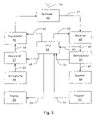
- FIG. 2 is a simplified block diagram of a base station on which an embodiment of the invention can be implemented
- FIG. 3 is a block diagram of a remote terminal on which an embodiment of the invention can be implemented.
- FIG. 4 is a table of superframe transmission showing the superframe of Table 1 and the corresponding BS groups, BS 0 through BS 7 that transmit for each frame of the superframe according to an embodiment of the invention.
- the present invention allows for changes in reuse and interference levels between bursts in the broadcast channel.
- the BCH is divided into different bursts within its superframe that are each sent with different levels of reuse.
- Different bursts can also be sent with different spatial parameters, for example, phase and amplitude between elements of a spatial diversity array.
- An F burst is sent by all base stations omni-directionally.
- a T burst is sent by all base stations using changes in the spatial parameters.
- the B bursts are sent by subsets of the base station with changes in the spatial parameters. This progression enhances user terminal reception while minimizing interference.
- FIG. 1 shows a process flow diagram for building and sending a sequence of broadcast channel (BCH) bursts in accordance with the present invention.
- BCH broadcast channel
- This process is described in the context of several base stations (BS), in a network that includes many base stations, sending a BCH superframe to any subscriber stations or remote user terminals that may be within range of the base stations.
- the superframe includes bursts that are designated for use by different groups of the base stations.
- the designation of superframes, frames, slots and subslots used here is for convenient reference purposes only. Each burst described below could be characterized as a subslot of a slot, a slot of a frame or some portion of a superframe as in the example embodiment described.
- the F burst is an identical burst at every base station and is selected to allow user terminals to perform frequency correction on their BCH reception.
- the F burst is transmitted as a pair of pure tones. This allows the tones to be slightly out of phase as they are received from two different base station and still be mixed by the receiver to obtain a reliable frequency reference.
- the base stations act almost as repeater stations so that the F burst penetrates the entire network. The particular content of the F burst is not significant but can relate to aspects of the BCH that are common to all base stations.
- the base stations can be synchronized in any of a variety of ways well-known in the art.
- a GPS signal can be used for example.
- the GPS signal has a benefit that it does not consume any frequency resources that could otherwise be used for traffic. Since the F burst is transmitted by all base stations at the same time, it corresponds to the highest level of interference added to the air waves, the communication resources of the system.
- the base stations all send a T burst 305 .
- the base stations can be synchronized in the same way as with the F burst.
- the T burst contains information regarding the base station color code (BSCC) of the transmitting base station, however, as with the F burst, information common to all base stations can be transmitted.
- the T burst can also be sent with varying spatial parameters. This may allow any user terminal that can receive the T burst simultaneously from different base stations to distinguish the different received bursts from each other. It also reduces the overall level of interference and noise injected into the system as compared to the F burst. In other embodiments, one of either the F burst or the T burst can be eliminated. While using both bursts configured as described helps the user terminal receive the next bursts, eliminating one or the other will further conserve frequency resources.
- the first B burst of the BCH is sent 307 .
- the B burst is also sent using varying spatial parameters. There are several B bursts and they are divided up between the base stations so that only a portion of the base stations use each B burst. In one embodiment, each base station only uses one B burst. This means that the reuse factor on the B bursts is equivalent to the number of B bursts. In the present embodiment there are eight B bursts so the reuse factor is eight. Any other number of B bursts can be used depending on the needs of a particular system configuration, the number of base station and the tendency of the base stations to interfere with one another.
- the B bursts can be allocated in any desired way.
- the B bursts can be allocated so that simultaneously transmitting base stations are as far apart from each other as possible. In one embodiment, this corresponds to the allocation of BSCC's.
- all of the BSCC's can be divided into eight groups and one of the eight B bursts can be assigned to each group of BSCC's. This approach has an added advantage that the BSCC can be used to identify B bursts from different base stations. Base stations simultaneously transmitting on the same B burst with the same BSCC will be a maximum distance apart.
- B bursts from different base stations are easier to distinguish, they can better carry information that is specific to a particular base station.
- This information can include a particular base station's BSCC, transmit power, traffic load, available frequency resources and allocations, hopping sequences, and any other desired information.
- the second group of base stations send the second B burst 309 .
- the third B burst of the BCH is sent from third BS group 311 .
- the fourth B burst of the BCH is sent from the fourth BS group 313 .
- the fifth B burst of the BCH is sent from the fifth BS group 315 .
- the sixth B burst of the BCH is sent from the sixth BS group 317 .
- the seventh B burst of the BCH is sent from the seventh BS group 319
- the eighth B burst of the BCH is sent from the eighth BS group 321 . This completes the superframe.
- the superframe can then be repeated by sending the F, T and B bursts again 323 as long as the system is in operation.
- the bursts are described as being of a certain number and being sent in a certain order, however, these factors can be modified to meet any particular system requirements. Since the frame is repeated, the precise ordering is less important, any type of burst can be sent first, B bursts can be interspersed between F and T bursts, and additional high or low reuse bursts can be added or removed from the superframe. The bursts may be sent immediately one after the other, or other bursts may be interspersed between the bursts.
- the bursts can be on a channel that is exclusively used for transmissions from base stations or it can be a duplexed channel used for both uplink and downlink. The number of B bursts can be varied to suit system needs as well.
- the F burst is a shared burst with a high level of interference.
- the T burst is a shared burst with a lower level of interference, and the B burst is a base station-specific burst with the lowest level of interference.
- the variations in reuse, interference generation and transmitted information can be varied to suit any particular application.
- communication sessions are initiated for each user terminal or remote terminal from the broadcast channel BCH which is transmitted as a burst from the base station to all potential user terminals.
- the BCH burst unlike the TCH (traffic channel) bursts, is transmitted in segments in many different directions where user terminals are likely to be, the specific beam pattern parameters will depend on the network.
- the BCH communicates enough basic information to enable the UT to gain access to the network by transmitting a message of its own, for example a subsequent exchange of a CR (configuration request) and a CM (configuration message) between the base station and the user terminal.
- the BCH also provides good frequency offset and timing update information to all user terminals, even when the BCH is not specifically directed toward any one user terminal in particular.
- the presently described embodiment has been selected in order to minimize the amount of information transmitted in the BCH as well as to minimize the bit rate.
- the broadcast channel information symbols provide the information needed for a user terminal to request a configuration message from the base station. They also provide information to guide user terminal handover decisions.
- the broadcast logical channel provides information that can be used by a UT (user terminal) to open a configuration channel (CCH) to the BS (base station). It also provides information to guide UT handover decisions for handovers to other base stations.
- the BCH logical channel can be located on a fixed RF (radio frequency) resource, e.g. a particular time slot and frequency, throughout the network of base stations.
- This fixed RF resource is, in one embodiment, dedicated to BCH and CCH, and is not used for RACH (random access channels) TCH (traffic channels) or other traffic.
- RACH random access channels
- TCH traffic channels
- the other slots which are not dedicated to BCH and CCH can be used for RACH, TCH or any other purpose.
- downlink slot 1 on an RF channel near the middle of the RF allocation is used for BCH and CCH functions. The particular choice of allocations will depend on the available resources and the requirements for overhead traffic.
- an RF allocation of 5 MHz is divided in frequency into 8 RF channels each of width 625 kHz.
- Each RF channel is divided in time into 5 ms frames.
- Each frame has 6 slots, 3 for receive and 3 for transmit, in a paired TDD (time-division duplex) arrangement.
- paired TDD time-division duplex
- the BCH can hop frequencies according to a predetermined scheme or be repeated on several different frequencies.
- the BCH is on its own channel and RACH and other overhead are on a separate control channel.
- one BCH can be provided on a constant frequency and a secondary BCH can be provided on another channel with hopping frequency. The particular details described here are not necessary to obtain the benefit of the invention and many variations are possible.
- each 5 ms frame has the following sequence of fields, where the uplink slots are receive slots used for communication from a user terminal (UT) to a base station (BS) and the downlink slots are transmit slots used for communication from the BS to the UT.:
- the BCH logical channel the first downlink slot in the example above, carries three burst types, called F, T, and B.
- the F and T bursts in the present example have a reuse of one. All base stations transmit them on the same carrier at the same time.
- the B burst has a reuse of eight.
- the superframe structure can be simplified as the following sequence: F T B 1 B 2 B 3 B 4 B 5 B 6 B 7 B 8 .
- One eighth of the base stations use broadcast slot B 5 , for example, while all the base stations use F and T.
- the repeating superframe structure is shown in more detail is shown in Table 1 below.
- the superframe has a period of 20 frames.
- even-numbered frames in the superframe are labeled “C” and carry CCH (configuration channel) bursts.
- Odd-numbered frames carry F, T, or B bursts.
- the F, T and B bursts are used differently by the base stations of the system. All base stations transmit F and T bursts at the same time in the appropriate frame, once every superframe.
- the base stations are all synchronized to a GPS (Global Positioning System) receiver reference timing so that they can all transmit at almost exactly the same time.
- GPS Global Positioning System
- the frame timing is established by the base stations that are in the area and transmitting on the RF carrier designated for the BCH.
- the carrier can be searched for or pre-programmed into the user terminals.
- the base stations, or base station if there is only one, can employ GPS or some other precise common timing reference to establish the frame timing.
- GPS timing offers the advantage that it is accurately synchronized and inexpensively available to all base stations. This allows the BCH to be shared by all the base stations with only a minimal guard time in the BCH between base stations. Precise timing also allows the remote terminals to make distance-based comparisons of the base stations for selection purposes.
- the F and T frames are occupied by all of the base stations on each repetition of the superframe. This is shown in the columns corresponding to frames 1 and 3 in the superframe of FIG. 4 . This corresponds to a reuse factor of 1, as can be seen in FIG. 4 in which each BS, BS 0 through BS 7 transmits the F and T bursts.
- the B frames labeled B 0 -B 7 , however, have a reuse factor of 8.
- the B frames are assigned to each base station based on its BSCC (Base Station Color Code), although any other assignment mechanism can be used, as can any other number of different B frames. This is shown in FIG.
- BSCC Base Station Color Code
- the column for each frame 5 , 7 , 9 , 11 , 13 , 15 , 17 , and 19 shows only transmitting BS.
- One benefit of assigning the B bursts is that the base stations that transmit simultaneously on the same burst will be separated from each other by at least one other base station. Accordingly, the identifiers BS 0 through BS 7 in FIG. 4 may each correspond to a single base station or to different groups of base stations.
- the base stations in group BS 5 in FIG. 4 are those that have any of the eight different BSCC's corresponding to 5 (mod 8) or 5, 13, 21, 29, 37, 45, 53, 61. These base stations transmit their B burst in frame 15 or frame B 5 of the superframe.
- a base station frequency hops, broadcasts BCH, listens for uplink CR, and sends downlink CM in response to CR.
- the BSCC can also be used by base stations and terminals to ensure that messages transmitted to and from one base station are not confused with messages transmitted to and from a neighboring base station.
- the BSCC is uniquely assigned. No base station should be able to routinely see user terminals that are communicating with a base station of the same color code. Likewise, no user terminal should be able to see two base stations that are assigned the same BSCC. A UT should never be in simultaneous communication range of two base stations that have the same BSCC.
- BSCC's that differ by a multiple of 8 can be assigned to non-adjacent base stations. This ensures that the frames labeled B 0 -B 7 in the superframe are received with minimal interference at a UT.
- the total number of base stations as well as the number of frames in a superframe, the of slots in a frame and the particular slots used for transmitting BCH bursts, CRs can be modified to suit particular applications.
- the F burst contains:
- the symbol period for all bursts is 2 ⁇ s (500,000 symbols per second). Bursts can be transmitted in QPSK (Quarternary Phase Shift Keying), so that the nominal occupied bandwidth is 625 kHz.
- QPSK Quadratternary Phase Shift Keying
- the 1056 ⁇ s of symbols contains frequency correction symbols that follow a known predictable pattern.
- the frequency correction symbols can be a mixture of two complex tones.
- the T burst in this example consists of a short preamble followed by 8 consecutive QPSK signals of length 64 symbols each.
- Each repeated signal is generated from a code word, such as a Walsh-Hadamard code word, determined as a function of the base station color code (BSCC).
- the 8 repetitions are scrambled using a scrambling sequence that does not depend on the BSCC. Any scrambling code can be used.
- a pseudorandom sequence provides overall consistent waveform properties when modulated and can be generated using any of a variety of ways well-known in the art.
- a scrambling sequence is generated from a congruential pseudorandom sequence generator.
- the T burst in this example is made up of:
- the preamble is a known sequence of symbols that are adjacent in the QPSK modulation format. A variety of different sequences can be used.
- the preamble sequence provides some additional ramp-up and guard time. The particular sequence will depend on the modulation format, the quality of the RF channels and other possible intended uses.
- the symbols t( 1 )-t( 512 ) are a function of the BSCC (base station color code).
- the symbols t( 1 )-t( 512 ) consist of 8 scrambled repetitions of the selected 64-bit Walsh-Hadamard or other type of code word using QPSK modulation. In one embodiment, each of the 8 scrambled repetitions is transmitted from the base station using a different beam pattern.
- the B burst in this example consists of a short preamble followed by 8 consecutive QPSK signals of length 64 symbols each.
- the signals are also modulated code words, such as Walsh-Hadamard code words.
- a single code word of length 64 is selected as a function of the BCH payload, and is repeated 8 times. Each repetition is scrambled using a linear feedback shift register initialized using a function of the base station color code.
- the spatial parameters for example transmit weights, used to transmit the last four segments of the B burst are the same as the spatial parameters used to transmit the first four segments.
- any phase change between, e.g., the 1st and 5th segments may be attributed to frequency offset. It's useful that there be a gap in time before the weights are repeated; a longer gap gives a more accurate frequency measurement but reduces the acquisition range of the frequency measurement.
- the 1st and 5th segments of the B burst are transmitted with the same spatial parameters, they are not identical signals. They contain the same Walsh-Hadamard code word scrambled differently.
- the B burst consists of:
- the preamble for the B burst is a known sequence of symbols that are adjacent in the QPSK modulation format.
- a variety of different sequences can be used. This sequence helps the UT establish timing. The particular sequence will depend on the modulation format, the quality of the RF channels and other possible intended uses.
- the symbols b( 1 )-b( 512 ) are a function of the base station color code BSCC, the base station transmit power bsTxPwr, and the base station load bsLoad. These symbols can be derived in a variety of different ways.
- a six-bit message is defined as p( 1 )-p( 6 ).
- the first four bits p( 1 )-p( 4 ) carry the base station transmit power field bsTxPwr.
- the last two bits carry the bsLoad field.
- the bsTxPwr fields encodes a power from 0-45 dBm in 3 dB steps.
- the BStxPwr can be the effective isotropic radiated power of the broadcast message. This number indicates the power transmitted by the base station taking into account the number of amplifiers and diversity antennas available at the base station.
- the bsLoad field encoded in p( 5 ) and p( 6 ), gives an indication of the current traffic load of the base station.
- BSload is the load on the base station, used by the user terminal to determine how frequently to send random access messages and whether to attempt access.
- BSload is an indication of the amount of unused capacity the base station has. It can be different from the number of active registered subscribers because subscribers can require different amounts of traffic capacity.
- BSload represents the transmit and receive bit rates of each modem of the base station over a period of a few minutes measured against maximum possible loading.
- the BSCC and BSload can be removed from the BCH burst.
- the BCH burst then contains only training or synchronization and BStxPwr, the only information directly related to handover decisions.
- the user terminal can still distinguish and compare different base stations for selection and handover decisions based on timing of the received BCH bursts.
- the user terminal can also direct its message requesting access based on timing.
- the two power levels can be distinguished by providing two different training sequences. This allows the BSTxPwr bits to be eliminated. For a single base station system, or if all base stations transmit with the same power, the BSTxPwr bits can also be deleted. If there is only one base station, it is not necessary to evaluate path loss but only whether the signal can be received. The rest of the network information can be learned upon registration.
- this can be used to select a code word, such as a Walsh-Hadamard code word, that will be used to encode the information together with the BSCC as a 64-bit sequence, h( 1 )-h( 64 ).
- the code word, h( 1 )-h( 64 ) is scrambled and transmitted as the symbols b( 1 )-b( 512 ).
- the symbols b( 1 )-b( 512 ) consist of 8 scrambled repetitions of the code word h( 1 )-h( 64 ) with QPSK modulation.
- the first four repetitions are transmitted from the base station using different beam patterns, and the last four repetitions use the same beam patterns as the first four in the same order. That is, repetitions 0 and 4 use the same beam pattern, repetitions 1 and 5 use the same beam pattern, and so on.
- the discontinuity in the BCH described above allows the BCH to be transmitted throughout the BS coverage area with minimal interference. However, it causes difficulties for the receiver.
- the modulation and coding structure of the broadcast burst therefore can be selected to aid the receiver in tolerating the phase and amplitude changes that occur between segments of the burst. This may be achieved in a number of ways.
- One way is to include training or pilot data symbols in each segment of the BCH. By comparing the received signal to the known training or pilot symbols, the receiver can estimate the gain and phase of each segment. The gain and phase can then be corrected to some nominal value (such as 1) across the entire received burst. The corrected burst can then be processed ignoring the phase or gain changes.
- pilot symbols expend signal energy that could otherwise be used to transmit information signals.
- the required number of symbols can be a very large fraction of the burst at the low SNRs (signal to noise ratios) at which a broadcast channel may operate.
- DPSK differential phase shift keying
- DPSK differential phase shift keying
- the differential receiver attempts to track phase changes during a segment.
- the transmitter transmits each segment using a fixed beam pattern.
- the phase does not change significantly during the segment.
- the use of the differential receiver to receive a message that does not significantly change in phase is wasteful since it degrades performance during the reception of each burst segment.
- Noncoherent modulation and coding Another way, which avoids pilot symbols and differential modulation, is to employ noncoherent modulation and coding. This approach does not require phase recovery at the receiver.
- the orthogonal signals may, for convenience, be defined by the rows of an orthogonal matrix H, where orthogonality means that H times its conjugate transpose H ⁇ * is a scaled identity matrix. If the entries of H further take values +1 or ⁇ 1, the signals may be transmitted using binary phase shift keying, which simplifies the transmitter and receiver.
- orthogonality means that H times its conjugate transpose H ⁇ * is a scaled identity matrix.
- the entries of H further take values +1 or ⁇ 1
- the signals may be transmitted using binary phase shift keying, which simplifies the transmitter and receiver.
- One such matrix H is the Walsh-Hadamard mentioned above.
- noncoherent orthogonal signaling formats There is a great variety of different noncoherent orthogonal signaling formats. Some formats also includes noncoherent signaling as a special case, such as PPM (pulse-position modulation) and FSK (frequency shift keying). While code word sets that are orthogonal and equal amplitude work very well for noncoherent signaling, these constraints can be greatly eased. The code words need only be sufficiently uncorrelated that they easily can be distinguished at the receiver. This will depend on the quality of the channel, of the transmitter and of the receiver.
- the present invention is implemented in an SDMA (Spatial Division Multiple Access) radio data communications system.
- each terminal is associated with a set of spatial parameters that relate to the radio communications channel between, for example, the base station and a user terminal.
- the spatial parameters comprise a spatial signature for each terminal.
- the RF energy from the base station can be more precisely directed at a single user terminal, reducing interference with and lowering the noise threshold for other user terminals.
- data received from several different user terminals at the same time can be resolved at lower receive energy levels.
- the spatial signatures can include such things as the spatial location of the transmitters, the directions-of-arrival (DOAs), times-of-arrival (TOAs) and the distance from the base station.
- DOAs directions-of-arrival
- TOAs times-of-arrival
- Estimates of parameters such as signal power levels, DOAs, and TOAs can be determined using known training sequences placed in digital data streams for the purpose of channel equalization in conjunction with sensor (antenna) array information. This information is then used to calculate appropriate weights for spatial demultiplexers, multiplexers, and combiners. Techniques well known in the art, can be used to exploit the properties of the training sequences in determining spatial parameters. Further details regarding the use of spatial division and SDMA systems are described, for example, in U.S. Pat. Nos. 5,828,658, issued Oct. 27, 1998 to Ottersten et al. and 5,642,353, issued Jun. 24, 1997 to Roy, III et al.
- SDMA time division multiple access
- FDMA frequency division multiple access
- CDMA code division multiple access
- FDD frequency division duplexing
- TDD time division duplexing
- FIG. 2 shows an example of a base station of a wireless communications system or network suitable for implementing the present invention.
- the base station uses SDMA technology which can be combined with other multiple access systems, such as time division multiple access (TDMA), frequency division multiple access (FDMA) and code division multiple access (CDMA). Multiple access can be combined with frequency division duplexing (FDD) or time division duplexing (TDD).
- the system or network includes a number of subscriber stations, also referred to as remote terminals or user terminals, such as that shown in FIG. 3 .
- the base station may be connected to a wide area network (WAN) through its host DSP 31 for providing any required data services and connections external to the immediate wireless system.
- WAN wide area network
- a plurality of antennas 3 is used to form an antenna array 4 , for example four antennas, although other numbers of antennas may be selected.
- Each antenna is an element of a four-element array 4 .
- a plurality of arrays are provided 4 - 1 , 4 - 2 , 4 - 3 .
- the antenna elements may have a spacing of from one-quarter to four wavelengths of a typical carrier frequency while the arrays may be separated by ten or twenty wavelengths. The best spacing for spatial diversity will depend upon the particular frequencies involved, the physical installation and other aspects of the system. In many applications, the spacing between antenna elements of each array can be less than two wavelengths of the received signal. The spacing between antenna arrays can be more than two wavelengths of the received signal.
- the spacing between elements in an array is selected to minimize grating lobes when transmissions from each element are coherently combined.
- the arrays are spaced apart so as to form a uniform array of elements. The distance between nearest elements in different arrays is the same as the spacing between elements within an array. As mentioned above, it is also possible for each array to have only a single element.
- a set of spatial multiplexing weights for each subscriber station are applied to the respective modulated signals to produce spatially multiplexed signals to be transmitted by the bank of four antennas.
- the host DSP 31 produces and maintains spatial signatures for each subscriber station for each conventional channel and calculates spatial multiplexing and demultiplexing weights using received signal measurements. In this manner, the signals from the current active subscriber stations, some of which may be active on the same conventional channel, are separated and interference and noise suppressed.
- an optimized multi-lobe antenna radiation pattern tailored to the current active subscriber station connections and interference situation is created.
- the channels used may be partitioned in any manner.
- the channels used may be partitioned as defined in the GSM (Global System for Mobile Communications) air interface, or any other time division air interface protocol, such as Digital Cellular, PCS (Personal Communication System), PHS (Personal Handyphone System) or WLL (Wireless Local Loop).
- GSM Global System for Mobile Communications
- PCS Personal Computer System
- PHS Personal Handyphone System
- WLL Wireless Local Loop
- continuous analog or CDMA channels can be used.
- the outputs of the antennas are connected to a duplexer switch 7 , which in a TDD embodiment, may be a time switch.
- a duplexer switch 7 which in a TDD embodiment, may be a time switch.
- Two possible implementations of the duplexer switch are as a frequency duplexer in a frequency division duplex (FDD) system, and as a time switch in a time division duplex (TDD) system.
- the antenna outputs are connected via the duplexer switch to a receiver 5 , and are converted down in analog by RF receiver (“RX”) modules 5 from the carrier frequency to an FM intermediate frequency (“IF”).
- RX RF receiver
- IF FM intermediate frequency
- ADCs analog to digital converters
- Final down-converting to baseband is carried out digitally.
- Digital filters can be used to implement the down-converting and the digital filtering, the latter using finite impulse response (FIR) filtering techniques. This is shown as block 13 .
- the invention can be adapted to suit a wide variety
- GSM Global System for Mobile Communications
- DSP digital signal processor
- ASIC Application Specific Integrated Circuit
- FPGA Field Programmable Gate Array
- timeslot processors 17 For TDMA signals, eight Motorola DSP56300 Family DSPs can be used as timeslot processors, one per receive timeslot.
- the timeslot processors 17 monitor the received signal power and estimate the frequency offset and time alignment. They also determine smart antenna weights for each antenna element. These are used in the SDMA scheme to determine a signal from a particular remote user and to demodulate the determined signal.
- the channels may be separated using codes in an FPGA and then further processed separately perhaps using separate DSPs for different users. Instead of being timeslot processors the processors are channel processors.
- the output of the timeslot processors 17 is demodulated burst data for each of the eight receive timeslots.
- This data is sent to the host DSP processor 31 whose main function is to control all elements of the system and interface with the higher level processing, which is the processing which deals with what signals are required for communications in all the different control and service communication channels defined in the system's communication protocol.
- the host DSP 31 can be a Motorola DSP56300 Family DSP.
- timeslot processors send the determined receive weights for each user terminal to the host DSP 31 .
- the host DSP 31 maintains state and timing information, receives uplink burst data from the timeslot processors 17 , and programs the timeslot processors 17 . In addition it decrypts, descrambles, checks error correcting code, and deconstructs bursts of the uplink signals, then formats the uplink signals to be sent for higher level processing in other parts of the base station.
- DSP 31 may include a memory element to store data, instructions, or hopping functions or sequences.
- the base station may have a separate memory element or have access to an auxiliary memory element.
- it formats service data and traffic data for further higher processing in the base station, receives downlink messages and traffic data from the other parts of the base station, processes the downlink bursts and formats and sends the downlink bursts to a transmit controller/modulator, shown as 37 .
- the host DSP also manages programming of other components of the base station including the transmit controller/modulator 37 and the RF timing controller shown as 33 .
- the RF controller 33 reads and transmits power monitoring and control values, controls the duplexer 7 and receives timing parameters and other settings for each burst from the host DSP 31 .
- the transmit controller/modulator 37 receives transmit data from the host DSP 31 .
- the transmit controller uses this data to produce analog IF outputs which are sent to the RF transmitter (TX) modules 39 .
- the received data bits are converted into a complex modulated signal, up-converted to an IF frequency, sampled, multiplied by transmit weights obtained from host DSP 31 , and converted via digital to analog converters (“DACs”) which are part of transmit controller/modulator 37 to analog transmit waveforms.
- DACs digital to analog converters
- the analog waveforms are sent to the transmit modules 39 .
- the transmit modules 39 up-convert the signals to the transmission frequency and amplify the signals.
- the amplified transmission signal outputs are sent to antennas 3 via the duplexer/time switch 7 .
- the signals may also be spread and scrambled using appropriate codes.
- FIG. 3 depicts an example component arrangement in a remote terminal that provides data or voice communication.
- the remote terminal's antenna 45 is connected to a duplexer 46 to permit the antenna 45 to be used for both transmission and reception.
- the antenna can be omni-directional or directional. For optimal performance, the antenna can be made up of multiple elements and employ spatial processing as discussed above for the base station. In an alternate embodiment, separate receive and transmit antennas are used eliminating the need for the duplexer 46 . In another alternate embodiment, where time division duplexing is used, a transmit/receive (TR) switch can be used instead of a duplexer as is well known in the art.
- the duplexer output 47 serves as input to a receiver 48 .
- the receiver 48 produces a down-converted signal 49 , which is the input to a demodulator 51 .
- a demodulated received sound or voice signal 67 is input to a speaker 66 .
- the remote terminal has a corresponding transmit chain in which data or voice to be transmitted is modulated in a modulator 57 .
- the modulated signal to be transmitted 59 output by the modulator 57 , is up-converted and amplified by a transmitter 60 , producing a transmitter output signal 61 .
- the transmitter output 61 is then input to the duplexer 46 for transmission by the antenna 45 .
- the demodulated received data 52 is supplied to a remote terminal central processing unit 68 (CPU) as is received data before demodulation 50 .
- the remote terminal CPU 68 can be implemented with a standard DSP (digital signal processor) device such as a Motorola series 56300 Family DSP. This DSP can also perform the functions of the demodulator 51 and the modulator 57 .
- the remote terminal CPU 68 controls the receiver through line 63 , the transmitter through line 62 , the demodulator through line 52 and the modulator through line 58 . It also communicates with a keyboard 53 through line 54 and a display 56 through line 55 .
- a microphone 64 and speaker 66 are connected through the modulator 57 and the demodulator 51 through lines 65 and 67 , respectively for a voice communications remote terminal.
- the microphone and speaker are also in direct communication with the CPU to provide voice or data communications.
- remote terminal CPU 68 may also include a memory element to store data, instructions, and hopping functions or sequences. Alternatively, the remote terminal may have a separate memory element or have access to an auxiliary memory element.
- the speaker 66 , and the microphone 64 are replaced or augmented by digital interfaces well-known in the art that allow data to be transmitted to and from an external data processing device (for example, a computer).
- the remote terminal's CPU is coupled to a standard digital interface such as a PCMCIA interface to an external computer and the display, keyboard, microphone and speaker are a part of the external computer.
- the remote terminal's CPU 68 communicates with these components through the digital interface and the external computer's controller.
- the microphone and speaker can be deleted.
- the keyboard and display can be deleted.
- the present invention includes various steps.
- the steps of the present invention may be performed by hardware components, such as those shown in FIGS. 2 and 3 , or may be embodied in machine-executable instructions, which may be used to cause a general-purpose or special-purpose processor or logic circuits programmed with the instructions to perform the steps.
- the steps may be performed by a combination of hardware and software.
- the steps have been described as being performed by either the base station or the user terminal. However, many of the steps described as being performed by the base station may be performed by the user terminal and vice versa.
- the invention is equally applicable to systems in which terminals communicate with each other without either one being designated as a base station, a user terminal, a remote terminal or a subscriber station.
- the present invention is equally applicable and useful in a peer-to-peer wireless network of communications devices using spatial processing.
- These devices may be cellular phones, PDA's, laptop computers, or any other wireless devices.
- these communications devices of wireless communications networks may be generally referred to as radios.
- the base station is described as performing spatial processing using adaptive antenna arrays.
- the user terminals can also contain antenna arrays, and can also perform spatial processing both on receiving and transmitting (uplink and downlink) within the scope of the present invention.
- each base station antenna array could be a part of a different base station.
- the base station's could share processing and transceiving functions.
- a central base station controller could perform many of the functions described above and use the antenna arrays of one or more base stations to transmit and receive signals.
- the present invention may be provided as a computer program product, which may include a machine-readable medium having stored thereon instructions, which may be used to program a computer (or other electronic devices) to perform a process according to the present invention.
- the machine-readable medium may include, but is not limited to, floppy diskettes, optical disks, CD-ROMs, and magneto-optical disks, ROMs, RAMs, EPROMs, EEPROMs, magnet or optical cards, flash memory, or other type of media/machine-readable medium suitable for storing electronic instructions.
- the present invention may also be downloaded as a computer program product, wherein the program may be transferred from a remote computer to a requesting computer by way of data signals embodied in a carrier wave or other propagation medium via a communication link (e.g., a modem or network connection).
- a communication link e.g., a modem or network connection
Landscapes
- Engineering & Computer Science (AREA)
- Computer Networks & Wireless Communication (AREA)
- Signal Processing (AREA)
- Mobile Radio Communication Systems (AREA)
Abstract
Description
| TABLE 1 | ||||||||||||||||||||
| |
1 | 2 | 3 | 4 | 5 | 6 | 7 | 8 | 9 | 10 | 11 | 12 | 13 | 14 | 15 | 16 | 17 | 18 | 19 | 20 |
| Uplink | C | C | C | C | C | C | C | C | C | C | ||||||||||
| Downlink | F | C | T | C | B0 | C | B1 | C | B2 | C | B3 | C | B4 | C | B5 | C | B6 | C | B7 | C |
bsTXPwr=3(p(1)+2p(2)+4p(3)+8p(4)) dBm. i.
Claims (32)
Priority Applications (2)
| Application Number | Priority Date | Filing Date | Title |
|---|---|---|---|
| US10/187,062 US7433347B1 (en) | 2002-06-28 | 2002-06-28 | Broadcast superframe with variable reuse and interference levels for a radio communications system |
| US12/245,670 US20090028128A1 (en) | 2002-06-28 | 2008-10-03 | Broadcast superframe with variable reuse and interference levels for a radio communications system |
Applications Claiming Priority (1)
| Application Number | Priority Date | Filing Date | Title |
|---|---|---|---|
| US10/187,062 US7433347B1 (en) | 2002-06-28 | 2002-06-28 | Broadcast superframe with variable reuse and interference levels for a radio communications system |
Related Child Applications (1)
| Application Number | Title | Priority Date | Filing Date |
|---|---|---|---|
| US12/245,670 Continuation US20090028128A1 (en) | 2002-06-28 | 2008-10-03 | Broadcast superframe with variable reuse and interference levels for a radio communications system |
Publications (1)
| Publication Number | Publication Date |
|---|---|
| US7433347B1 true US7433347B1 (en) | 2008-10-07 |
Family
ID=39797322
Family Applications (2)
| Application Number | Title | Priority Date | Filing Date |
|---|---|---|---|
| US10/187,062 Expired - Fee Related US7433347B1 (en) | 2002-06-28 | 2002-06-28 | Broadcast superframe with variable reuse and interference levels for a radio communications system |
| US12/245,670 Abandoned US20090028128A1 (en) | 2002-06-28 | 2008-10-03 | Broadcast superframe with variable reuse and interference levels for a radio communications system |
Family Applications After (1)
| Application Number | Title | Priority Date | Filing Date |
|---|---|---|---|
| US12/245,670 Abandoned US20090028128A1 (en) | 2002-06-28 | 2008-10-03 | Broadcast superframe with variable reuse and interference levels for a radio communications system |
Country Status (1)
| Country | Link |
|---|---|
| US (2) | US7433347B1 (en) |
Cited By (13)
| Publication number | Priority date | Publication date | Assignee | Title |
|---|---|---|---|---|
| US20100082885A1 (en) * | 2008-09-28 | 2010-04-01 | Ramot At Tel Aviv University Ltd. | Method and system for adaptive coding in flash memories |
| US20100103902A1 (en) * | 2007-06-19 | 2010-04-29 | Hak Seong Kim | Method of transmitting sounding reference signal |
| US20100135273A1 (en) * | 2007-03-29 | 2010-06-03 | Lg Electrinics Inc. | Method of transmitting sounding reference signal in wireless communication system |
| US20100182988A1 (en) * | 2007-08-14 | 2010-07-22 | Dong Wook Roh | Signal transmission method using cdm against the effect of channel estimation error in transmit diversity system |
| US20100284347A1 (en) * | 2007-08-14 | 2010-11-11 | Joon Kui Ahn | Method for acquiring resource region information for phich and method of receiving pdcch |
| US20110080968A1 (en) * | 2007-08-16 | 2011-04-07 | Dong Youn Seo | method for transmitting channel quality information in a multiple input multiple output system |
| US20110211510A1 (en) * | 2007-08-14 | 2011-09-01 | Hak Seong Kim | Method of transmitting data in a wireless communication system |
| US8315327B2 (en) | 2000-06-13 | 2012-11-20 | Aloft Media, Llc | Apparatus for transmitting a signal including transmit data to a multiple-input capable node |
| US8671327B2 (en) | 2008-09-28 | 2014-03-11 | Sandisk Technologies Inc. | Method and system for adaptive coding in flash memories |
| US8908607B2 (en) | 2012-10-31 | 2014-12-09 | Andrew Llc | Digital baseband transport in telecommunications distribution systems |
| US9385792B2 (en) | 2007-08-16 | 2016-07-05 | Lg Electronics Inc. | Method for transmitting codewords in multiple input multiple output system |
| US9826410B2 (en) | 2009-04-29 | 2017-11-21 | Commscope Technologies Llc | Distributed antenna system for wireless network systems |
| US20220159498A1 (en) * | 2017-05-12 | 2022-05-19 | Apple Inc. | Measurement Design for Next Radio (NR) and Long Term Evolution (LTE) |
Families Citing this family (9)
| Publication number | Priority date | Publication date | Assignee | Title |
|---|---|---|---|---|
| US7587485B1 (en) | 2002-09-19 | 2009-09-08 | Foundry Networks, Inc. | System and method for supplicant based accounting and access |
| US8179808B2 (en) * | 2003-10-31 | 2012-05-15 | Brocade Communication Systems, Inc. | Network path tracing method |
| JP4416008B2 (en) * | 2007-05-18 | 2010-02-17 | ソニー株式会社 | Communication apparatus and communication method |
| US8483161B2 (en) * | 2008-04-30 | 2013-07-09 | Lg Electronics Inc. | System information transmission method and subframe structure |
| EP4089928A1 (en) | 2011-07-28 | 2022-11-16 | Samsung Electronics Co., Ltd. | Apparatus and method for beamforming in wireless communication system |
| KR101820733B1 (en) * | 2011-08-24 | 2018-01-22 | 삼성전자주식회사 | Apparatus and method for selecting beam in wireless communication system |
| US9088496B2 (en) | 2012-03-16 | 2015-07-21 | Brocade Communications Systems, Inc. | Packet tracing through control and data plane operations |
| US9014013B2 (en) | 2012-03-16 | 2015-04-21 | Brocade Communications Systems, Inc. | Packet tracing through control and data plane operations using SNMP trap commands |
| US10979530B2 (en) | 2017-03-03 | 2021-04-13 | LGS Innovations LLC | Methods and apparatuses for batch radio resource command and control |
Citations (15)
| Publication number | Priority date | Publication date | Assignee | Title |
|---|---|---|---|---|
| US5446756A (en) * | 1990-03-19 | 1995-08-29 | Celsat America, Inc. | Integrated cellular communications system |
| US5649287A (en) | 1995-03-29 | 1997-07-15 | Telefonaktiebolaget Lm Ericsson | Orthogonalizing methods for antenna pattern nullfilling |
| US5648955A (en) * | 1993-11-01 | 1997-07-15 | Omnipoint Corporation | Method for power control in a TDMA spread spectrum communication system |
| US5732353A (en) * | 1995-04-07 | 1998-03-24 | Ericsson Inc. | Automatic control channel planning in adaptive channel allocation systems |
| US5787076A (en) * | 1993-11-01 | 1998-07-28 | Omnipoint Corporation | Multi-mode TDMA spread spectrum communication system |
| US5995832A (en) * | 1990-03-19 | 1999-11-30 | Celsat America, Inc. | Communications system |
| US6112094A (en) * | 1998-04-06 | 2000-08-29 | Ericsson Inc. | Orthogonal frequency hopping pattern re-use scheme |
| US6185440B1 (en) | 1997-12-10 | 2001-02-06 | Arraycomm, Inc. | Method for sequentially transmitting a downlink signal from a communication station that has an antenna array to achieve an omnidirectional radiation |
| US6298095B1 (en) * | 1998-04-03 | 2001-10-02 | Telefonaktiebolaget Lm Ericsson (Publ) | Communicating signaling information in a cellular system that has a tight frequency reuse pattern |
| US6359923B1 (en) * | 1997-12-18 | 2002-03-19 | At&T Wireless Services, Inc. | Highly bandwidth efficient communications |
| US6385457B1 (en) * | 1997-07-04 | 2002-05-07 | Telefonaktiebolaget Lm Ericsson (Publ) | Method and arrangement relating to radio communications systems |
| US6483826B1 (en) * | 1999-02-19 | 2002-11-19 | Telefonaktiebolaget Lm Ericsson (Publ) | Utilization of plural multiple access types for mobile telecommunications |
| US6560209B1 (en) * | 1997-02-06 | 2003-05-06 | At&T Wireless Services, Inc. | Method for frequency division duplex communications |
| US6600776B1 (en) * | 1997-02-24 | 2003-07-29 | At&T Wireless Services, Inc. | Vertical adaptive antenna array for a discrete multitone spread spectrum communications system |
| US20030166404A1 (en) * | 2001-11-15 | 2003-09-04 | Chuang Justin Che-I | Progressive reuse partitioning for improved interference rejection in wireless packet networks |
Family Cites Families (7)
| Publication number | Priority date | Publication date | Assignee | Title |
|---|---|---|---|---|
| US5257398A (en) * | 1990-02-27 | 1993-10-26 | Motorola, Inc. | Hopped-carrier dynamic frequency reuse |
| US5038399A (en) * | 1990-05-21 | 1991-08-06 | Motorola, Inc. | Method for assigning channel reuse levels in a multi-level cellular system |
| US5481533A (en) * | 1994-05-12 | 1996-01-02 | Bell Communications Research, Inc. | Hybrid intra-cell TDMA/inter-cell CDMA for wireless networks |
| US5844894A (en) * | 1996-02-29 | 1998-12-01 | Ericsson Inc. | Time-reuse partitioning system and methods for cellular radio telephone systems |
| US5870673A (en) * | 1996-08-30 | 1999-02-09 | Telefonaktiebolaget Lm Ericsson | Methods and systems for concurrent receipt of incoming calls from a wide area cellular network and a private radio communications network |
| US7567624B1 (en) * | 1999-07-30 | 2009-07-28 | Texas Instruments Incorporated | System and method of communicating using combined signal parameter diversity |
| US6778512B2 (en) * | 2000-12-20 | 2004-08-17 | Motorola, Inc. | Communication system that provides extra protection when transmitting critical data |
-
2002
- 2002-06-28 US US10/187,062 patent/US7433347B1/en not_active Expired - Fee Related
-
2008
- 2008-10-03 US US12/245,670 patent/US20090028128A1/en not_active Abandoned
Patent Citations (18)
| Publication number | Priority date | Publication date | Assignee | Title |
|---|---|---|---|---|
| US5446756A (en) * | 1990-03-19 | 1995-08-29 | Celsat America, Inc. | Integrated cellular communications system |
| US5995832A (en) * | 1990-03-19 | 1999-11-30 | Celsat America, Inc. | Communications system |
| US5648955A (en) * | 1993-11-01 | 1997-07-15 | Omnipoint Corporation | Method for power control in a TDMA spread spectrum communication system |
| US5787076A (en) * | 1993-11-01 | 1998-07-28 | Omnipoint Corporation | Multi-mode TDMA spread spectrum communication system |
| US5818820A (en) * | 1993-11-01 | 1998-10-06 | Omnipoint Corporation | Method and system for data link expansion or contraction using spread spectrum TDMA communication |
| US6112080A (en) * | 1993-11-01 | 2000-08-29 | Omnipoint Corporation | Wireless communication method and system |
| US5649287A (en) | 1995-03-29 | 1997-07-15 | Telefonaktiebolaget Lm Ericsson | Orthogonalizing methods for antenna pattern nullfilling |
| US5732353A (en) * | 1995-04-07 | 1998-03-24 | Ericsson Inc. | Automatic control channel planning in adaptive channel allocation systems |
| US6560209B1 (en) * | 1997-02-06 | 2003-05-06 | At&T Wireless Services, Inc. | Method for frequency division duplex communications |
| US6600776B1 (en) * | 1997-02-24 | 2003-07-29 | At&T Wireless Services, Inc. | Vertical adaptive antenna array for a discrete multitone spread spectrum communications system |
| US6385457B1 (en) * | 1997-07-04 | 2002-05-07 | Telefonaktiebolaget Lm Ericsson (Publ) | Method and arrangement relating to radio communications systems |
| US6185440B1 (en) | 1997-12-10 | 2001-02-06 | Arraycomm, Inc. | Method for sequentially transmitting a downlink signal from a communication station that has an antenna array to achieve an omnidirectional radiation |
| US6359923B1 (en) * | 1997-12-18 | 2002-03-19 | At&T Wireless Services, Inc. | Highly bandwidth efficient communications |
| US6480522B1 (en) * | 1997-12-18 | 2002-11-12 | At&T Wireless Services, Inc. | Method of polling second stations for functional quality and maintenance data in a discrete multitone spread spectrum communications system |
| US6298095B1 (en) * | 1998-04-03 | 2001-10-02 | Telefonaktiebolaget Lm Ericsson (Publ) | Communicating signaling information in a cellular system that has a tight frequency reuse pattern |
| US6112094A (en) * | 1998-04-06 | 2000-08-29 | Ericsson Inc. | Orthogonal frequency hopping pattern re-use scheme |
| US6483826B1 (en) * | 1999-02-19 | 2002-11-19 | Telefonaktiebolaget Lm Ericsson (Publ) | Utilization of plural multiple access types for mobile telecommunications |
| US20030166404A1 (en) * | 2001-11-15 | 2003-09-04 | Chuang Justin Che-I | Progressive reuse partitioning for improved interference rejection in wireless packet networks |
Cited By (56)
| Publication number | Priority date | Publication date | Assignee | Title |
|---|---|---|---|---|
| US9820209B1 (en) | 2000-06-13 | 2017-11-14 | Comcast Cable Communications, Llc | Data routing for OFDM transmissions |
| US8451928B2 (en) | 2000-06-13 | 2013-05-28 | Aloft Media, Llc | Apparatus for calculating weights associated with a first signal and applying the weights to a second signal |
| US10349332B2 (en) | 2000-06-13 | 2019-07-09 | Comcast Cable Communications, Llc | Network communication using selected resources |
| USRE45807E1 (en) | 2000-06-13 | 2015-11-17 | Comcast Cable Communications, Llc | Apparatus for transmitting a signal including transmit data to a multiple-input capable node |
| US10257765B2 (en) | 2000-06-13 | 2019-04-09 | Comcast Cable Communications, Llc | Transmission of OFDM symbols |
| USRE45775E1 (en) | 2000-06-13 | 2015-10-20 | Comcast Cable Communications, Llc | Method and system for robust, secure, and high-efficiency voice and packet transmission over ad-hoc, mesh, and MIMO communication networks |
| US9722842B2 (en) | 2000-06-13 | 2017-08-01 | Comcast Cable Communications, Llc | Transmission of data using a plurality of radio frequency channels |
| US8315327B2 (en) | 2000-06-13 | 2012-11-20 | Aloft Media, Llc | Apparatus for transmitting a signal including transmit data to a multiple-input capable node |
| US8315326B2 (en) | 2000-06-13 | 2012-11-20 | Aloft Media, Llc | Apparatus for generating at least one signal based on at least one aspect of at least two received signals |
| US9654323B2 (en) | 2000-06-13 | 2017-05-16 | Comcast Cable Communications, Llc | Data routing for OFDM transmission based on observed node capacities |
| US9197297B2 (en) | 2000-06-13 | 2015-11-24 | Comcast Cable Communications, Llc | Network communication using diversity |
| US9106286B2 (en) | 2000-06-13 | 2015-08-11 | Comcast Cable Communications, Llc | Network communication using diversity |
| US8451929B2 (en) | 2000-06-13 | 2013-05-28 | Aloft Media, Llc | Apparatus for calculating weights associated with a received signal and applying the weights to transmit data |
| US9209871B2 (en) | 2000-06-13 | 2015-12-08 | Comcast Cable Communications, Llc | Network communication using diversity |
| US9515788B2 (en) | 2000-06-13 | 2016-12-06 | Comcast Cable Communications, Llc | Originator and recipient based transmissions in wireless communications |
| US9401783B1 (en) | 2000-06-13 | 2016-07-26 | Comcast Cable Communications, Llc | Transmission of data to multiple nodes |
| US9391745B2 (en) | 2000-06-13 | 2016-07-12 | Comcast Cable Communications, Llc | Multi-user transmissions |
| US9356666B1 (en) | 2000-06-13 | 2016-05-31 | Comcast Cable Communications, Llc | Originator and recipient based transmissions in wireless communications |
| US9344233B2 (en) | 2000-06-13 | 2016-05-17 | Comcast Cable Communications, Llc | Originator and recipient based transmissions in wireless communications |
| US8363744B2 (en) | 2001-06-10 | 2013-01-29 | Aloft Media, Llc | Method and system for robust, secure, and high-efficiency voice and packet transmission over ad-hoc, mesh, and MIMO communication networks |
| US9300455B2 (en) | 2007-03-29 | 2016-03-29 | Lg Electronics Inc. | Method of transmitting sounding reference signal in wireless communication system |
| US9608786B2 (en) | 2007-03-29 | 2017-03-28 | Lg Electronics Inc. | Method of transmitting sounding reference signal in wireless communication system |
| US8831042B2 (en) | 2007-03-29 | 2014-09-09 | Lg Electronics Inc. | Method of transmitting sounding reference signal in wireless communication system |
| US20100135273A1 (en) * | 2007-03-29 | 2010-06-03 | Lg Electrinics Inc. | Method of transmitting sounding reference signal in wireless communication system |
| US20100103902A1 (en) * | 2007-06-19 | 2010-04-29 | Hak Seong Kim | Method of transmitting sounding reference signal |
| US8902876B2 (en) | 2007-06-19 | 2014-12-02 | Lg Electronics Inc. | Method of transmitting sounding reference signal |
| US8599819B2 (en) | 2007-06-19 | 2013-12-03 | Lg Electronics Inc. | Method of transmitting sounding reference signal |
| US8542697B2 (en) | 2007-08-14 | 2013-09-24 | Lg Electronics Inc. | Method of transmitting data in a wireless communication system |
| US8553668B2 (en) * | 2007-08-14 | 2013-10-08 | Lg Electronics Inc. | Signal transmission method using CDM against the effect of channel estimation error in transmit diversity system |
| US11064484B2 (en) | 2007-08-14 | 2021-07-13 | Lg Electronics Inc. | Method for acquiring resource region information for PHICH and method of receiving PDCCH |
| US8767634B2 (en) | 2007-08-14 | 2014-07-01 | Lg Electronics Inc. | Method for acquiring resource region information for PHICH and method of receiving PDCCH |
| US10117243B2 (en) | 2007-08-14 | 2018-10-30 | Lg Electronics Inc. | Method for acquiring resource region information for PHICH and method of receiving PDCCH |
| US8743819B2 (en) | 2007-08-14 | 2014-06-03 | Lg Electronics Inc. | Method for acquiring resource region information for PHICH and method of receiving PDCCH |
| US20100182988A1 (en) * | 2007-08-14 | 2010-07-22 | Dong Wook Roh | Signal transmission method using cdm against the effect of channel estimation error in transmit diversity system |
| US20110211510A1 (en) * | 2007-08-14 | 2011-09-01 | Hak Seong Kim | Method of transmitting data in a wireless communication system |
| US20100284347A1 (en) * | 2007-08-14 | 2010-11-11 | Joon Kui Ahn | Method for acquiring resource region information for phich and method of receiving pdcch |
| US9877319B2 (en) | 2007-08-14 | 2018-01-23 | Lg Electronics Inc. | Method for acquiring resource region information for PHICH and method of receiving PDCCH |
| US8351392B2 (en) | 2007-08-14 | 2013-01-08 | Lg Electronics Inc. | Method for acquiring resource region information for PHICH and method of receiving PDCCH |
| US9385792B2 (en) | 2007-08-16 | 2016-07-05 | Lg Electronics Inc. | Method for transmitting codewords in multiple input multiple output system |
| US8964878B2 (en) | 2007-08-16 | 2015-02-24 | Lg Electronics Inc. | Method for transmitting channel quality information in a multiple input multiple output system |
| US20110080968A1 (en) * | 2007-08-16 | 2011-04-07 | Dong Youn Seo | method for transmitting channel quality information in a multiple input multiple output system |
| US9148210B2 (en) | 2007-08-16 | 2015-09-29 | Lg Electronics Inc. | Method for transmitting channel quality information in a Multiple Input Multiple Output system |
| US8761286B2 (en) | 2007-08-16 | 2014-06-24 | Lg Electronics Inc. | Method for transmitting channel quality information in a multiple input multiple output system |
| US8671327B2 (en) | 2008-09-28 | 2014-03-11 | Sandisk Technologies Inc. | Method and system for adaptive coding in flash memories |
| US20100082885A1 (en) * | 2008-09-28 | 2010-04-01 | Ramot At Tel Aviv University Ltd. | Method and system for adaptive coding in flash memories |
| US8675417B2 (en) | 2008-09-28 | 2014-03-18 | Ramot At Tel Aviv University Ltd. | Method and system for adaptive coding in flash memories |
| US9826410B2 (en) | 2009-04-29 | 2017-11-21 | Commscope Technologies Llc | Distributed antenna system for wireless network systems |
| US10499253B2 (en) | 2009-04-29 | 2019-12-03 | Commscope Technologies Llc | Distributed antenna system for wireless network systems |
| US8908607B2 (en) | 2012-10-31 | 2014-12-09 | Andrew Llc | Digital baseband transport in telecommunications distribution systems |
| US9462603B2 (en) | 2012-10-31 | 2016-10-04 | Commscope Technologies Llc | Digital baseband transport in telecommunications distribution systems |
| US10841923B2 (en) | 2012-10-31 | 2020-11-17 | Commscope Technologies Llc | Digital baseband transport in telecommunications distribution systems |
| US9967885B2 (en) | 2012-10-31 | 2018-05-08 | Commscope Technologies Llc | Digital baseband transport in telecommunications distribution systems |
| US11419119B2 (en) | 2012-10-31 | 2022-08-16 | Commscope Technologies Llc | Digital baseband transport in telecommunications distribution systems |
| US20220159498A1 (en) * | 2017-05-12 | 2022-05-19 | Apple Inc. | Measurement Design for Next Radio (NR) and Long Term Evolution (LTE) |
| US11864016B2 (en) * | 2017-05-12 | 2024-01-02 | Apple Inc. | Measurement design for next radio (NR) and long term evolution (LTE) |
| US12532209B2 (en) | 2017-05-12 | 2026-01-20 | Apple Inc. | Measurement design for next radio (NR) and long term evolution (LTE) |
Also Published As
| Publication number | Publication date |
|---|---|
| US20090028128A1 (en) | 2009-01-29 |
Similar Documents
| Publication | Publication Date | Title |
|---|---|---|
| US6928287B2 (en) | Efficient broadcast channel structure and use for spatial diversity communications | |
| US20090028128A1 (en) | Broadcast superframe with variable reuse and interference levels for a radio communications system | |
| EP1552622B1 (en) | Assigning training sequences based on spatial channels in wireless communications system | |
| US7366223B1 (en) | Modifying hopping sequences in wireless networks | |
| US7606192B2 (en) | Transmitting signals on a channel used for traffic and access in a communications system | |
| EP1550238B1 (en) | Receiving signals on a channel used for traffic and access in a communications system | |
| US7349371B2 (en) | Selecting random access channels | |
| US8676267B2 (en) | Antenna systems with common overhead for CDMA base stations | |
| US6298095B1 (en) | Communicating signaling information in a cellular system that has a tight frequency reuse pattern | |
| US7164739B1 (en) | Broadcast burst with repeated weights for a radio communications system | |
| EP1520443B1 (en) | Hopping on random access channels | |
| WO1999060809A1 (en) | Coded allocation for sectorised radiocommunication systems | |
| US7339981B2 (en) | Shifted training sequences in a communications system | |
| US20040001539A1 (en) | Training using overhead data in a wireless communications network | |
| US7263082B1 (en) | Resolving user-specific narrow beam signals using a known sequence in a wireless communications system with a common pilot channel | |
| US7164726B1 (en) | Broadcast burst using spatial diversity for a radio communications system | |
| US7720161B1 (en) | Generating training sequences in a communications system |
Legal Events
| Date | Code | Title | Description |
|---|---|---|---|
| AS | Assignment |
Owner name: ARRAYCOMM, INC., CALIFORNIA Free format text: ASSIGNMENT OF ASSIGNORS INTEREST;ASSIGNORS:TROTT, MITCHELL D.;BOROS, TIBOR;REEL/FRAME:013410/0438;SIGNING DATES FROM 20020827 TO 20020916 |
|
| AS | Assignment |
Owner name: ARRAYCOMM LLC., CALIFORNIA Free format text: CORRECTIVE ASSIGNMENT TO CORRECT THE NATURE OF CONVEYANCE PREVIOUSLY RECORDED ON REEL 017088 FRAME 0957;ASSIGNOR:ARRAYCOMM, INC.;REEL/FRAME:021619/0597 Effective date: 20051114 |
|
| AS | Assignment |
Owner name: INTEL CORPORATION, CALIFORNIA Free format text: ASSIGNMENT OF ASSIGNORS INTEREST;ASSIGNOR:ARRAYCOMM LLC;REEL/FRAME:021794/0107 Effective date: 20081002 Owner name: INTEL CORPORATION,CALIFORNIA Free format text: ASSIGNMENT OF ASSIGNORS INTEREST;ASSIGNOR:ARRAYCOMM LLC;REEL/FRAME:021794/0107 Effective date: 20081002 |
|
| FEPP | Fee payment procedure |
Free format text: PAYOR NUMBER ASSIGNED (ORIGINAL EVENT CODE: ASPN); ENTITY STATUS OF PATENT OWNER: LARGE ENTITY |
|
| FPAY | Fee payment |
Year of fee payment: 4 |
|
| REMI | Maintenance fee reminder mailed | ||
| LAPS | Lapse for failure to pay maintenance fees | ||
| STCH | Information on status: patent discontinuation |
Free format text: PATENT EXPIRED DUE TO NONPAYMENT OF MAINTENANCE FEES UNDER 37 CFR 1.362 |
|
| STCH | Information on status: patent discontinuation |
Free format text: PATENT EXPIRED DUE TO NONPAYMENT OF MAINTENANCE FEES UNDER 37 CFR 1.362 |
|
| FP | Lapsed due to failure to pay maintenance fee |
Effective date: 20161007 |