US7350168B1 - System, method and computer program product for equivalence checking between designs with sequential differences - Google Patents
System, method and computer program product for equivalence checking between designs with sequential differences Download PDFInfo
- Publication number
- US7350168B1 US7350168B1 US11/129,238 US12923805A US7350168B1 US 7350168 B1 US7350168 B1 US 7350168B1 US 12923805 A US12923805 A US 12923805A US 7350168 B1 US7350168 B1 US 7350168B1
- Authority
- US
- United States
- Prior art keywords
- design
- differences
- sequential
- equivalency
- output
- Prior art date
- Legal status (The legal status is an assumption and is not a legal conclusion. Google has not performed a legal analysis and makes no representation as to the accuracy of the status listed.)
- Expired - Lifetime, expires
Links
Images


Classifications
-
- G—PHYSICS
- G06—COMPUTING OR CALCULATING; COUNTING
- G06F—ELECTRIC DIGITAL DATA PROCESSING
- G06F30/00—Computer-aided design [CAD]
- G06F30/30—Circuit design
- G06F30/32—Circuit design at the digital level
- G06F30/33—Design verification, e.g. functional simulation or model checking
- G06F30/3323—Design verification, e.g. functional simulation or model checking using formal methods, e.g. equivalence checking or property checking
Definitions
- the present invention relates to equivalence checking, and more particularly, to equivalence checking between designs.
- a system, method and computer program product are provided for equivalency checking between a first design and a second design having sequential differences.
- sequential differences between a first design and a second design are identified. It is then determined whether the first design and the second design are equivalent, utilizing the identified sequential differences.
- FIG. 1 illustrates a method for equivalency checking between a first design and a second design, in accordance with one embodiment.
- FIG. 2 illustrates an exemplary flow for equivalency checking between a first and second hardware design, in accordance with one embodiment.
- FIG. 3 illustrates a mapping among a first design and a second design, in accordance with one embodiment.
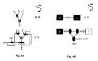
- FIG. 4A shows an exemplary difference in scheduling of computations among a first and second design, in accordance with one embodiment.
- FIG. 4B shows a micro-architecture difference, in accordance with one embodiment.
- FIG. 5 shows a transaction-accurate mapping, in accordance with one embodiment.
- FIG. 6 illustrates an exemplary computer system with which the equivalence checking may be carried out, in accordance with one embodiment.
- FIG. 1 illustrates a method 100 for equivalency checking between a first design and a second design, in accordance with one embodiment.
- first and second design may include any software and/or hardware designs that are different in any respect.
- the first design and the second design may differ with respect to a level of abstraction.
- the first design may include a specification design
- the second design may include an implementation design. Again, however, any software and/or hardware designs may be used that are different in any respect.
- sequential differences between the first design and the second design are identified.
- sequential differences may refer to any difference between the first and second design in terms of any aspect of timing, temporal characteristics, etc. associated with the architecture and/or functionality of the designs. Further, such identification of the sequential differences may be done in any desired manual and/or automated manner that is capable of identifying such differences.
- operation 104 it is then determined whether the first design and the second design are equivalent, utilizing the identified sequential differences.
- the term equivalent may refer to a situation where given two corresponding inputs (but not necessarily at the same point in time), the same output is produced (but not necessarily at the same point in time). Also, such determination of operation 104 may involve any desired manual and/or automated processing that is capable of determining whether at least one aspect of the first design and the second design are equivalent.
- the foregoing technique may be implemented in any desired environment.
- the method 100 may be used for equivalency checking with respect to a hardware environment where the first specification design may be a system level model (SLM) design, and the second implementation design may be a register transfer level (RTL) design.
- SLM system level model
- RTL register transfer level
- still other environments are contemplated such as RTL-RTL equivalency checking, as well as any other desired equivalency checking.
- FIG. 2 illustrates an exemplary flow 200 for equivalency checking between a first and second hardware design, in accordance with one embodiment.
- the flow 200 may be implemented in the context of the method 100 of FIG. 1 .
- the flow 200 may be carried out in any desired environment.
- a first and second design 202 , 204 may be input to logic 208 .
- the SLM design may, in one embodiment, include an abstract, functional model of a design that removes a lot of micro-architectural details present in an RTL design.
- the SLM design may, however, include a notion of a system-level clock that defines what happens in one system-level cycle.
- such design may also have a notion of concurrency and have functional units that are operating concurrently. So, in general, the logic 208 may expect a SLM that is timed, in at least one aspect.
- the SLM Since the SLM is timed, in one embodiment, it may be viewed as a finite-state machine (FSM) where the states may be defined by variables that persist from one system-level cycle to the next. In each system-level cycle, the FSM may compute some outputs based on current values of the inputs and the state of the FSM and may also update the state. Similarly, the RTL may be viewed as a FSM that works on an RTL clock. Thus, the RTL FSM may be a refinement of the SLM FSM and a single transition in the SLM FSM may correspond to a transition through a set of states in the RTL FSM.
- the logic 208 may handle multiple clocks, in one optional embodiment.
- sequential differences may be specified using any desired technique.
- sequential differences may be specified by using the notions of waveforms, constraints, maps and transactions.
- a waveform is a sequence of values. Waveforms can be transformed via temporal transformations to create new waveforms. The association of a waveform to a design signal creates a constraint. Maps provide a mechanism to specify the relationship between corresponding input signal pairs and output signal pairs. Both constraints and maps can be scoped with respect to transactions or can have global scope.
- first design and the second design 202 , 204 are equivalent by mapping inputs associated with the first design and the second design 202 , 204 utilizing the specified sequential differences.
- sequential differences between the first design and the second design 202 , 204 may be taken into account to determine a relationship among the inputs that are required for producing an equivalent output.
- the specified sequential differences may further involve a mapping among the outputs of the first design and the second design 202 , 204 .
- FIG. 3 illustrates such mapping among the first design and the second design 202 , 204 , in accordance with one embodiment.
- a first input mapping 302 and a second output mapping 304 are provided.
- such mapping may be used to determine whether outputs of the first design and the second design 202 , 204 are equivalent.
- the term equivalent may refer to a situation where given two corresponding inputs (but not necessarily at the same point in time), the corresponding output is produced (but not necessarily at the same point in time).
- the input sequences of the SLM and RTL are “corresponding” and not necessarily “identical,” since the RTL may have serial or fixed width parallel interfaces that accept data over multiple RTL cycles whereas the SLM may accept all of the data in one SLM cycle, etc.
- various outputs 210 may result. For example, if it is determined that the first design and the second design are equivalent, a proof of the equivalency may be output. On the other hand, if it is determined that the first design and the second design are not equivalent, a counter example may be output for illustrating the non-equivalency. Such counter example may be capable of being utilized for correcting the non-equivalency. More information regarding such output 210 will be set forth hereinafter in greater detail.
- sequential differences may refer to any difference between the first and second design in terms of any aspect of timing, temporal characteristics, etc. associated with the architecture and/or functionality of the designs.
- sequential differences may include a latency associated with the first design and the second design, a frequency at which inputs of the first design and the second design are sampled, a frequency at which outputs of the first design and the second design are produced, differences in a state mapping associated with the first design and the second design, and/or a protocol associated with the first design and the second design.
- Such protocol may include an input/output protocol.
- a first protocol of the first design may include a serial protocol
- a second protocol of the second design may include a parallel protocol.
- latency may refer to a number of cycles it takes for a design to process an input and produce an output based on that input.
- throughput may refer to the frequency at which the design samples its input or produces its output.
- Sequential differences may reflect any variety of differences between the first and second design.
- the sequential differences may reflect pipelining differences associated with the first design and the second design, differences in scheduling of computations associated with the first design and the second design, and/or micro-architecture differences associated with the first design and the second design. More information on such differences will be set forth hereinbelow in greater detail.
- Pipeline refinements include inserting or modifying the number of pipeline stages in data and control paths.
- Information on throughput and latency may be used by the equivalency checking logic 208 to align design interfaces and compare the designs for transactional equivalence.
- a common scenario might be to add a pipeline stage to a key datapath, increasing the implementation latency by one, followed by equivalency checking logic run to confirm that the longer pipeline still implements the original functional behavior.
- FIG. 4A shows an exemplary difference 400 in scheduling of computations among a first and second design, in accordance with one embodiment.
- the SLM design may perform a computation in parallel while the RTL design schedules operations in multiple cycles with a scheduling FSM.
- Such difference introduces additional states due to scheduling. Further, some operations that can use the same resource may become temporally disjointed, resulting in resource sharing.
- FIG. 4B shows a micro-architecture difference 450 , in accordance with one embodiment.
- a RTL has detailed micro-architectures like scan chains, sleep mode logic, clock gating, memory caches, bus-based communication along with bus arbitration, serial communication with handshakes, etc., all of which may constitute exemplary micro-architecture differences, which may result in sequential differences.
- a transaction may include the properties set forth in Table 1.
- TABLE 1 Encapsulates one or more units of computation for a block under consideration It is self-contained and cleans up any transient states that would interfere with the proper execution of the current or any future transactions
- Table 2 sets forth some additional examples of transactions, in accordance with one optional embodiment.
- DCT DCT for Transform
- one 8 ⁇ 8 block could be a transaction in the block: SLM and RTL FSMs, since this is the smallest unit of computation at the end of which the SLM and the RTL have outputs that are comparable.
- Microprocessor typically the SLM and RTL can be synchronized after the execution of individual instructions. Hence, the execution of one instruction could be a transaction. Also, a bigger transaction could be composed for a microprocessor by saying that a sequence of k instruction executions constitute one transaction. Such a bigger transaction for a microprocessor would be useful in verifying the interactions between instructions in the instruction pipeline in the RTL and showing that the pipelining does not alter the correctness of the execution of each individual instruction.
- Network processor a transaction could be the routing of a single packet from the input interface to the output.
- Memory A read or a write on a memory address.
- Specifying transaction does not necessarily require an understanding of the underlying state machines, but rather knowledge of when the machines can be compared in terms of their outputs or states. While a transaction may capture a subset of behaviors of a design, the transaction may be defined to include all interesting behaviors. In one exemplary trivial case where the SLM and RTL designs are identical state machines, the transaction may be one clock cycle.
- Table 3 illustrates exemplary information for specifying a transaction for an FSM.
- Output checks This specifies the condition when the output of the transaction is valid. It can also be viewed as specifying the end of the transaction, since the output/state is valid and comparable to that in the other model at the end of a transaction.
- FIG. 5 shows a transaction-accurate mapping 500 , in accordance with one embodiment.
- the equivalency checking logic may validate the equivalence of the models with respect to that transaction or generate a counter-example illustrating a scenario where the output/state check for the transaction fails to match, as mentioned previously.
- the equivalency checking logic verifies formally the equivalence of the SLM and RTL transactions.
- the notion of transaction allows the user to control the granularity at which the equivalence between the SLM and RTL is done and it allows for verification of a subset of the entire functionality in cases where verifying the entire functionality in one shot is not tractable.
- FIG. 6 illustrates an exemplary computer system 600 with which the equivalence checking may be carried out.
- a computer system 600 is provided including one or more processors, such as processor 601 , which is connected to a communication bus 602 .
- the computer system 600 also includes a main memory 604 .
- Control logic (software) and data are stored in the main memory 604 which may take the form of random access memory (RAM).
- the computer system 1100 also includes a display 1108 , i.e. a computer monitor, as well as any other unillustrated I/O devices.
- the computer system 600 may also include a secondary storage 610 .
- the secondary storage 610 includes, for example, a hard disk drive and/or a removable storage drive, representing a floppy disk drive, a magnetic tape drive, a compact disk drive, etc.
- the removable storage drive reads from and/or writes to a removable storage unit in a well known manner.
- Computer programs, or computer control logic algorithms may be stored in the main memory 604 and/or the secondary storage 610 . Such computer programs, when executed, enable the computer system 600 to perform various functions, including the above-described equivalency checking.
- Memory 604 and storage 610 are thus examples of computer-readable media.
- Appendix A sets for exemplary specifications for sequential differences. It should be strongly understood that such examples are set forth for illustrative purposes only and should not be construed as limiting in any manner whatsoever. Of course, any technique capable of specifying such sequential differences may be employed.
Landscapes
- Engineering & Computer Science (AREA)
- Computer Hardware Design (AREA)
- Physics & Mathematics (AREA)
- Theoretical Computer Science (AREA)
- Evolutionary Computation (AREA)
- Geometry (AREA)
- General Engineering & Computer Science (AREA)
- General Physics & Mathematics (AREA)
- Design And Manufacture Of Integrated Circuits (AREA)
Abstract
Description
| TABLE 1 |
| Encapsulates one or more units of computation for a block under |
| consideration |
| It is self-contained and cleans up any transient states that would interfere |
| with the proper execution of the current or any future transactions |
| TABLE 2 | |
| Discrete Cosine | the computation of DCT for |
| Transform (DCT) | one 8 × 8 block could be a transaction in the |
| block: | SLM and RTL FSMs, since this is the smallest unit |
| of computation at the end of which the SLM and | |
| the RTL have outputs that are comparable. | |
| Microprocessor: | typically the SLM and RTL can be synchronized |
| after the execution of individual instructions. Hence, | |
| the execution of one instruction could be a | |
| transaction. Also, a bigger transaction could be | |
| composed for a microprocessor by saying that a | |
| sequence of k instruction executions constitute one | |
| transaction. Such a bigger transaction for a | |
| microprocessor would be useful in verifying the | |
| interactions between instructions in the instruction | |
| pipeline in the RTL and showing that the pipelining | |
| does not alter the correctness of the execution of | |
| each individual instruction. | |
| Network processor: | a transaction could be the routing of a single packet |
| from the input interface to the output. | |
| Memory: | A read or a write on a memory address. |
| TABLE 3 | ||
| 1. | Reset: | There is a sequence of inputs that specify the |
| beginning of a transaction. For example, there | ||
| may be an explicit strobe signal that needs to go | ||
| high to indicate that a new DCT computation | ||
| is starting. This signal may initialize some | ||
| scheduling state machines to start accepting new | ||
| data and initialize the machine to perform the | ||
| DCT computation. | ||
| 2. | Constraints | These are constraints that need to be true during |
| and maps: | the execution of a transaction for the transaction | |
| to execute properly. These are constraints on | ||
| inputs that need to be asserted for the duration of | ||
| the transaction. | ||
| 3. | Ready-for-next- | This specifies when the next transaction |
| transaction | can start. In pipelined designs, transactions can | |
| condition: | overlap and hence new transactions can start | |
| before the previous one has ended. Also, in | ||
| situations where the delay of a transaction is | ||
| variable (dependent on the input data or some | ||
| internal state), then the design may have a signal | ||
| to indicate to the environment that it can accept a | ||
| new transaction. | ||
| 4. | Output checks: | This specifies the condition when the output of |
| the transaction is valid. It can also be viewed as | ||
| specifying the end of the transaction, since the | ||
| output/state is valid and comparable to that in the | ||
| other model at the end of a transaction. | ||
-
- create_constraint—Creates a constraint on an input port or adds a transactor to constrain a set of ports.
-
- create_constraint [-name <name>] -spec | -impl [-reset] [-transaction_scope |- global_scope]
- [-num_samples <num_samples>] { -waveform <waveform> | -module <module> }
- <port_description>
- -name <name>
- Name for the constraint. If not specified, a unique name is automatically generated. The name is returned as the result of the command. Wildcard substitution may be used to generate a list of names corresponding to ports in a wildcarded port description.
- -spec | -impl
- Associate this constraint with the specification or implementation design. This is required for transactor constraints.
- -reset
- Apply this constraint during reset. Otherwise the constraint is applied during normal operation.
- -transaction_scope | -global_scope
- If -transaction_scope, apply this constraint at the beginning of each transaction. This is the default. If -global_scope, apply this constraint once only beginning after reset. Constraint scoping is only appropriate for waveform-type constraints.
- -num_samples <num_samples>
- Number of samples to make per transaction. Defaults to the throughput of the design. This parameter should only be specified for waveform constraints.
- -waveform <waveform>
- Specify a waveform constraint and the name of a waveform used to constrain an input port.
- -module <module>
- Specify a transactor constraint and the name of a module from the cons library used to create a transactor instance.
- <port_description>
- If a waveform constraint, the name of the input port or black-box output constraint being constrained. Wildcarding may be used to generate a list of ports. If a transactor constraint, the port connection description of the module instance, using a Verilog style, either as an ordered port list or a list of named port connections.
- The create_constraint command constrains an input port by associating a waveform with the input port or constrains a set of ports by attaching a transactor module to the ports.
- Input ports may not be multiply constrained. Input ports constrained by transactors cannot be constrained or input mapped.
- The name of the created constraint is returned.
- create_constraint [-name <name>] -spec | -impl [-reset] [-transaction_scope |- global_scope]
-
- The create_constraint command constrains an input port by associating a waveform with the input port or constrains a set of ports by attaching a transactor to the ports.
-
- For a waveform constraint, the <port_description> refers to a single input port or a sub-field of an input port. If an input port, in, of the specification top module instance, is 16 bits wide, then spec.in [0] refers to the least significant bit of the port, and
- create_waveform -
name always_zero width 1 0+ - create_constraint -spec spec.in\[0\] waveform always_zero
- create_waveform -
- creates a constraint which constrains the least significant bit of the specification in port to a waveform which is always zero.
- By default, the constraint is applied with transaction scope. With transaction scope, the constraining waveform is restarted at the beginning of each transaction. With global scope, the constraint is applied once only and immediately after reset. Since transaction scope is the default scope, -transaction_scope is unnecessary, but may be used to explicitly document the intended scope.
- If -reset is specified, the constraint is applied during reset instead of during normal operation.
- Ports used only for reset should be constrained to non-reset values for normal operation to keep the design out of reset during equivalence checking.
- For a waveform constraint, the <port_description> refers to a single input port or a sub-field of an input port. If an input port, in, of the specification top module instance, is 16 bits wide, then spec.in [0] refers to the least significant bit of the port, and
-
- For a transactor constraint, a module is instantiated and waveforms are associated with the ports of the constraining module through the <port_description>. For example, consider the following Verilog module read into the constraints library:
- module mod256(out, in);
- output [15:0] out;
- input [15:0] in;
- assign out = {8′b0, in[7:0]};
- endmodule
- module mod256(out, in);
- The constraint command:
- create_constraint -name c_low -spec -module cons.mod256 { spec.in2 spec.in1}
- creates a constraint named c_low which constrains the waveform associated with the spec.in2 port to be the lower 8 bits of the waveform associated with spec.in1 port.
- create_map
- create_map—Maps a waveform, port or flop from the specification design to a waveform, port, or flop from the implementation design.
- For a transactor constraint, a module is instantiated and waveforms are associated with the ports of the constraining module through the <port_description>. For example, consider the following Verilog module read into the constraints library:
-
- create_map [-name <name>] [-transaction_scope | -global_scope] { -input | -output | -flop }
- [-num_samples <num_samples>] [-valid <valid>] <spec_waveform>
- <impl_waveform>
- -name <name>
- Name for the map being created. If not specified, a unique name is automatically generated. Wildcard substitution may be used to generate a list of names corresponding to matching pairs in a wildcarded description. The name or list of names is returned as the result of the command.
- -input | -output | -flop
- The type of map. Either input, output, or flop type must be specified.
- -transaction_scope
- Apply input constraints to this map at the beginning of each transaction. This is the default and only valid for input maps.
- -global_scope
- For input maps, apply input constraints to this map once only beginning after reset. This is only valid for input maps.
- -num_samples <num_samples>
- Number of samples to make per transaction. For input maps, defaults to the minimum throughput value of both designs. For output and flop maps, defaults to 1.
- -valid <valid>
- Guard the output check with the <valid> signal.
- <spec_waveform> <impl_waveform>
- Names of waveforms being mapped between designs. The order is not important. Wildcard substitution may be used to map more than one pair of waveforms or ports.
- The create_map command maps a waveform, port, or flop from the specification design to a waveform, port, or flop from the implementation design. Ports may be input or output ports which were not specified as clock ports or constrained input ports.
- The name of the map is returned.
- create_map [-name <name>] [-transaction_scope | -global_scope] { -input | -output | -flop }
-
- The create_map command is used to map inputs, outputs, or flops between designs.
-
- By default, mapped input waveforms are applied with transaction scope. With transaction scope, the mapped waveforms are restarted at the beginning of each transaction. With global scope, the waveforms are applied once only and immediately after reset. Global scope is valid only for input maps. Since transaction scope is the default scope, -transaction_scope is unnecessary, but may be used to explicitly document the intended scope.
- By default, input ports with the same name in both designs are implicitly mapped. Implicit maps are applied from the beginning cycle of a transaction with a default number of samples equal to the minimum throughput of the two designs. An implicit map may be removed using the unmap command.
- More complex relationships between ports are specified using waveforms. Waveforms may be used to aggregate or select portions of ports, to transform port values, or to shift or sample port values. For example, a 16 bit input port of the specification design could be mapped to two 8 bit input ports in the implementation design:
- create_waveform -name impl_in -aggregate {impl.in1 impl.in2}
- create_map -input spec.in impl_in
-
- Mapped output waveforms are compared with transaction scope. The mapped waveforms are restarted at the beginning of each transaction.
- By default, output ports with the same name in both designs are implicitly mapped. Implicit maps are compared output latency cycles after the beginning of a transaction.
- Sequentially different behavior can be captured by using appropriately created waveforms, for example:
- create_waveform -name spec_sample -
sample_freq 2 \- -sample_start 0 -sample_end 5 spec.data_out
- create_waveform -name impl_sample -
sample_freq 3 \- -sample_start 0 -sample_end 8 impl.data_out
- create_map -output -
num_samples 3 spec_sample impl_sample
- create_waveform -name spec_sample -
- This example compares two sampled outputs. The outputs are checked three times per transaction. The specification's data_out port is compared in
cycles cycles - The -valid option is used to produce conditional checks on the output map. For the previous example, replacing the map with:
- create_map -output -num_samples 3 -valid impl.valid
- spec_sample impl_sample
- will compare the sampled waveforms only in output check cycles when the impl.valid waveform is also high.
- Conditional checks may only be used when design throughput is 1, and the -valid waveform is sampled every cycle.
-
- By default, flops are compared with transaction scope. Flop inputs are compared in the beginning cycle of each transaction.
- By default, flop ports with the same hierarchical name in both designs are implicitly mapped. Implicit maps are compared in the beginning cycle of a transaction. An implicit map may be removed using the unmap command.
- See the create_state_encoding command for information on creating more complex maps between flops.
-
- create_state_encoding—Creates a state encoding relationship between state in one design and state in the other.
-
- create_state_encoding [-name <name>] -module <module> <port_list>
- -name <name>
- Name for the encoding. If not specified, a unique name is automatically generated. The name is returned as the result of the command.
- -module <module>
- Name of an encoding module from the cons library.
- <port_list>
- The port connection list for the module instance, using a Verilog style, either as an ordered port list or a list of named port connections.
- The create_state_encoding command establishes a combinational relationship between state in one design and state in the other design, for example, that binary-encoded state in one design is equivalent to one-hot encoded state in the other design.
- The name of the state encoding is returned.
-
- Sometimes flops do not map directly across the designs but have different encodings for the same state. For example, consider a case where the specification design has a two bit flop, spec. a, which needs to be mapped to a 4 bit flop, impl.b in the implementation design where impl.b represents the one-hot encoding of spec.a. The following combinational Verilog module represents the encoding relationship:
- module one_hot_encoder—4(in, out);
- input[1:0] in;
- output[3:0] out;
- assign out = { in[1] & in[0],
- in[1] & !in[0],
- !in[1] & in[0],
- !in [1] & !in[0]
- }
- endmodule
- module one_hot_encoder—4(in, out);
- The state encoding is established as:
- create_state_encoding -name one_hot one_hot_encoder—4 {spec.a impl.b}
- The following conditions must be met:
- The encoding module must be combinational.
- There must be at least one input and one output in the module, and all inputs must be associated with flops in one design, while all outputs must be associated with flops in the other design.
- Flops specified in the port list must be either all reset or all not reset in both designs. If all reset, the reset values should satisfy the state encoding.
- The types of the flops must exactly match the types specified in the encoding module's port list.
- Sometimes flops do not map directly across the designs but have different encodings for the same state. For example, consider a case where the specification design has a two bit flop, spec. a, which needs to be mapped to a 4 bit flop, impl.b in the implementation design where impl.b represents the one-hot encoding of spec.a. The following combinational Verilog module represents the encoding relationship:
-
- create_waveform—Creates a waveform by explicitly specifying a sequence of values or by transforming another waveform.
-
- create_waveform -name <name> [ -type <port> | -width <width> ]
- [-sample_freq <sample_freq>][-sample_start <sample_start>][-sample_end
- <sample_end>]
- [-hold_interval <hold_interval>][-hold_start <hold_start >][-hold_end
- <hold_end>]
- [-aggregate <waveform_list>] <source_waveform>
- -name <name>
- Name for the waveform being created. If not specified, a unique name is automatically generated. The name is returned as the result of the command.
- -type <port>
- For explicit waveforms, specifies this waveform's type to be the same type as the specified port.
- -width <width>
- For explicit waveforms, specifies a fixed bit width type.
- -sample_freq <sample_freq> -sample_start <sample_start> -sample_end
- <sample_end>
- For fixed sampling waveform transformations, the frequency, start, and end parameters which default to 1, 0, and infinity respectively.
- -hold_interval <hold_interval> -hold_start <hold_start> -hold_end <hold_end>
- For holding waveform transformations, the interval, start, and end holding parameters which default to 1, 0, and infinity respectively.
- -aggregate <waveform_list>
- For aggregate waveform transformations, a list of waveforms to aggregate. The bits of the first waveform in the list become the most significant bits of the aggregated waveform.
- <source_waveform>
- For explicit waveforms, a sequence of explicit waveform values. For waveform transformations, the source waveform.
- The create_waveform command creates a waveform form explicit values or from transformations or aggregations of other waveforms.
- Every port in the design has an implicit waveform associated with it which represents the sequence of values read or written by that port. In commands which use waveforms, the port name can be used to refer to this waveform.
- The name of the waveform is returned.
- create_waveform -name <name> [ -type <port> | -width <width> ]
-
- A waveform describes an infinite sequence of values of a specific type.
- The create_waveform command creates a waveform from explicit values or from transformations or aggregations of other waveforms.
- Every port of the design has an implicit waveform associated with it which represents the sequence of values read or written by that port. In commands which use waveforms, the port name is used to refer to this waveform.
-
- An explicit waveform is described using regular expressions, for example:
- create_waveform -name waveform0 -width 1 { 1 1 0+ }
- Waveform0 is high for two values and then low for all values thereafter. This waveform might describe a one-bit port being held high for two cycles followed by always low values. The name is optional. If not specified, a unique name is assigned by SLEC and returned as the command result.
- In addition to concrete values, SLEC has the notion of a symbolic value, S, which represents all possible values of the data type of the waveform. The
option width 1 specifies the data type of waveform0 to be a one bit value. So the symbolic value S for waveform0 represents 0 and 1. - All waveform sequences are infinite in length. 0+ at the end of the sequence means that 0 is to be repeated forever for waveform0. If the explicit sequence had a finite sequence of values, then SLEC appends an infinite sequence of symbolic values to complete the waveform. So the following waveforms are identical:
- create_waveform -name waveform1a -width 1 { 1 0 1 0 }
- create_waveform -name waveform1b -width 1 { 1 0 1 0 S }
- create_waveform -name waveform1c -width 1 { 1 0 1 0 S+ }
- A subset of values can be described using | and ^ operators. The | operator is used to specify a choice of values, and the ^ operator is used to specify any value except the specific value:
- create_waveform -name odd_only -width 3 { (1|3|5|7)+ }
- create_waveform -name one_non_zero -width 3 { ^0 0+ }
- A value type can be associated with each waveform. The type can be either a bit vector of fixed width, as in the previous example, or it is specified as the type associated with a port or previously defined waveform:
- create_waveform waveform2 -type spec.in0 { 3′
b110 3′b010 3′b000+ }
- create_waveform waveform2 -type spec.in0 { 3′
- where, in this example, port spec.in0 has a bit width of three.
- An explicit waveform is described using regular expressions, for example:
-
- A waveform can sample another waveform beginning in a start cycle repeating every frequency cycles until an end cycle using the following arguments:
- -sample_freq <sample_freq> -sample_start <sample_start> -sample_end
- <sample_end>
- Waveforms begin with
index 0. The default sample parameters are a start of 0, frequency of 1, and end of infinity. For example,- create_waveform -name waveform3 -sample_freq 2 -
sample_start 0 \- -
sample_end 10 spec.out
- -
- create_waveform -name waveform3 -sample_freq 2 -
- creates a waveform which samples the waveform associated with port spec. out starting with the value at
index 0, every 2 values, up toindex 10. The waveform is symbolic after that. - A waveform can sample and hold another waveform beginning in a source start cycle holding that value for an interval and repeating until a source end cycle is reached using the following arguments:
- {[-hold_interval <hold_interval> ][ -hold_start <hold_start> ][ -hold_end <hold_end> ] }
- For example,
- create_waveform -name waveform6 -hold_interval 2 -
hold_start 0 \- -hold_end 7 spec.in
- create_waveform -name waveform6 -hold_interval 2 -
- creates a waveform which holds the first value of the spec. in waveform for two cycles, holds the next seven values of spec. in for two cycles each, and becomes symbolic after that.
- If no starting cycle is specified, it defaults to
cycle 0. If no interval is specified, it defaults to 1 cycle. If no ending cycle is specified, the waveform is sampled forever.
-
- Another form of the create_waveform command is used to aggregate other waveforms into one waveform with aggregate type. This is commonly used to bundle individual ports into a combined bus waveform.
- The waveform list aggregates the waveforms from most-significant to least-significant values. For example,
- create_waveform -name waveform9 -aggregate \
- { impl.in3 impl.in2 impl.in1 impl.in0 }
- aggregates four single bit implementation input ports into a parallel four bit waveform with port in3 treated as the most significant value of the aggregate waveform.
Claims (26)
Priority Applications (1)
| Application Number | Priority Date | Filing Date | Title |
|---|---|---|---|
| US11/129,238 US7350168B1 (en) | 2005-05-12 | 2005-05-12 | System, method and computer program product for equivalence checking between designs with sequential differences |
Applications Claiming Priority (1)
| Application Number | Priority Date | Filing Date | Title |
|---|---|---|---|
| US11/129,238 US7350168B1 (en) | 2005-05-12 | 2005-05-12 | System, method and computer program product for equivalence checking between designs with sequential differences |
Publications (1)
| Publication Number | Publication Date |
|---|---|
| US7350168B1 true US7350168B1 (en) | 2008-03-25 |
Family
ID=39199351
Family Applications (1)
| Application Number | Title | Priority Date | Filing Date |
|---|---|---|---|
| US11/129,238 Expired - Lifetime US7350168B1 (en) | 2005-05-12 | 2005-05-12 | System, method and computer program product for equivalence checking between designs with sequential differences |
Country Status (1)
| Country | Link |
|---|---|
| US (1) | US7350168B1 (en) |
Cited By (12)
| Publication number | Priority date | Publication date | Assignee | Title |
|---|---|---|---|---|
| US20070093942A1 (en) * | 2002-06-03 | 2007-04-26 | Omnigon Technologies Ltd. | Method for solving waveform sequence-matching problems using multidimensional attractor tokens |
| US20070277068A1 (en) * | 2006-05-25 | 2007-11-29 | Pouarz Travis W | System and Method of State Point Correspondence with Constrained Function Determination |
| US20080209370A1 (en) * | 2005-12-20 | 2008-08-28 | Synopsys, Inc. | Formally proving the functional equivalence of pipelined designs containing memories |
| US20080229276A1 (en) * | 2007-03-14 | 2008-09-18 | Jana Koehler | Automatic composition of model transformations |
| US20090300563A1 (en) * | 2008-05-30 | 2009-12-03 | Synopsys, Inc. | Method and system for performing sequential equivalence checking on integrated circuit (ic) designs |
| US20120011481A1 (en) * | 2010-06-23 | 2012-01-12 | Pankaj Kumar Dwivedi | Hierarchical Finite State Machine Generation For Power State Behavior in an Electronic Design |
| US8423934B1 (en) * | 2010-02-22 | 2013-04-16 | Cadence Design Systems, Inc. | Model validation cockpit |
| US20140195785A1 (en) * | 2012-11-27 | 2014-07-10 | International Business Machines Corporation | Formal verification of a logic design |
| US9032339B2 (en) | 2013-03-06 | 2015-05-12 | Synopsys, Inc. | Ranking verification results for root cause analysis |
| US9201994B1 (en) | 2013-03-13 | 2015-12-01 | Calypto Design Systems, Inc. | Flexible power query interfaces and infrastructures |
| US9817929B1 (en) | 2014-06-04 | 2017-11-14 | Calypto Design Systems, Inc. | Formal verification using microtransactions |
| GB2572665A (en) * | 2018-04-05 | 2019-10-09 | Imagination Tech Ltd | Verification of hardware design for data transformation pipeline |
Citations (3)
| Publication number | Priority date | Publication date | Assignee | Title |
|---|---|---|---|---|
| US20020059481A1 (en) * | 1998-12-30 | 2002-05-16 | Patrick O. Nunally | Method and apparatus for a multimedia application specific processor |
| US20030217345A1 (en) * | 2002-05-20 | 2003-11-20 | Rochit Rajsuman | Event based IC test system |
| US20040054875A1 (en) * | 2002-09-13 | 2004-03-18 | Segelken Ross A. | Method and apparatus to execute an instruction with a semi-fast operation in a staggered ALU |
-
2005
- 2005-05-12 US US11/129,238 patent/US7350168B1/en not_active Expired - Lifetime
Patent Citations (3)
| Publication number | Priority date | Publication date | Assignee | Title |
|---|---|---|---|---|
| US20020059481A1 (en) * | 1998-12-30 | 2002-05-16 | Patrick O. Nunally | Method and apparatus for a multimedia application specific processor |
| US20030217345A1 (en) * | 2002-05-20 | 2003-11-20 | Rochit Rajsuman | Event based IC test system |
| US20040054875A1 (en) * | 2002-09-13 | 2004-03-18 | Segelken Ross A. | Method and apparatus to execute an instruction with a semi-fast operation in a staggered ALU |
Non-Patent Citations (5)
| Title |
|---|
| Cabodi, G. et al., "Sequential circuit diagnosis based on formal verification techniques", IEEE 1992., pp. 187-196. * |
| Corno, F. et al., "On the test of micorprocessor cores", IEEE, 2001. pp. 209-213. * |
| Corno, F. et al., "Verifying the equivalence of sequential circuits with benetic algorithms", IEEE, 1999. pp. 1293-1298. * |
| Corno, F., "Automatic test program generatin from RT-level microprocessor descriptions", IEEE. @002. pp. 1-6. * |
| Corno, F., et al., "Simulation based sequential equivalence checking of RTL VHDL", IEEE, 1999. pp. 351-354. * |
Cited By (23)
| Publication number | Priority date | Publication date | Assignee | Title |
|---|---|---|---|---|
| US20070093942A1 (en) * | 2002-06-03 | 2007-04-26 | Omnigon Technologies Ltd. | Method for solving waveform sequence-matching problems using multidimensional attractor tokens |
| US20080209370A1 (en) * | 2005-12-20 | 2008-08-28 | Synopsys, Inc. | Formally proving the functional equivalence of pipelined designs containing memories |
| US7836414B2 (en) * | 2005-12-20 | 2010-11-16 | Synopsys, Inc. | Formally proving the functional equivalence of pipelined designs containing memories |
| US20070277068A1 (en) * | 2006-05-25 | 2007-11-29 | Pouarz Travis W | System and Method of State Point Correspondence with Constrained Function Determination |
| US7546561B2 (en) * | 2006-05-25 | 2009-06-09 | International Business Machines Corporation | System and method of state point correspondence with constrained function determination |
| US20080229276A1 (en) * | 2007-03-14 | 2008-09-18 | Jana Koehler | Automatic composition of model transformations |
| US8042091B2 (en) * | 2007-03-14 | 2011-10-18 | International Business Machines Corporation | Automatic composition of model transformations |
| US20090300563A1 (en) * | 2008-05-30 | 2009-12-03 | Synopsys, Inc. | Method and system for performing sequential equivalence checking on integrated circuit (ic) designs |
| US8015521B2 (en) * | 2008-05-30 | 2011-09-06 | Synopsys, Inc. | Method and system for performing sequential equivalence checking on integrated circuit (IC) designs |
| US8423934B1 (en) * | 2010-02-22 | 2013-04-16 | Cadence Design Systems, Inc. | Model validation cockpit |
| US8943451B2 (en) * | 2010-06-23 | 2015-01-27 | Mentor Graphics Corporation | Hierarchical finite state machine generation for power state behavior in an electronic design |
| US20120011481A1 (en) * | 2010-06-23 | 2012-01-12 | Pankaj Kumar Dwivedi | Hierarchical Finite State Machine Generation For Power State Behavior in an Electronic Design |
| US20140195785A1 (en) * | 2012-11-27 | 2014-07-10 | International Business Machines Corporation | Formal verification of a logic design |
| US8918747B2 (en) * | 2012-11-27 | 2014-12-23 | International Business Machines Corporation | Formal verification of a logic design |
| US9032339B2 (en) | 2013-03-06 | 2015-05-12 | Synopsys, Inc. | Ranking verification results for root cause analysis |
| US10380300B1 (en) | 2013-03-13 | 2019-08-13 | Mentor Graphics Corporation | Flexible power query interfaces and infrastructures |
| US9201994B1 (en) | 2013-03-13 | 2015-12-01 | Calypto Design Systems, Inc. | Flexible power query interfaces and infrastructures |
| US9817929B1 (en) | 2014-06-04 | 2017-11-14 | Calypto Design Systems, Inc. | Formal verification using microtransactions |
| US10515168B1 (en) | 2014-06-04 | 2019-12-24 | Mentor Graphics Corporation | Formal verification using microtransactions |
| GB2572665A (en) * | 2018-04-05 | 2019-10-09 | Imagination Tech Ltd | Verification of hardware design for data transformation pipeline |
| GB2572665B (en) * | 2018-04-05 | 2020-07-08 | Imagination Tech Ltd | Verification of hardware design for data transformation pipeline |
| US10719646B2 (en) | 2018-04-05 | 2020-07-21 | Imagination Technologies Limited | Verification of hardware design for data transformation pipeline with equivalent data transformation element output constraint |
| US10984162B2 (en) | 2018-04-05 | 2021-04-20 | Imagination Technologies Limited | Verification of hardware design for data transformation pipeline with equivalent data transformation element output constraint |
Similar Documents
| Publication | Publication Date | Title |
|---|---|---|
| Marshall et al. | Miracle: Micro-architectural leakage evaluation | |
| US7962886B1 (en) | Method and system for generating design constraints | |
| US7647572B1 (en) | Managing formal verification complexity of designs with multiple related counters | |
| US7350168B1 (en) | System, method and computer program product for equivalence checking between designs with sequential differences | |
| US7472361B2 (en) | System and method for generating a plurality of models at different levels of abstraction from a single master model | |
| Urdahl et al. | Path predicate abstraction for sound system-level models of RT-level circuit designs | |
| US5966306A (en) | Method for verifying protocol conformance of an electrical interface | |
| Kondratyev et al. | Checking delay-insensitivity: 10/sup 4/gates and beyond | |
| US20250103789A1 (en) | Techniques for modeling and verification of convergence for hierarchical domain crossings | |
| US20160300009A1 (en) | System and method for reactive initialization based formal verification of electronic logic design | |
| Pierre et al. | A tractable and fast method for monitoring SystemC TLM specifications | |
| US20110184714A1 (en) | Methods and Systems for Analyzing Electronic Design and Validation Models | |
| JP2008511894A (en) | Method and system for designing a structure level description of an electronic circuit | |
| Ara et al. | A proposal for transaction-level verification with component wrapper language | |
| Skarman et al. | Enhancing compiler-driven HDL design with automatic waveform analysis | |
| Bombieri et al. | Reusing RTL assertion checkers for verification of SystemC TLM models | |
| Herdt et al. | Towards fully automated TLM-to-RTL property refinement | |
| Boniol et al. | Identification of multi-core interference | |
| US9344408B2 (en) | Cloud-basd digital verification system and method | |
| CN117725866B (en) | A verification method, device, electronic device and readable storage medium | |
| CN116157799A (en) | Dynamic CDC verification method | |
| Keating | The simple art of SoC design: closing the gap between RTL and ESL | |
| Tripakis et al. | Tokens vs. signals: On conformance between formal models of dataflow and hardware | |
| US8090564B1 (en) | Automatic generation of transaction level bus simulation instructions from bus protocol | |
| US8813005B1 (en) | Debugging using tagged flip-flops |
Legal Events
| Date | Code | Title | Description |
|---|---|---|---|
| AS | Assignment |
Owner name: CALYPTO DESIGN SYSTEMS, INC., CALIFORNIA Free format text: ASSIGNMENT OF ASSIGNORS INTEREST;ASSIGNORS:MATHUR, ANMOL;SHARMA, NIKHIL;GOYAL, DEEPAK;AND OTHERS;REEL/FRAME:016573/0023;SIGNING DATES FROM 20050511 TO 20050512 |
|
| STCF | Information on status: patent grant |
Free format text: PATENTED CASE |
|
| AS | Assignment |
Owner name: SILICON VALLEY BANK, CALIFORNIA Free format text: SECURITY AGREEMENT;ASSIGNOR:CALYPTO DESIGN SYSTEMS, INC.;REEL/FRAME:021773/0206 Effective date: 20081031 |
|
| FPAY | Fee payment |
Year of fee payment: 4 |
|
| AS | Assignment |
Owner name: CALYPTO DESIGN SYSTEMS, INC., CALIFORNIA Free format text: RELEASE;ASSIGNOR:SILICON VALLEY BANK;REEL/FRAME:026803/0962 Effective date: 20110819 |
|
| FEPP | Fee payment procedure |
Free format text: PAYOR NUMBER ASSIGNED (ORIGINAL EVENT CODE: ASPN); ENTITY STATUS OF PATENT OWNER: LARGE ENTITY |
|
| FEPP | Fee payment procedure |
Free format text: PAT HOLDER NO LONGER CLAIMS SMALL ENTITY STATUS, ENTITY STATUS SET TO UNDISCOUNTED (ORIGINAL EVENT CODE: STOL); ENTITY STATUS OF PATENT OWNER: LARGE ENTITY |
|
| FPAY | Fee payment |
Year of fee payment: 8 |
|
| AS | Assignment |
Owner name: MENTOR GRAPHICS CORPORATION, OREGON Free format text: ASSIGNMENT OF ASSIGNORS INTEREST;ASSIGNOR:CALYPTO DESIGN SYSTEMS, INC.;REEL/FRAME:047766/0077 Effective date: 20150930 |
|
| MAFP | Maintenance fee payment |
Free format text: PAYMENT OF MAINTENANCE FEE, 12TH YEAR, LARGE ENTITY (ORIGINAL EVENT CODE: M1553); ENTITY STATUS OF PATENT OWNER: LARGE ENTITY Year of fee payment: 12 |
|
| AS | Assignment |
Owner name: SIEMENS INDUSTRY SOFTWARE INC., TEXAS Free format text: MERGER AND CHANGE OF NAME;ASSIGNORS:MENTOR GRAPHICS CORPORATION;SIEMENS INDUSTRY SOFTWARE INC.;REEL/FRAME:056597/0234 Effective date: 20201230 |