US7342370B2 - Electronic control system with torque and/or speed boost for motor vehicle seats - Google Patents
Electronic control system with torque and/or speed boost for motor vehicle seats Download PDFInfo
- Publication number
- US7342370B2 US7342370B2 US11/370,266 US37026606A US7342370B2 US 7342370 B2 US7342370 B2 US 7342370B2 US 37026606 A US37026606 A US 37026606A US 7342370 B2 US7342370 B2 US 7342370B2
- Authority
- US
- United States
- Prior art keywords
- motor
- desired profile
- power
- profile includes
- less
- Prior art date
- Legal status (The legal status is an assumption and is not a legal conclusion. Google has not performed a legal analysis and makes no representation as to the accuracy of the status listed.)
- Expired - Fee Related
Links
Images


Classifications
-
- B—PERFORMING OPERATIONS; TRANSPORTING
- B60—VEHICLES IN GENERAL
- B60N—SEATS SPECIALLY ADAPTED FOR VEHICLES; VEHICLE PASSENGER ACCOMMODATION NOT OTHERWISE PROVIDED FOR
- B60N2/00—Seats specially adapted for vehicles; Arrangement or mounting of seats in vehicles
- B60N2/02—Seats specially adapted for vehicles; Arrangement or mounting of seats in vehicles the seat or part thereof being movable, e.g. adjustable
- B60N2/0224—Non-manual adjustments, e.g. with electrical operation
- B60N2/0244—Non-manual adjustments, e.g. with electrical operation with logic circuits
-
- B—PERFORMING OPERATIONS; TRANSPORTING
- B60—VEHICLES IN GENERAL
- B60N—SEATS SPECIALLY ADAPTED FOR VEHICLES; VEHICLE PASSENGER ACCOMMODATION NOT OTHERWISE PROVIDED FOR
- B60N2/00—Seats specially adapted for vehicles; Arrangement or mounting of seats in vehicles
- B60N2/02—Seats specially adapted for vehicles; Arrangement or mounting of seats in vehicles the seat or part thereof being movable, e.g. adjustable
- B60N2/0224—Non-manual adjustments, e.g. with electrical operation
- B60N2/02246—Electric motors therefor
-
- B—PERFORMING OPERATIONS; TRANSPORTING
- B60—VEHICLES IN GENERAL
- B60N—SEATS SPECIALLY ADAPTED FOR VEHICLES; VEHICLE PASSENGER ACCOMMODATION NOT OTHERWISE PROVIDED FOR
- B60N2/00—Seats specially adapted for vehicles; Arrangement or mounting of seats in vehicles
- B60N2/02—Seats specially adapted for vehicles; Arrangement or mounting of seats in vehicles the seat or part thereof being movable, e.g. adjustable
- B60N2/0224—Non-manual adjustments, e.g. with electrical operation
- B60N2/0244—Non-manual adjustments, e.g. with electrical operation with logic circuits
- B60N2/0276—Non-manual adjustments, e.g. with electrical operation with logic circuits reaction to emergency situations, e.g. crash
-
- H—ELECTRICITY
- H02—GENERATION; CONVERSION OR DISTRIBUTION OF ELECTRIC POWER
- H02P—CONTROL OR REGULATION OF ELECTRIC MOTORS, ELECTRIC GENERATORS OR DYNAMO-ELECTRIC CONVERTERS; CONTROLLING TRANSFORMERS, REACTORS OR CHOKE COILS
- H02P1/00—Arrangements for starting electric motors or dynamo-electric converters
- H02P1/16—Arrangements for starting electric motors or dynamo-electric converters for starting dynamo-electric motors or dynamo-electric converters
- H02P1/18—Arrangements for starting electric motors or dynamo-electric converters for starting dynamo-electric motors or dynamo-electric converters for starting an individual DC motor
- H02P1/22—Arrangements for starting electric motors or dynamo-electric converters for starting dynamo-electric motors or dynamo-electric converters for starting an individual DC motor in either direction of rotation
-
- H—ELECTRICITY
- H02—GENERATION; CONVERSION OR DISTRIBUTION OF ELECTRIC POWER
- H02P—CONTROL OR REGULATION OF ELECTRIC MOTORS, ELECTRIC GENERATORS OR DYNAMO-ELECTRIC CONVERTERS; CONTROLLING TRANSFORMERS, REACTORS OR CHOKE COILS
- H02P7/00—Arrangements for regulating or controlling the speed or torque of electric DC motors
- H02P7/06—Arrangements for regulating or controlling the speed or torque of electric DC motors for regulating or controlling an individual DC dynamo-electric motor by varying field or armature current
- H02P7/18—Arrangements for regulating or controlling the speed or torque of electric DC motors for regulating or controlling an individual DC dynamo-electric motor by varying field or armature current by master control with auxiliary power
- H02P7/24—Arrangements for regulating or controlling the speed or torque of electric DC motors for regulating or controlling an individual DC dynamo-electric motor by varying field or armature current by master control with auxiliary power using discharge tubes or semiconductor devices
- H02P7/28—Arrangements for regulating or controlling the speed or torque of electric DC motors for regulating or controlling an individual DC dynamo-electric motor by varying field or armature current by master control with auxiliary power using discharge tubes or semiconductor devices using semiconductor devices
- H02P7/285—Arrangements for regulating or controlling the speed or torque of electric DC motors for regulating or controlling an individual DC dynamo-electric motor by varying field or armature current by master control with auxiliary power using discharge tubes or semiconductor devices using semiconductor devices controlling armature supply only
- H02P7/29—Arrangements for regulating or controlling the speed or torque of electric DC motors for regulating or controlling an individual DC dynamo-electric motor by varying field or armature current by master control with auxiliary power using discharge tubes or semiconductor devices using semiconductor devices controlling armature supply only using pulse modulation
-
- B—PERFORMING OPERATIONS; TRANSPORTING
- B60—VEHICLES IN GENERAL
- B60N—SEATS SPECIALLY ADAPTED FOR VEHICLES; VEHICLE PASSENGER ACCOMMODATION NOT OTHERWISE PROVIDED FOR
- B60N2210/00—Sensor types, e.g. for passenger detection systems or for controlling seats
- B60N2210/10—Field detection presence sensors
- B60N2210/14—Inductive; Magnetic field
Definitions
- the present invention generally relates to a system and method for controlling motor vehicle seats and, more particularly, to a system and method for controlling motors that boosts the speed and/or torque output of the motors.
- motor vehicles often have powered seats, powered adjustable pedals, powered windows, powered sun roofs, powered doors, and/or powered lift or tail gates. Each of these devices is typically operated by DC motors.
- Powered motor vehicle seats often are adjustable in several directions such as, for example, in a forward/rearward direction and a vertical direction. The user typically engages a switch that activates the motor to move the seat in the desired direction and releases the switch to deactivate the motor when the seat reaches a desired location.
- While these devices may provide adequate results in adjusting the seats, the movement can be undesirably slow at times. For example, movement can be undesirably slow when the user desires to move the seat an extended distance, when the seat is moved for ingress or egress of the user, and/or when the seat automatically moves to better protect the occupant if an imminent crash of the motor vehicle is detected by sensors.
- the relatively slower movement of the seat is desirable during normal operation of the seat so that the user can make fine adjustments to the seat position.
- the different speeds could be obtained by utilizing multi-speed motors, multiple motors, and/or larger motors but there is an ongoing desire in the industry to reduce size, weight, and/or cost of these devices. Accordingly, there is a need in the art for an improved system and method for controlling motor vehicle seats.
- a motor vehicle seat adjuster comprises, in combination, a DC motor, and a control system operably connected to the motor to control seat motion to a desired profile.
- Power to the motor is variable from less than 100% of normal power to greater than 100% of normal power. Controlling seat motion to a desired profile can give the occupant the sense and feel of luxury as well as a smoother more controlled ride.
- a motor vehicle seat adjuster comprising, in combination, a DC motor, and a control system operably connected to the motor to control seat motion to a desired profile. Parameters of the profile are customizable.
- motor vehicle seat adjuster comprises, in combination, a DC motor and a control system operably connected to the motor to control seat motion to a desired profile.
- the desired profile includes a starting power of about 0% to about 50% full power, a normal operating power of about 90% to about 100% of full power, and a boost operating power of at least about 180% of full power.
- the desired profile also includes an activation start time in the range of 10 ms to 500 ms, a soft start time in the range of about 10 ms to about 500 ms, a ramp up of about 0% to about 10% per 5 ms, a regulation response time of less than or equal to about 250 ms, a regulation overshoot of less than or equal to +/ ⁇ 25%, a regulation band less than or equal to +/ ⁇ 10%, a coast time of less than or equal to about 200 ms, position overshoot of less than or equal to about 2 mm displacement, a ramp down of about 0% to about 10% per 5 ms, and a normal operating speed of about 5 mm/s to about 50 mm/s.
- FIG. 1 is a perspective view of a powered seat assembly for a motor vehicle according to a preferred embodiment of the present invention
- FIG. 2 is a schematic view of a control system for a motor of the seat assembly of FIG. 1 where a high-side to a motor is boosted;
- FIG. 3 is a schematic view of an equivalent circuit showing the boost function of the control system of FIG. 2 ;
- FIG. 4 is a schematic view of an equivalent circuit showing an energy storage phase of the circuit of FIG. 3 ;
- FIG. 5 is a schematic view of an equivalent circuit showing the an energy transfer phase of the circuit of FIG. 3 ;
- FIG. 6 is a schematic view of an alternative boost circuit where a low-side to the motor is boosted
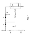
- FIG. 7 is a schematic view of an equivalent circuit showing the energy storage phase of the circuit of FIG. 6 ;
- FIG. 8 is a schematic view of an equivalent circuit showing the energy transfer phase of the circuit of FIG. 6 ;
- FIG. 9 is a table showing a speed of operation for the seat assembly of FIG. 1 ;
- FIG. 10 is a graphic view of a seat motion profile for the seat assembly of FIG. 1 ;
- FIG. 11 is a graphic view of a motor current profile comparing a seat assembly with and without the present invention.
- FIG. 12 is a schematic view of an equivalent circuit showing a full-bridge boost controller
- FIG. 13 is a graphic view of performance data for a DC brushed motor typically used in motor vehicle seat systems
- FIG. 14 is a diagrammatic view of a powered seat assembly for a motor vehicle having a customizable motion profile according to the present invention.
- FIG. 15 is a diagrammatic view of a system development tool for the powered seat assembly according to the present invention wherein a systems status screen is shown;
- FIG. 16 is a diagrammatic view of a configuration screen of the system development tool of FIG. 15 ;
- FIG. 17 is a diagrammatic view of a cycle testing screen of the system development tool of FIGS. 15 and 16 .
- fore or forward refers to a direction toward the front of the motor vehicle, that is, generally toward the left within the plane of the paper in FIG. 1 and aft or rearward refers to a direction toward the rear of the motor vehicle, that is, generally toward the right within the plane of the paper in FIG. 1 .
- FIG. 1 schematically shows a powered adjustable vehicle seat assembly 10 according to a preferred embodiment of the present invention.
- the illustrated seat assembly 10 includes a seat bottom 12 which is mounted within a motor vehicle on a mounting assembly 14 .
- a seat back 16 is pivotably supported with respect to the seat bottom 12 .
- the illustrated seat assembly 10 is an “eight-way” powered adjustable seat providing horizontal (fore/aft), vertical (up/down), front up/down, rear up/down, and recline (tilt) adjustment. It is understood, however, that the present invention described herein can alternatively be utilized with “two-way”, “four-way”, “six-way”, or other power adjustable seats utilizing at least one DC motor.
- the mounting assembly 14 includes a pair of substantially parallel and laterally spaced-apart track assemblies 18 which extend in a longitudinal or forward/rearward direction of the motor vehicle.
- the track assemblies 18 are mounted to a vehicle structure 22 such as a vehicle floor by mounting brackets 20 .
- Each of the track assemblies 18 is provided with drive mechanisms to selectively move the tracks assemblies 14 and selectively adjust the position of the seat 10 .
- the drive mechanisms include at least one electric drive motor.
- the drive motor is preferably a D.C., single speed, brushed motor operated by a control system or circuit 24 .
- the motor is of a type such that power to the motor is variable.
- FIG. 2 schematically shows an example of the control system 24 for the drive motor of the seat assembly 10 .
- the illustrated control system includes a microprocessor (or other circuitry), a power boost circuit, an H-bridge relay, and a low-side PWM control.
- FIG. 3 shows a simplified equivalent circuit for the boost section of the circuit of FIG. 2 incorporating a half-bridge switching configuration.
- the half-bridge circuit includes first and second switches SW 1 , SW 2 connected in series and connecting a vehicle power source VB to vehicle ground GND.
- the boost circuit also includes a first diode D 1 , a second diode D 2 , a second capacitor C 2 , and a DC brush motor M (shown as V emf and R motor ) connecting points between the vehicle power source VB and the vehicle ground GND.
- the first and second switches SW 1 , SW 2 can each be a relay, FET, semiconductor, or any other suitable switching device as discussed in more detail hereinafter.
- the first and second switches SW 1 , SW 2 can be integrated into a single package in the case of a semiconductor device or relay.
- the boost circuit also includes a third or connecting leg with an energy storage device or first capacitor C 1 that connects a point of the first leg located between the first and second switches SW 1 , SW 2 and a point of the second leg located between the junction of the first and second diodes D 1 , D 2 .
- the illustrated energy storage device C 1 is a capacitor but any other suitable energy storage device can alternatively be utilized such as, for example, an inductor.
- Primary phases of operation are energy storage and energy transfer stages with a short period in between when the first and second switches SW 1 and SW 2 are both open to prevent a short-circuit condition between vehicle power VB and vehicle ground GND.
- FIG. 4 illustrates the energy storage phase.
- the second switch SW 2 is closed and the first capacitor C 1 charges via the first diode D 1 .
- the second diode D 2 is biased off and the motor is powered directly from the second capacitor C 2 .
- V C1 VB ⁇ V D1
- the first capacitor C 1 can typically be expected to reach full charge in less than 50 us.
- the first and second switches SW 1 , SW 2 are then turned off briefly and the energy storage phase is started again, this time with the second capacitor C 2 charged to near 2 ⁇ VB.
- V C2 the voltage at the second capacitor C 2
- the level it drops is dependant on the amount of loading on the motor.
- the motor current I motor ′ decays exponentially from its instantaneous value.
- the next transfer cycle recharges the second capacitor C 2 and the cycle repeats.
- V emf RPM ⁇ ConstantV emf (Equation 8). This serves to counter-act on the current supplied to the motor such that there is a net increase in current draw of near zero and increase in RPM (near 100% or double in this case). If loading on the motor increases, the current will increase accordingly (as RPM and V emf decrease) and the speed will drop below the near double level.
- torque output to the motor will be boosted to a level greater than normally available; as the load increases such that the RPM is the same as normal (not boosted) the torque and motor current will be at a level near double. If twice the input voltage is applied, maximum torque and current at stall will be theoretically doubled as there is no V emf at stall. In either case, conservation of power dictates that for a fully boosted speed or torque, current supplied by VB will be near double of its normal level.
- the impedance of the voltage source VB the values of the first capacitor C 1 and the second capacitor C 2 will determine how long it will take for the voltage V C2 of the second capacitor C 2 to rise and exactly to what level, and if the first capacitor C 1 is transferring far less energy than the second capacitor C 2 is capable of storing, then there may not be enough charge to raise the voltage of the second capacitor C 2 sufficiently. More advanced calculations can be performed to more accurately predict the circuit performance for a given application. With each consecutive cycle, the additional voltage to the motor will serve to increase the speed in RPMs and consequentially increase the V emf thus lowering the current, I motor , to near its original value of 2.15 amps but at increased (boosted) speed.
- V emf will not increase and the current will continue to be elevated.
- V emf will not increase and the current will continue to be elevated.
- an increase in motor current will result in an increase of torque output.
- the alternating switching of the first and second switches SW 1 and SW 2 continues to keep storing energy in the first capacitor C 1 and transferring a portion of it to the second capacitor C 2 .
- the switching frequency and duty-cycle determine how much energy is stored and how much is transferred and may be varied by a micro-controller or similar circuitry to optimize the desired level of boost of speed or torque for any particular application or operating conditions.
- the primary variables re the charge rate and the transfer rate.
- the charge rate is the duty-cycle in that the capacitor is charged and can be from about 0% to about 50% to achieve 100% boost.
- the transfer rate is the duty-cycle in that the energy stored in the charged capacitor is summed with the battery voltage to be transferred to the load and can be typically from about 0% to about 50%.
- the boost power is equal to approximately twice that of the battery voltage (full power).
- Motor torque at stall can be calculated using the motor's torque constant as shown on FIG. 13 .
- Losses through the diodes D 1 , D 2 can be reduced (by diode selection or other circuitry) and provide boost factors approaching 2, or double.
- Boosted torque at load points other than stall (where Vemf>0 volts) can be calculated using the motor characteristic and standard motor equations. For torque, the boosted factor will decrease from the stall point to the point of no motor load.
- the boosted factor will increase from the stall point to the point of no motor load.
- boosted torque approaches ⁇ 2 at stall and boosted speed approaches ⁇ 2 at no load.
- Circuit components, motor properties, and exact loadings must be considered to perform accurate calculations of speed or torque.
- Most practical operating regions use a combination of boosted torque and speed, neither reaching a complete factor of ⁇ 2.
- the circuit as shown in FIG. 2 implements a microprocessor which may be used to monitor an input from an external device such as a Hall-Effect sensor attached directly to the motor or to the mechanism. Such an input can be used as feedback to control the amount of boost delivered to the motor if motor speed must be precisely controlled. Use of a current sense on the motor can also be added if torque boost must be precisely controlled.
- the circuit of FIG. 2 has a low-side switching device Q 3 which can be used to further regulate power to the motor no matter if the boost function is active or not.
- the above described control circuit was tested with a standard production seat motor used on a horizontal drive.
- the “normal” current was measured to be 1.73 amps and the “normal” speed was measured to be 57 Hz (3420 RPM).
- the boost H current was measured to be 3.32 amps and the “boost” speed was measured to be 85.5 Hz (5130 RPM).
- the “normal” motor output torque is 53.48 m-Nm while the “boost” motor output torque is 102.64 m-Nm.
- the first and second switches S 1 , S 2 are alternately turned on and off by the PWM input providing charging and discharging paths for the capacitor C 1 . It is noted that any other suitable means for switching the switches can alternatively be utilized.
- the purpose of the second capacitor is to stabilize and store the boosted voltage but it may be omitted with some applications.
- FIG. 2 shows a practical solid state example of the control circuit.
- the half bridge (high and low side) driver has a built in boot strap circuit, which allows the use of two N-channel FETs Q 1 , Q 2 and ensures that the FETs are not on at the same time (shoot through condition).
- Other similar half-bridge circuits may be used, with dual or single PWM inputs.
- the signals L PWM and H PWM can be generated by a microprocessor or from solid state circuitry and are used to turn on the high and low side FETs accordingly.
- the duty cycle of the signal affects the charge/discharge time of the capacitor C 4 , which affects the amount of energy delivered to the motor circuit.
- the capacitor C 4 stabilizes and filters the boosted voltage to the motor.
- the relay is used to change direction of the motor by controlling polarity to the motor.
- the FET switch Q 3 can be used to control the amount of full boosted power to the motor.
- the diode D 7 is a “flywheel” diode and briefly provides a path for motor current when Q 3 is switched off.
- FIG. 6 shows an simplified alternative circuit for achieving boost to the motor where the low-side, or return side, of the motor is boosted and switching of the first and second switches SW 1 and SW 2 may be controlled by a microprocessor or other circuitry.
- This circuit is simpler than the high-side boost circuits of FIG. 2 and FIG. 3 .
- One primary difference is that the motor power has no fixed return at 0 volts potential; the return is boosted at a negative potential with respect to the circuit ground. This may have advantages or disadvantages depending on the exact application.
- FIG. 6 shows an simplified alternative circuit for achieving boost to the motor where the low-side, or return side, of the motor is boosted and switching of the first and second switches SW 1 and SW 2 may be controlled by a microprocessor or other circuitry.
- This circuit is simpler than the high-side boost circuits of FIG. 2 and FIG. 3 .
- One primary difference is that the motor power has no fixed return at 0 volts potential; the return is boosted at a negative potential with respect to the
- the first switch SW 1 is opened and the second switch SW 2 closes connecting the first capacitor C 1 with the low-side of the motor.
- this additional power to the motor will serve to increase RPM and thus increase V emf to the point that the motor current reaches approximately its original value of 1.3 amps, resulting in a boosted speed.
- An additional diode and capacitor can be added to provide filtering and energy storage to improve output power in a similar fashion as the second diode D 2 and the second capacitor C 2 in the circuit shown in FIG. 3 .
- FIG. 9 shows “normal” and “boost” results for a powered seat assembly tested by Dura Automotive Systems, Inc. of Bracebridge, Ontario, Canada having the motor control circuit of FIG. 6 , where voltage is 13.5 volts and load is 200 lbs. Results are shown for horizontal travel, front vertical travel, rear vertical travel, and recline travel at ambient, ⁇ 30 C. and +80 C. temperatures.
- the control system of the present invention provides an increase of up to 60% in motor output speed when boosted compared to normal operation.
- FIG. 12 shows a full-bridge high-side boost circuit implementing four switches to alternately store and transfer energy from the first and second capacitors C 1 and C 2 .
- the advantage of this configuration is less stress on the energy transfer capacitors C 1 and C 2 as there are two.
- the ripple on the filter capacitor C 3 is double in frequency and lower in amplitude than that of the filter capacitor C 2 in the circuit of FIG. 3 .
- Lower ripple levels mean higher output voltage and the available current to the motor is higher.
- Lower ripple may also offer improved EMC.
- the circuit is essentially 2 half-bridge circuits operated out-of-phase such that while one half-bridge is charging its storage capacitor the other half-bridge is transferring energy to the output.
- the switches SW 1 , SW 2 , SW 3 , and SW 4 are also less stressed than a single high-side half-bridge approach. This may be an advantageous circuit if two commercially available integrated half-bridges are used. Integrated half-bridges also often have FET drive circuitry and high side and low side FETs built-in and occupy a small space but typically have lower power ratings that building the circuit with discrete components. A full-bridge may be more suited to using an integrated half-bridge because of the sharing of current in each half of the bridge. Such a device could also be used for the circuit of FIG.
- the low-side boost circuit of FIG. 6 could also be configured to operate with multiple half-bridge sections.
- Both a low-side and a high-side boost circuit of the various circuits presented could be configured together to operate the same motor to increase torque or speed to the motor by a factor of approaching ⁇ 3. Cascading or coupling multiple boost circuits could extend the boost factor by greater than ⁇ 3 but with added cost and complexity.
- An inductor could be also used to store and transfer energy rather than, or in conjunction with the capacitor with some modification to the circuits presented here.
- a transformer may also be used in a similar fashion.
- the above-described control system can be utilized to boost the motor torque and/or speed to move the seat as fast as possible when pressure on the control switch by the user exceeds a predetermined period of time or travel indicating the seat is being moved an extended distance, when the seat is automatically moved to a predetermined position because predetermined conditions indicate that the user is about to ingress or egress the vehicle, when the seat is automatically moved to a predetermined position because motor vehicle sensors indicate imminent crash of the motor vehicle, and/or any other suitable situation.
- the control system can also be used to defined customizable seat movement profiles that accommodate multiple variables and different speeds.
- FIG. 10 shows example motion profiles of the motor vehicle seat when an occupant activates a control switch for period T 0 to T 5 .
- power is supplied to the motor with an initial power level L 1 .
- This delay or activation start time is preferably in the range of about 10 ms to about 500 ms and can be 100 ms or less.
- the initial power level L 1 can be zero but is preferably greater than zero so that there is no dead time due to overcoming inertia and friction.
- the initial power level L 1 is preferably a small fraction of the normal operating power level L 2 such as, for example, the initial power is preferably in the range of about 0% to about 50% of normal or full power and can be about 40% of full power when the normal operating voltage is about 12 volts.
- the motor power is increased from the initial power level L 1 until it reaches a normal operating power level L 2 . This power increase can be linear or nonlinear.
- the duration for accelerating from the initial power level L 1 to the normal operating power level L 2 is period T 1 to T 2 (the “Soft Start’).
- the Soft Start is preferably within the range of about 50 msec. to about 300 msec. and is more preferably about 150 msec.
- the ramp up of power that is, the size of each step of power increase is preferably in the range of 0% per 5 ms to 10% per 5 ms.
- the adjuster speed is preferably in the range of about 5 mm/s to about 50 mm/s and may be about 10 mm/s.
- the normal operating power level L 2 can be 100% of full power but is noted that the normal operating power level L 2 must allow excess capacity for speed control when speed control is utilized in conjunction with the boost system, i.e. is less than 100% of full power (when no power boost is used).
- the normal operating power level L 2 is preferably near 100% of full power and can be in the range of 90% to 100% of full power.
- a power adjustment or regulation band that is, the amount of variance or fluctuation from which there is no regulation or control in the range of about 0% to about +/ ⁇ 10%.
- Regulation response time that is, the time to regulate the system if there is a disturbance is preferably less than or equal to about 250 ms and regulation overshoot is preferably less than or equal to about +/ ⁇ 25%.
- the boost circuit automatically increases the motor power from the normal operating power level L 2 to a boost operating power level L 3 .
- This power increase can be linear or nonlinear.
- the boost time delay T 0 to T 3 is preferably in the range of about 1 sec. to about 2 sec.
- the boost operating power level L 3 is preferably near 200% of full power and may be about 180% full power.
- the duration for accelerating from the normal operating power level L 2 to the boost operating power level L 3 is period T 3 to T 4 (the “Soft Speed Increase to Boost’).
- the Soft Speed Increase to Boost T 3 to T 4 is preferably within the range of about 50 msec. to about 1000 msec.
- the ramp up of power that is, the size of each step of power decrease is preferably in the range of 0% per 5 ms to 10% per 5 ms.
- this transition can be achieved by varying the duty-cycle of the high and low side switches Q 1 , Q 2 effectively varying the voltage on the capacitor C 5 and the power delivered to the motor. It would best be achieved by ramping the PWM for the high side switch Q 1 from 0% to approximately 50% while ramping the compliment PWM for the low side switch Q 2 from 100% to approximately 50%.
- the microprocessor or control circuit can be used to control the PWM to the switches Q 1 , Q 2 in order to achieve the desired ramp rate.
- the adjuster speed can be about 25 mm/s or more. It is noted that speed control is not available at the boost operating power level L 3 unless there is excess capacity available for speed control.
- the motor power is decreased from the boost operating power level L 3 until it reaches a reduced power level L 4 , most typically zero. This power decrease can be linear or nonlinear.
- the duration for decelerating from the boost operating power level L 3 to the reduced power level L 4 is period T 5 to T 6 (the “Soft Stop).
- the Soft Stop T 5 to T 6 is preferably within the range of about 50 msec. to about 750 msec. and is more preferably in the range of about 150 msec to 300 msec.
- the ramp down of power, that is, the size of each step of power decrease is preferably in the range of 0% per 5 ms to 10% per 5 ms.
- the coast time that is, the time from release of the control switch to full stop is preferably less than or equal to about 200 ms and the position overshoot, that is, the distance the seat travels after the control switch is released is preferably less than or equal to about 2 mm displacement
- the time when the boost is activated T 3 motor power is decreased from the normal operating level L 2 and the boost is not activated.
- FIG. 11 illustrates the effect of the soft-start on the peak inrush current to the motor where a nominal ramp rate can be used to limit the inrush current to 110% of its normal running current. Peak currents without soft start can exceed 200% of the nominal running current. These high currents emit undesirable electromagnetic interference (EMI) and may be stressful to some electrical components.
- EMI undesirable electromagnetic interference
- the subjective “feel” of the seat may also be improved by adjusting the ramp rate to achieve a peak inrush of around 110% of the nominal running current but may vary from one application to another.
- Soft start has the effect of reducing or eliminating the flyback current (which is of opposite direction than the running current).
- flyback currents are also related to EMI and subjective “feel” of the seat. It has also been noted that the subjective “feel” of the seat may also be improved by adjusting the soft start ramp rate to reduce or eliminate the flyback current “kick”. Experimentation using current profiles can determine the best soft start and stop ramp rates for any given application, and possibly eliminate or greatly reduce the need for further subjective testing.
- the control system or ECU 24 is configurable so that an external interface unit 26 can be utilized to easily set or change any of the above-described parameters controlling the seat motion profile.
- This configurability enables a single control circuit or ECU 24 to be utilized for multiple seat motion profiles. Therefore, a single seat control system 24 can be utilized in multiple models of motor vehicles and the seat and/or motor vehicle manufacturer can set the parameters so that each vehicle model can have its own desired seat motion profile.
- a development tool of the external interface tool 26 enables a developer to load parameters from the seat ECU 24 , set parameters as desired, and store the desired parameters in the seat ECU 24 .
- the ECU 24 is configurable that that the developer can easily set parameters by inputting desired values into locations on the development tool screens.
- the illustrated development tool includes screens for viewing system status, system configuration, and system cycle testing.
- seat control systems 24 in motor vehicles of the same vehicle can be customized for the vehicle owner by technicians at a motor vehicle dealer or repair shop or by the vehicle owner himself.
- the control system 24 can be configured with an internal user interface 28 so that the vehicle owner can change parameters without the use of the external unit 26 .
- the vehicle owner can use the interface 29 to change, the ramp up rates, the operating speeds, the boost delay time (including turning the boost off), the ramp down rate, and/or other parameters.
- the interface 28 can provide the vehicle owner with the option to select from a plurality of presets or predetermined motion profiles such as, for example, a luxury profile, a normal profile, and a sport profile.
- the user interface can be a vehicle message center having a menu system for configuring other vehicle components.
- the electronic control system achieves higher torque and/or speed than normally available from a DC brushed motor without the need for a larger motor, a two speed motor or mechanically using a gear box or clutch.
- the control system also enables in rush current to the motor to be variable from less than full peak value to greater than 110% of nominal current via control of ramp rates. As a result, smaller, lighter, and/or lower cost motors can be used to obtain at least two speeds.
Landscapes
- Engineering & Computer Science (AREA)
- Aviation & Aerospace Engineering (AREA)
- Transportation (AREA)
- Mechanical Engineering (AREA)
- Power Engineering (AREA)
- Control Of Direct Current Motors (AREA)
- Electric Propulsion And Braking For Vehicles (AREA)
Abstract
Description
Claims (38)
Priority Applications (1)
| Application Number | Priority Date | Filing Date | Title |
|---|---|---|---|
| US11/370,266 US7342370B2 (en) | 2005-03-08 | 2006-03-07 | Electronic control system with torque and/or speed boost for motor vehicle seats |
Applications Claiming Priority (2)
| Application Number | Priority Date | Filing Date | Title |
|---|---|---|---|
| US65958905P | 2005-03-08 | 2005-03-08 | |
| US11/370,266 US7342370B2 (en) | 2005-03-08 | 2006-03-07 | Electronic control system with torque and/or speed boost for motor vehicle seats |
Publications (2)
| Publication Number | Publication Date |
|---|---|
| US20060220600A1 US20060220600A1 (en) | 2006-10-05 |
| US7342370B2 true US7342370B2 (en) | 2008-03-11 |
Family
ID=36953982
Family Applications (1)
| Application Number | Title | Priority Date | Filing Date |
|---|---|---|---|
| US11/370,266 Expired - Fee Related US7342370B2 (en) | 2005-03-08 | 2006-03-07 | Electronic control system with torque and/or speed boost for motor vehicle seats |
Country Status (3)
| Country | Link |
|---|---|
| US (1) | US7342370B2 (en) |
| EP (1) | EP1859525A4 (en) |
| WO (1) | WO2006096725A2 (en) |
Cited By (13)
| Publication number | Priority date | Publication date | Assignee | Title |
|---|---|---|---|---|
| US20080258663A1 (en) * | 2007-04-18 | 2008-10-23 | James Clay Walls | Brushed motor controller using back EMF for motor speed sensing, overload detection and pump shutdown, for bilge and other suitable pumps |
| US20110005689A1 (en) * | 2009-07-10 | 2011-01-13 | Won-Door Corporation | Motor control systems, foldable partitions employing motor control systems, methods of monitoring the operation of electric motors and foldable partitions |
| US8544524B2 (en) | 2011-06-21 | 2013-10-01 | Won-Door Corporation | Leading end assemblies for movable partitions including sensor assemblies, movable partition systems including sensor assemblies and related methods |
| US20140062372A1 (en) * | 2012-09-03 | 2014-03-06 | Chih-Yuan Hsu | Fan speed control circuit |
| US8692493B2 (en) | 2011-07-08 | 2014-04-08 | Won-Door Corporation | Methods, apparatuses, and systems for speed control of a movable partition |
| US20140239871A1 (en) * | 2011-10-26 | 2014-08-28 | Savwinch Pty Lt | Boat anchor winch |
| US8899299B2 (en) | 2011-09-16 | 2014-12-02 | Won-Door Corporation | Leading end assemblies for movable partitions including diagonal members, movable partitions including leading end assemblies and related methods |
| US20150207437A1 (en) * | 2011-09-05 | 2015-07-23 | Brose Fahrzeugteile GmbH & Co. Kg., Hallstadt | Drive arrangement for the motorized adjustment of an adjustment element of a motor vehicle |
| US20150375865A1 (en) * | 2014-06-26 | 2015-12-31 | Itt Manufacturing Enterprises Llc | Powered seat and control thereof |
| US20170177070A1 (en) * | 2015-12-22 | 2017-06-22 | Cray Inc. | Application ramp rate control in large installations |
| US20170310261A1 (en) * | 2016-04-20 | 2017-10-26 | Westinghouse Air Brake Technologies Corporation | Electric Door Monitoring |
| US10266168B2 (en) * | 2015-08-06 | 2019-04-23 | Ford Global Technologies, Llc | System and method for predictive road sensing to minimize transient electrical load issues |
| US10655377B2 (en) | 2016-04-21 | 2020-05-19 | Westinghouse Air Brake Technologies Corporation | Method and system for detecting an obstruction of a passenger door |
Families Citing this family (9)
| Publication number | Priority date | Publication date | Assignee | Title |
|---|---|---|---|---|
| US20110109185A1 (en) * | 2009-11-09 | 2011-05-12 | John T. Sullivan | High efficiency magnetic core electrical machine |
| US20120062011A1 (en) * | 2010-09-09 | 2012-03-15 | Midmark Corporation | Brushless dc motor starts for a barrier free medical table |
| JP2012101749A (en) * | 2010-11-12 | 2012-05-31 | Hi-Lex Corporation | Electric parking brake device |
| DE102012216114A1 (en) * | 2012-09-12 | 2014-03-13 | Bayerische Motoren Werke Aktiengesellschaft | Current zero crossing at inverter |
| JP2014172162A (en) * | 2013-03-13 | 2014-09-22 | Panasonic Corp | Electric tool |
| US10065530B2 (en) * | 2013-03-15 | 2018-09-04 | Leggett & Platt Canada Co. | System and method for sensorless remote release actuating system |
| JP7003684B2 (en) * | 2018-01-23 | 2022-01-20 | 株式会社オートネットワーク技術研究所 | Vehicle seat power supply |
| DE102018111863A1 (en) * | 2018-05-17 | 2019-11-21 | Brose Fahrzeugteile Gmbh & Co. Kommanditgesellschaft, Bamberg | Method for controlling a drive arrangement for an adjusting element |
| DE102019205103A1 (en) * | 2019-04-10 | 2020-10-15 | Robert Bosch Gmbh | Method for operating electric drive units of seat components in the motor vehicle, preferably in a pre-crash case, and a system for carrying out the method |
Citations (2)
| Publication number | Priority date | Publication date | Assignee | Title |
|---|---|---|---|---|
| US6831800B2 (en) * | 2002-10-15 | 2004-12-14 | Texas Instruments Incorporated | Boost system and method to facilitate driving a load |
| US20050131606A1 (en) * | 2003-12-16 | 2005-06-16 | Honda Motor Co., Ltd. | Vehicle occupant protection apparatus |
Family Cites Families (5)
| Publication number | Priority date | Publication date | Assignee | Title |
|---|---|---|---|---|
| JPH05116563A (en) * | 1991-06-27 | 1993-05-14 | Tachi S Co Ltd | Method and device for controlling motor of power seat |
| JPH0789380A (en) * | 1993-09-20 | 1995-04-04 | Imasen Denki Seisakusho:Kk | Power seat controller |
| US6195603B1 (en) * | 1995-08-11 | 2001-02-27 | Lear Corporation | Multiple speed vehicle seat memory control apparatus |
| GB2376357B (en) * | 2001-06-09 | 2005-05-04 | 3D Instr Ltd | Power converter and method for power conversion |
| DE10225570A1 (en) | 2002-06-10 | 2003-12-18 | Kostal Leopold Gmbh & Co Kg | Operating process for a vehicle component, using an electric motor with a fixed voltage supply and an additional voltage supply when required |
-
2006
- 2006-03-07 US US11/370,266 patent/US7342370B2/en not_active Expired - Fee Related
- 2006-03-07 EP EP06737294.6A patent/EP1859525A4/en not_active Withdrawn
- 2006-03-07 WO PCT/US2006/008107 patent/WO2006096725A2/en not_active Ceased
Patent Citations (2)
| Publication number | Priority date | Publication date | Assignee | Title |
|---|---|---|---|---|
| US6831800B2 (en) * | 2002-10-15 | 2004-12-14 | Texas Instruments Incorporated | Boost system and method to facilitate driving a load |
| US20050131606A1 (en) * | 2003-12-16 | 2005-06-16 | Honda Motor Co., Ltd. | Vehicle occupant protection apparatus |
Cited By (24)
| Publication number | Priority date | Publication date | Assignee | Title |
|---|---|---|---|---|
| US20080258663A1 (en) * | 2007-04-18 | 2008-10-23 | James Clay Walls | Brushed motor controller using back EMF for motor speed sensing, overload detection and pump shutdown, for bilge and other suitable pumps |
| US20110005689A1 (en) * | 2009-07-10 | 2011-01-13 | Won-Door Corporation | Motor control systems, foldable partitions employing motor control systems, methods of monitoring the operation of electric motors and foldable partitions |
| US8278862B2 (en) | 2009-07-10 | 2012-10-02 | Won-Door Corporation | Motor control systems, foldable partitions employing motor control systems, methods of monitoring the operation of electric motors and foldable partitions |
| US8544524B2 (en) | 2011-06-21 | 2013-10-01 | Won-Door Corporation | Leading end assemblies for movable partitions including sensor assemblies, movable partition systems including sensor assemblies and related methods |
| US9103152B2 (en) | 2011-06-21 | 2015-08-11 | Won-Door Corporation | Leading end assemblies for movable partitions including sensor assemblies, movable partition systems including sensor assemblies and related methods |
| US9151103B2 (en) | 2011-07-08 | 2015-10-06 | Won-Door Corporation | Methods for speed control of a movable partition |
| US8692493B2 (en) | 2011-07-08 | 2014-04-08 | Won-Door Corporation | Methods, apparatuses, and systems for speed control of a movable partition |
| US9670711B2 (en) | 2011-07-08 | 2017-06-06 | Won-Door Corporation | Methods for speed control of a movable partition |
| US9935566B2 (en) | 2011-09-05 | 2018-04-03 | Brose Fahrzeugteile Gmbh & Co. Kg, Hallstadt | Drive arrangement for the motorized adjustment of an adjustment element of a motor vehicle |
| US9461566B2 (en) * | 2011-09-05 | 2016-10-04 | Brose Fahrzeugteile Gmbh & Co. Kg, Hallstadt | Drive arrangement for the motorized adjustment of an adjustment element of a motor vehicle |
| US20150207437A1 (en) * | 2011-09-05 | 2015-07-23 | Brose Fahrzeugteile GmbH & Co. Kg., Hallstadt | Drive arrangement for the motorized adjustment of an adjustment element of a motor vehicle |
| US8899299B2 (en) | 2011-09-16 | 2014-12-02 | Won-Door Corporation | Leading end assemblies for movable partitions including diagonal members, movable partitions including leading end assemblies and related methods |
| US20140239871A1 (en) * | 2011-10-26 | 2014-08-28 | Savwinch Pty Lt | Boat anchor winch |
| US9284023B2 (en) * | 2011-10-26 | 2016-03-15 | Savwinch Pty Ltd | Boat anchor winch |
| US8803464B2 (en) * | 2012-09-03 | 2014-08-12 | Hon Hai Precision Industry Co., Ltd. | Fan speed control circuit |
| US20140062372A1 (en) * | 2012-09-03 | 2014-03-06 | Chih-Yuan Hsu | Fan speed control circuit |
| US20150375865A1 (en) * | 2014-06-26 | 2015-12-31 | Itt Manufacturing Enterprises Llc | Powered seat and control thereof |
| US9481466B2 (en) * | 2014-06-26 | 2016-11-01 | Itt Manufacturing Enterprises Llc | Powered seat and control thereof |
| US10266168B2 (en) * | 2015-08-06 | 2019-04-23 | Ford Global Technologies, Llc | System and method for predictive road sensing to minimize transient electrical load issues |
| US20170177070A1 (en) * | 2015-12-22 | 2017-06-22 | Cray Inc. | Application ramp rate control in large installations |
| US10216245B2 (en) * | 2015-12-22 | 2019-02-26 | Cray Inc. | Application ramp rate control in large installations |
| US11009934B2 (en) | 2015-12-22 | 2021-05-18 | Hewlett Packard Enterprise Development Lp | Application ramp rate control in large installations |
| US20170310261A1 (en) * | 2016-04-20 | 2017-10-26 | Westinghouse Air Brake Technologies Corporation | Electric Door Monitoring |
| US10655377B2 (en) | 2016-04-21 | 2020-05-19 | Westinghouse Air Brake Technologies Corporation | Method and system for detecting an obstruction of a passenger door |
Also Published As
| Publication number | Publication date |
|---|---|
| WO2006096725A9 (en) | 2007-03-08 |
| WO2006096725A2 (en) | 2006-09-14 |
| EP1859525A4 (en) | 2015-08-12 |
| US20060220600A1 (en) | 2006-10-05 |
| WO2006096725A3 (en) | 2007-10-18 |
| EP1859525A2 (en) | 2007-11-28 |
Similar Documents
| Publication | Publication Date | Title |
|---|---|---|
| US7342370B2 (en) | Electronic control system with torque and/or speed boost for motor vehicle seats | |
| EP3647091B1 (en) | Reconfigurable utility power input with passive voltage booster | |
| US4875539A (en) | Electric power steering control system | |
| US8193746B2 (en) | Automotive electric motor speed control system | |
| US8392030B2 (en) | System and method for control for regenerative energy generators | |
| JP5145462B2 (en) | Driving device for electric adjustment of position adjusting member in automobile | |
| KR102052951B1 (en) | A drive arrangement | |
| US20100007301A1 (en) | Safety drive for a flap or a valve | |
| JP5492534B2 (en) | Control device for seat belt take-up motor | |
| JPH07177682A (en) | Circuit device for supplying power to a fan and / or a storage battery by a vehicle solar generator | |
| US20120318592A1 (en) | Flap actuator for motor vehicles having an emergency function | |
| US5917296A (en) | Optimum motor speed control system | |
| CN113437906A (en) | System and method for improved speed regulation of an electrically powered tilt column | |
| US10266111B2 (en) | Method of generating warnings using a vehicle motor | |
| JP4363474B2 (en) | Boost converter circuit for vehicle | |
| JP2003047271A (en) | Moving body drive control device | |
| JP2000356069A (en) | Door opening/closing device | |
| JP4321467B2 (en) | Power switching device | |
| JP2012505632A (en) | Motor system and operation method of motor system | |
| US7187853B2 (en) | Speed control of a d.c. motor | |
| US7597357B2 (en) | Motorized steering column module with position control | |
| WO2001001556A1 (en) | Optimum motor speed control system | |
| JP2004531200A (en) | Control device for DC motor | |
| US7064506B2 (en) | System and method for power seat motor control | |
| DE19823376B4 (en) | Drive unit for adjusting devices in motor vehicles |
Legal Events
| Date | Code | Title | Description |
|---|---|---|---|
| AS | Assignment |
Owner name: DURA GLOBAL TECHNOLOGIES, INC., MICHIGAN Free format text: CORRECTIVE ASSIGNMENT TO CORRECT THE APPLICATION SERIAL NUMBER PREVIOUSLY RECORDED ON REEL 017943 FRAME 0049;ASSIGNORS:GREENE, DARRELL FREDERICK;MONDRY, JAMES WILLIAM HERBERT;PARENT, DAVID J.;AND OTHERS;REEL/FRAME:018083/0533;SIGNING DATES FROM 20060425 TO 20060428 |
|
| AS | Assignment |
Owner name: GOLDMAN SACHS CREDIT PARTNERS, LP,NEW YORK Free format text: SECURITY AGREEMENT;ASSIGNORS:DURA AUTOMOTIVE SYSTEMS, INC.;ATWOOD MOBILE PRODUCTS, INC.;UNIVERSAL TOOL & STAMPING COMPANY, INC.;AND OTHERS;REEL/FRAME:018654/0176 Effective date: 20061031 Owner name: GOLDMAN SACHS CREDIT PARTNERS, LP, NEW YORK Free format text: SECURITY AGREEMENT;ASSIGNORS:DURA AUTOMOTIVE SYSTEMS, INC.;ATWOOD MOBILE PRODUCTS, INC.;UNIVERSAL TOOL & STAMPING COMPANY, INC.;AND OTHERS;REEL/FRAME:018654/0176 Effective date: 20061031 Owner name: GOLDMAN SACHS CREDIT PARTNERS, LP, NEW YORK Free format text: ASSIGNMENT OF ASSIGNORS INTEREST;ASSIGNORS:DURA AUTOMOTIVE SYSTEMS, INC.;ATWOOD MOBILE PRODUCTS, INC.;UNIVERSAL TOOL & STAMPING COMPANY, INC.;AND OTHERS;REEL/FRAME:018654/0176 Effective date: 20061031 |
|
| AS | Assignment |
Owner name: DURA OPERATING CORP., MICHIGAN Free format text: TERMINATION AND RELEASE;ASSIGNOR:GOLDMAN SACHS CREDIT PARTNERS, L.P., AS COLLATERAL AGRENT;REEL/FRAME:020478/0674 Effective date: 20080130 Owner name: UNIVERSAL TOOL & STAMPING COMPANY, INC., MICHIGAN Free format text: TERMINATION AND RELEASE;ASSIGNOR:GOLDMAN SACHS CREDIT PARTNERS, L.P., AS COLLATERAL AGRENT;REEL/FRAME:020478/0674 Effective date: 20080130 Owner name: DURA AUTOMOTIVE SYSTEMS CABLE OPERATIONS, INC., MI Free format text: TERMINATION AND RELEASE;ASSIGNOR:GOLDMAN SACHS CREDIT PARTNERS, L.P., AS COLLATERAL AGRENT;REEL/FRAME:020478/0674 Effective date: 20080130 Owner name: DURA GLOBAL TECHNOLOGIES, INC., MICHIGAN Free format text: TERMINATION AND RELEASE;ASSIGNOR:GOLDMAN SACHS CREDIT PARTNERS, L.P., AS COLLATERAL AGRENT;REEL/FRAME:020478/0674 Effective date: 20080130 Owner name: ATWOOD MOBILE PRODUCTS, INC., MICHIGAN Free format text: TERMINATION AND RELEASE;ASSIGNOR:GOLDMAN SACHS CREDIT PARTNERS, L.P., AS COLLATERAL AGRENT;REEL/FRAME:020478/0674 Effective date: 20080130 Owner name: DURA AUTOMOTIVE SYSTEMS, INC., MICHIGAN Free format text: TERMINATION AND RELEASE;ASSIGNOR:GOLDMAN SACHS CREDIT PARTNERS, L.P., AS COLLATERAL AGRENT;REEL/FRAME:020478/0674 Effective date: 20080130 Owner name: DURA OPERATING CORP.,MICHIGAN Free format text: TERMINATION AND RELEASE;ASSIGNOR:GOLDMAN SACHS CREDIT PARTNERS, L.P., AS COLLATERAL AGRENT;REEL/FRAME:020478/0674 Effective date: 20080130 Owner name: UNIVERSAL TOOL & STAMPING COMPANY, INC.,MICHIGAN Free format text: TERMINATION AND RELEASE;ASSIGNOR:GOLDMAN SACHS CREDIT PARTNERS, L.P., AS COLLATERAL AGRENT;REEL/FRAME:020478/0674 Effective date: 20080130 Owner name: DURA AUTOMOTIVE SYSTEMS CABLE OPERATIONS, INC.,MIC Free format text: TERMINATION AND RELEASE;ASSIGNOR:GOLDMAN SACHS CREDIT PARTNERS, L.P., AS COLLATERAL AGRENT;REEL/FRAME:020478/0674 Effective date: 20080130 Owner name: DURA GLOBAL TECHNOLOGIES, INC.,MICHIGAN Free format text: TERMINATION AND RELEASE;ASSIGNOR:GOLDMAN SACHS CREDIT PARTNERS, L.P., AS COLLATERAL AGRENT;REEL/FRAME:020478/0674 Effective date: 20080130 Owner name: ATWOOD MOBILE PRODUCTS, INC.,MICHIGAN Free format text: TERMINATION AND RELEASE;ASSIGNOR:GOLDMAN SACHS CREDIT PARTNERS, L.P., AS COLLATERAL AGRENT;REEL/FRAME:020478/0674 Effective date: 20080130 Owner name: DURA AUTOMOTIVE SYSTEMS, INC.,MICHIGAN Free format text: TERMINATION AND RELEASE;ASSIGNOR:GOLDMAN SACHS CREDIT PARTNERS, L.P., AS COLLATERAL AGRENT;REEL/FRAME:020478/0674 Effective date: 20080130 |
|
| AS | Assignment |
Owner name: WILMINGTON TRUST COMPANY, AS SECOND LIEN COLLATERA Free format text: SECOND LIEN PATENT SECURITY AGREEMENT;ASSIGNOR:DURA GLOBAL TECHNOLOGIES, INC.;REEL/FRAME:021590/0917 Effective date: 20080627 |
|
| AS | Assignment |
Owner name: GENERAL ELECTRIC CAPITAL CORPORATION, AS AGENT, IL Free format text: SECURITY AGREEMENT;ASSIGNORS:DURA GLOBAL TECHNOLOGIES, INC.;ATWOOD MOBILE PRODUCTS, INC. (AN ILLINOIS CORPORATION);DURA OPERATING CORP. (A DELAWARE CORPORATION);AND OTHERS;REEL/FRAME:022482/0336 Effective date: 20080627 Owner name: GENERAL ELECTRIC CAPITAL CORPORATION, AS AGENT,ILL Free format text: SECURITY AGREEMENT;ASSIGNORS:DURA GLOBAL TECHNOLOGIES, INC.;ATWOOD MOBILE PRODUCTS, INC. (AN ILLINOIS CORPORATION);DURA OPERATING CORP. (A DELAWARE CORPORATION);AND OTHERS;REEL/FRAME:022482/0336 Effective date: 20080627 |
|
| AS | Assignment |
Owner name: DURA GLOBAL TECHNOLOGIES, INC.,MICHIGAN Free format text: RELEASE OF SECURITY INTEREST IN PATENTS AS RECORDE;ASSIGNOR:GENERAL ELECTRIC CAPITAL CORPORATION, AS COLLATERAL AGENT;REEL/FRAME:023963/0961 Effective date: 20100107 Owner name: ATWOOD MOBILE PRODUCTS, INC.,MICHIGAN Free format text: RELEASE OF SECURITY INTEREST IN PATENTS AS RECORDE;ASSIGNOR:GENERAL ELECTRIC CAPITAL CORPORATION, AS COLLATERAL AGENT;REEL/FRAME:023963/0961 Effective date: 20100107 Owner name: DURA AUTOMOTIVE SYSTEMS CABLE OPERATIONS, INC.,MIC Free format text: RELEASE OF SECURITY INTEREST IN PATENTS AS RECORDE;ASSIGNOR:GENERAL ELECTRIC CAPITAL CORPORATION, AS COLLATERAL AGENT;REEL/FRAME:023963/0961 Effective date: 20100107 Owner name: DURA OPERATING CORP.,MICHIGAN Free format text: RELEASE OF SECURITY INTEREST IN PATENTS AS RECORDE;ASSIGNOR:GENERAL ELECTRIC CAPITAL CORPORATION, AS COLLATERAL AGENT;REEL/FRAME:023963/0961 Effective date: 20100107 Owner name: WACHOVIA CAPITAL FINANCE CORPORATION (CENTRAL),ILL Free format text: SECURITY AGREEMENT;ASSIGNOR:DURA GLOBAL TECHNOLOGIES, INC.;REEL/FRAME:023957/0946 Effective date: 20100121 Owner name: WACHOVIA CAPITAL FINANCE CORPORATION (CENTRAL), IL Free format text: SECURITY AGREEMENT;ASSIGNOR:DURA GLOBAL TECHNOLOGIES, INC.;REEL/FRAME:023957/0946 Effective date: 20100121 Owner name: DURA GLOBAL TECHNOLOGIES, INC., MICHIGAN Free format text: RELEASE OF SECURITY INTEREST IN PATENTS AS RECORDE;ASSIGNOR:GENERAL ELECTRIC CAPITAL CORPORATION, AS COLLATERAL AGENT;REEL/FRAME:023963/0961 Effective date: 20100107 Owner name: ATWOOD MOBILE PRODUCTS, INC., MICHIGAN Free format text: RELEASE OF SECURITY INTEREST IN PATENTS AS RECORDE;ASSIGNOR:GENERAL ELECTRIC CAPITAL CORPORATION, AS COLLATERAL AGENT;REEL/FRAME:023963/0961 Effective date: 20100107 Owner name: DURA AUTOMOTIVE SYSTEMS CABLE OPERATIONS, INC., MI Free format text: RELEASE OF SECURITY INTEREST IN PATENTS AS RECORDE;ASSIGNOR:GENERAL ELECTRIC CAPITAL CORPORATION, AS COLLATERAL AGENT;REEL/FRAME:023963/0961 Effective date: 20100107 Owner name: DURA OPERATING CORP., MICHIGAN Free format text: RELEASE OF SECURITY INTEREST IN PATENTS AS RECORDE;ASSIGNOR:GENERAL ELECTRIC CAPITAL CORPORATION, AS COLLATERAL AGENT;REEL/FRAME:023963/0961 Effective date: 20100107 |
|
| AS | Assignment |
Owner name: DURA GLOBAL TECHNOLOGIES, INC.,MICHIGAN Free format text: RELEASE BY SECURED PARTY;ASSIGNOR:WILMINGTON TRUST COMPANY;REEL/FRAME:023915/0548 Effective date: 20100121 Owner name: ATWOOD MOBILE PRODUCTS, INC.,MICHIGAN Free format text: RELEASE BY SECURED PARTY;ASSIGNOR:WILMINGTON TRUST COMPANY;REEL/FRAME:023915/0548 Effective date: 20100121 Owner name: DURA AUTOMOTIVE SYSTEMS CABLE OPERATIONS, INC.,MIC Free format text: RELEASE BY SECURED PARTY;ASSIGNOR:WILMINGTON TRUST COMPANY;REEL/FRAME:023915/0548 Effective date: 20100121 Owner name: DURA OPERATING CORP.,MICHIGAN Free format text: RELEASE BY SECURED PARTY;ASSIGNOR:WILMINGTON TRUST COMPANY;REEL/FRAME:023915/0548 Effective date: 20100121 Owner name: DURA GLOBAL TECHNOLOGIES, INC., MICHIGAN Free format text: RELEASE BY SECURED PARTY;ASSIGNOR:WILMINGTON TRUST COMPANY;REEL/FRAME:023915/0548 Effective date: 20100121 Owner name: ATWOOD MOBILE PRODUCTS, INC., MICHIGAN Free format text: RELEASE BY SECURED PARTY;ASSIGNOR:WILMINGTON TRUST COMPANY;REEL/FRAME:023915/0548 Effective date: 20100121 Owner name: DURA AUTOMOTIVE SYSTEMS CABLE OPERATIONS, INC., MI Free format text: RELEASE BY SECURED PARTY;ASSIGNOR:WILMINGTON TRUST COMPANY;REEL/FRAME:023915/0548 Effective date: 20100121 Owner name: DURA OPERATING CORP., MICHIGAN Free format text: RELEASE BY SECURED PARTY;ASSIGNOR:WILMINGTON TRUST COMPANY;REEL/FRAME:023915/0548 Effective date: 20100121 |
|
| AS | Assignment |
Owner name: PATRIARCH PARTNERS AGENCY SERVICES, LLC,NEW YORK Free format text: SECURITY AGREEMENT;ASSIGNORS:DURA OPERATING CORP.;ATWOOD MOBILE PRODUCTS, INC.;DURA AUTOMOTIVE SYSTEMS, INC.;AND OTHERS;REEL/FRAME:024055/0001 Effective date: 20100121 Owner name: PATRIARCH PARTNERS AGENCY SERVICES, LLC, NEW YORK Free format text: SECURITY AGREEMENT;ASSIGNORS:DURA OPERATING CORP.;ATWOOD MOBILE PRODUCTS, INC.;DURA AUTOMOTIVE SYSTEMS, INC.;AND OTHERS;REEL/FRAME:024055/0001 Effective date: 20100121 |
|
| AS | Assignment |
Owner name: DEUTSCHE BANK TRUST COMPANY AMERICAS,NEW YORK Free format text: SECURITY AGREEMENT;ASSIGNORS:DURA OPERATING CORP.;ATWOOD MOBILE PRODUCTS, INC.;DURA AUTOMOTIVE SYSTEMS, INC.;AND OTHERS;REEL/FRAME:024195/0001 Effective date: 20100121 Owner name: DEUTSCHE BANK TRUST COMPANY AMERICAS, NEW YORK Free format text: SECURITY AGREEMENT;ASSIGNORS:DURA OPERATING CORP.;ATWOOD MOBILE PRODUCTS, INC.;DURA AUTOMOTIVE SYSTEMS, INC.;AND OTHERS;REEL/FRAME:024195/0001 Effective date: 20100121 |
|
| AS | Assignment |
Owner name: WILMINGTON TRUST (LONDON) LIMITED,UNITED KINGDOM Free format text: SECURITY AGREEMENT;ASSIGNORS:DURA OPERATING CORP.;ATWOOD MOBILE PRODUCTS, INC.;DURA AUTOMOTIVE SYSTEMS, INC.;AND OTHERS;REEL/FRAME:024244/0282 Effective date: 20100121 Owner name: WILMINGTON TRUST (LONDON) LIMITED, UNITED KINGDOM Free format text: SECURITY AGREEMENT;ASSIGNORS:DURA OPERATING CORP.;ATWOOD MOBILE PRODUCTS, INC.;DURA AUTOMOTIVE SYSTEMS, INC.;AND OTHERS;REEL/FRAME:024244/0282 Effective date: 20100121 |
|
| FPAY | Fee payment |
Year of fee payment: 4 |
|
| REMI | Maintenance fee reminder mailed | ||
| LAPS | Lapse for failure to pay maintenance fees | ||
| STCH | Information on status: patent discontinuation |
Free format text: PATENT EXPIRED DUE TO NONPAYMENT OF MAINTENANCE FEES UNDER 37 CFR 1.362 |
|
| STCH | Information on status: patent discontinuation |
Free format text: PATENT EXPIRED DUE TO NONPAYMENT OF MAINTENANCE FEES UNDER 37 CFR 1.362 |
|
| FP | Lapsed due to failure to pay maintenance fee |
Effective date: 20160311 |