US7325368B2 - Apparatus for feeding inner wrapper for wrapping cigarette bundles - Google Patents

Apparatus for feeding inner wrapper for wrapping cigarette bundles Download PDF

Info

Publication number
US7325368B2
US7325368B2 US11/328,241 US32824106A US7325368B2 US 7325368 B2 US7325368 B2 US 7325368B2 US 32824106 A US32824106 A US 32824106A US 7325368 B2 US7325368 B2 US 7325368B2
Authority
US
United States
Prior art keywords
web
web roll
roller
scraper
feeding
Prior art date
Legal status (The legal status is an assumption and is not a legal conclusion. Google has not performed a legal analysis and makes no representation as to the accuracy of the status listed.)
Active
Application number
US11/328,241
Other versions
US20060168909A1 (en
Inventor
Norikuni Miyaoka
Shinichi Hyodo
Current Assignee (The listed assignees may be inaccurate. Google has not performed a legal analysis and makes no representation or warranty as to the accuracy of the list.)
Japan Tobacco Inc
Original Assignee
Japan Tobacco Inc
Priority date (The priority date is an assumption and is not a legal conclusion. Google has not performed a legal analysis and makes no representation as to the accuracy of the date listed.)
Filing date
Publication date
Application filed by Japan Tobacco Inc filed Critical Japan Tobacco Inc
Assigned to JAPAN TOBACCO INC. reassignment JAPAN TOBACCO INC. ASSIGNMENT OF ASSIGNORS INTEREST (SEE DOCUMENT FOR DETAILS). Assignors: HYODO, SHINICHI, MIYAOKA, NORIKUNI
Publication of US20060168909A1 publication Critical patent/US20060168909A1/en
Application granted granted Critical
Publication of US7325368B2 publication Critical patent/US7325368B2/en
Active legal-status Critical Current
Anticipated expiration legal-status Critical

Links

Images

Classifications

    • BPERFORMING OPERATIONS; TRANSPORTING
    • B65CONVEYING; PACKING; STORING; HANDLING THIN OR FILAMENTARY MATERIAL
    • B65BMACHINES, APPARATUS OR DEVICES FOR, OR METHODS OF, PACKAGING ARTICLES OR MATERIALS; UNPACKING
    • B65B41/00Supplying or feeding container-forming sheets or wrapping material
    • BPERFORMING OPERATIONS; TRANSPORTING
    • B65CONVEYING; PACKING; STORING; HANDLING THIN OR FILAMENTARY MATERIAL
    • B65BMACHINES, APPARATUS OR DEVICES FOR, OR METHODS OF, PACKAGING ARTICLES OR MATERIALS; UNPACKING
    • B65B19/00Packaging rod-shaped or tubular articles susceptible to damage by abrasion or pressure, e.g. cigarettes, cigars, macaroni, spaghetti, drinking straws or welding electrodes
    • B65B19/02Packaging cigarettes
    • B65B19/22Wrapping the cigarettes; Packaging the cigarettes in containers formed by folding wrapping material around formers
    • B65B19/228Preparing and feeding blanks
    • BPERFORMING OPERATIONS; TRANSPORTING
    • B65CONVEYING; PACKING; STORING; HANDLING THIN OR FILAMENTARY MATERIAL
    • B65BMACHINES, APPARATUS OR DEVICES FOR, OR METHODS OF, PACKAGING ARTICLES OR MATERIALS; UNPACKING
    • B65B55/00Preserving, protecting or purifying packages or package contents in association with packaging
    • B65B55/24Cleaning of, or removing dust from, containers, wrappers, or packaging ; Preventing of fouling

Definitions

  • the present invention relates to an apparatus for feeding an inner wrapper for wrapping cigarette bundles in cigarette packages, and more specifically to an apparatus for feeding an inner wrapper, which is capable of adding an aroma other than original tobacco flavor and taste to each of the filter cigarettes contained in cigarette bundles.
  • the web is obtained by laminating aluminum foil to be faced to the outside and a paper layer to the inner side.
  • liquid menthol as an aromatic substance is applied to the back of the web delivered from a feed spool, and is infiltrated into the paper layer.
  • the apparatus subsequently winds the web infiltrated with the aromatic substance around a take-up spool to form a web roll for inner wrapper.
  • the web roll is used in a machine for wrapping cigarette packages, namely an apparatus for feeding the inner wrapper
  • the web is guided along a feeding path from the web roll to a cutting position, where the web is cut into an inner wrapper with the given length.
  • the packing machine wraps the cigarette bundle in the inner wrapper to form an inner pack, and then further wraps the inner pack in outer wrapper to form a cigarette package.
  • fragrance components vaporized from the aromatic substance are absorbed into the filter cigarettes in the inner pack, thereby giving the additional aroma to the filter cigarettes.
  • the aromatic substance When the web infiltrated with the aromatic substance is in the form of the web roll, the aromatic substance is transferred from the paper layer to the outside face of the web, namely aluminum foil, adjoining the paper layer. Therefore, when the web is drawn from the web roll to the cutting position, the aromatic substance adheres to guides, such as lots of guide rollers and guide plates for forming the feeding path, which smears the guides. Especially the aluminum foil is smoother than the paper layer, so that it is more liable to smear the guides with the aromatic substance, compared to the paper layer.
  • the apparatus for feeding an inner wrapping has a web roll rotatably supported and wound with a web that is material for the inner wrapper, the web including metal foil and a paper layer that is laminated on the metal foil and contains an aromatic substance; a feeding path for guiding the web delivered from the web roll to a feeding position; a cutting unit arranged in the feeding path, for cutting the web to form the inner wrapper; and a cleaner arranged in the feeding path including the web roll, for cleaning an outside surface of the metal foil in the web.
  • the aromatic substance is menthol
  • the cleaner includes a scraper brought into sliding contact with the outside surface of the metal foil in an outer circumferential surface of the web roll.
  • the scraper removes or cleans the aromatic substance transferred to the surface of the metal foil when the web is delivered from the web roll.
  • the aromatic substance that adheres to the guides for forming the feeding path of the web is small in amount. This prevents a slip, meander, and jam of the web, attributable to adhesion of the aromatic substance. Consequently, an inner wrapper obtained by cutting the web is accurate in both size and the feeding position, resulting in excellent wrapping of cigarette bundles with the inner wrapper, that is, excellent fabrication of an inner pack.
  • the cleaner further includes an arm having a base end rotatably supported near the web roll and urged toward the outer circumferential surface of the web roll, and a holder mounted on a distal end of the arm, the holder having the scraper.
  • the scraper when the web roll is reduced in diameter, the scraper is constantly urged toward the web roll. This enables the scraper to remove the aromatic substance adequately from the web, or the outside surface of the metal foil.
  • the holder be rotatable with respect to the arm and have a plurality of scrapers.
  • the holder forms a scraper roller.
  • the scraper roller includes a roller shaft supported by the arm, a sleeve rotatably supported by the roller shaft, a one-way clutch disposed between the sleeve and the roller shaft, for allowing the sleeve to only rotate in the same direction as a rotating direction of the web roll, and a roller shell detachably fixed onto the sleeve, the scrapers being arranged in an outer circumferential surface of the roller shell at intervals in a circumferential direction of the roller shell.
  • the scraper roller When the web roll rotates while the web is delivered, the scraper roller is not rotated by means of the one-way clutch. Accordingly, at least one of the scrapers of the scraper roller can remove or clean the aromatic substance from the web without fail.
  • the aromatic substance removed from the web is trapped in a concavity defined between the scrapers in the scraper roller, which prevents the aromatic substance from spattering.
  • the scraper roller has the plurality of scrapers, it is possible to press a new scraper onto the outer circumferential surface of the web roll by the rotation of the scraper roller. In short, the scrapers can be easily replaced.
  • the scrapers are made of felt material.
  • the scrapers can remove the aromatic substance satisfactorily without damaging the outside face of the web, namely the metal foil.
  • the feeding apparatus may further include a detector for detecting whether or not a diameter of the web roll reaches a minimum diameter for determining a use limit of the web roll.
  • the detector has a bobbin for supporting the web roll and having a flange, and a contact member fixed to the scraper roller and adapted to bring into contact with the flange of the bobbin when the diameter of the web roll reaches the minimum diameter.
  • the contact member of the detector since the contact member of the detector is fixed to the scraper roller, it is not necessary to prepare an arm for supporting the contact member.
  • the detector is indispensable when the feeding apparatus continuously feeds the web.
  • FIG. 1 is a schematic view of a packing machine provided with scratching devices according to one embodiment
  • FIG. 2 is a vertical sectional view showing one of the scratching devices of FIG. 1 ;
  • FIG. 3 is an end elevation view showing a scraper roller of FIG. 2 ;
  • FIG. 4 is a view showing an operation process of one of the scratching device of FIG. 1 ;
  • FIG. 5 is a view showing a part of FIG. 4 in an enlarged scale.
  • a packing machine of FIG. 1 is provided with a hopper device 10 .
  • the hopper device 10 has three hoppers 10 a , 10 b and 10 c , and a large number of filter cigarettes are stored in the hoppers.
  • the hoppers 10 a , 10 b and 10 c are arranged adjacently to each other in a transferring direction of accumulation pockets 11 .
  • Each of the accumulation pockets 11 when passing through one hopper, receives a given number of filter cigarettes from the hopper. Consequently, when the accumulation pocket 11 passes through all the three hoppers, a cigarette bundle in a block-like shape is accommodated in the accumulation pocket 11 .
  • the cigarette bundle includes twenty filter cigarettes.
  • the filter cigarettes are arranged in the form of upper, middle, and lower tiers. More specifically, the upper and lower tiers each include seven filter cigarettes, and the middle tier has six.
  • the accumulation pocket 11 is transferred along a transfer line to a first wheel 12 shown by a single dashed line.
  • the first wheel 12 while rotating, receives a cigarette bundle from the accumulation pocket 11 and transfers the received cigarette bundle toward a second wheel 13 shown by a single dashed line.
  • the first and second wheels 12 and 13 are disposed in a vertical position.
  • the second wheel 13 has a plurality of folding pockets 14 .
  • the folding pockets 14 are arranged at regular intervals in a circumferential direction of the second wheel 13 .
  • each of the folding pockets 14 receives a cigarette bundle from the first wheel 12 and receives a sheet-like inner wrapper IW at the same time.
  • the inner wrapper IW is then wound around the cigarette bundle into the shape of the letter U within the corresponding folding pocket 14 .
  • the inner wrapper IW is fed from an inner wrapper feeder 15 to between the first and second wheels 12 and 13 .
  • the inner wrapper feeder 15 is provided with a vertical rotary turret 16 .
  • the rotary turret 16 has two bobbins 17 and 18 .
  • the bobbins 17 and 18 are disposed away from each other in a diametral direction of the rotary turret 16 .
  • Web rolls R 1 and R 2 are attached to the bobbins 17 and 18 , respectively.
  • Each of the web rolls R includes a circular core and a web W wound around the core.
  • the web W has aluminum foil forming the outside face of the web W, a paper layer laminated onto the aluminum foil and forming the inner side face of the web W, and an aromatic substance, for example menthol, applied to and infiltrated into the paper layer.
  • the rotary turret 16 is provided with scratching devices 19 and 20 near the web rolls R 1 and R 2 , respectively.
  • the scratching devices 19 and 20 will be described below in detail.
  • the web W 1 delivered from the web roll R 1 is guided along a feeding path P W .
  • the feeding path P W extends toward the first and second wheels 12 and 13 , and has a terminal end in a region between the wheels 12 and 13 .
  • an automatic splicing unit 21 is arranged in the feeding path P W.
  • the web W 1 delivered from the web roll R 1 passes through the automatic splicing unit 21 , a sub feed unit 80 , a web reservoir 22 , a traveling guide 24 , an embossing unit 25 and a main feed unit 28 in order.
  • the sub and main feed units 80 and 28 cause the web W 1 to run in cooperation with each other.
  • the web W 2 of the web roll R 2 is drawn out to reach the automatic splicing unit 21 .
  • the web roll R 1 is used as an active roll, while the web roll R 2 is a standby roll.
  • the automatic splicing unit 21 switches the active roll from the roll R 1 to the roll R 2 . More specifically, when a remaining amount of the web W 1 of the web roll R 1 becomes equal to or less than a given amount, the sub feed unit 80 is activated at faster speed than the main feed unit 28 . For this reason, the web reservoir 22 stores the web W 1 of a given length therein by using a plurality of dancer rollers 23 . Thereafter, the delivery of the web W 1 from the web roll R 1 , which is carried out by the sub feed unit 80 , is stopped.
  • the automatic splicing unit 21 connects a distal end of the web W 2 to the web W 1 , and then cuts the web W 1 upstream from a position where the webs are spliced to each other. Subsequently, the automatic splicing unit 21 activates the sub feed unit 80 again, thereby switching the delivery of the web W from the roll R 1 to the roll R 2 .
  • the web W 1 stored in the web reservoir 22 continues to be fed toward the embossing unit 25 .
  • This enables continuous feeding of the web W, and tension of the web W is retained at a fixed degree because of the dancer rollers 23 of the web reservoir 22 .
  • the embossing unit 25 includes an internal path for the web W, which is formed by a plurality of guide rollers 26 , and a pair of emboss rollers 27 inserted in the internal path. When the web W passes between the emboss rollers 27 , the emboss rollers 27 form embosses with a given pattern in the web W.
  • the web W that has been embossed is fed from the embossing unit 25 through the main feed unit 28 to a cutting unit 29 .
  • the cutting unit 29 then cuts the web W into pieces with a given length, thereby forming the inner wrappers IW from the web W.
  • the inner wrappers IW are sequentially fed through suction feed belts 30 and an acceleration roller unit 31 to the terminal end of the feeding path P W , and are pushed into the folding pockets 14 of the second wheel 13 together with cigarette bundles as described above.
  • the second wheel 13 is rotated, the cigarette bundle in the corresponding folding packet 14 is transferred in the circumferential direction of the second wheel 13 .
  • the folding of an end flap for closing the end face of the cigarette bundle and the folding of side flaps for closing both side faces of the cigarette bundle are carried out in order as is publicly known with respect to the inner wrapper IW wound around the cigarette bundle, to thereby form an inner pack IP.
  • a third wheel 33 adjoins the second wheel 13 .
  • the third wheel 33 is disposed away from the first wheel 12 in a diametral direction of the second wheel 13 .
  • the third wheel 33 has a plurality of transfer pockets (not shown). The transfer pockets sequentially receive their respective inner packs IP from the second wheel 13 while the third wheel rotates. Subsequently, the inner packs IP are transferred in a circumferential direction of the third wheel 33 together with the transfer pockets.
  • a fourth wheel 34 adjoins the third wheel 33 .
  • the fourth wheel 34 is disposed in a horizontal position in the same manner as the third wheel 33 . More specifically, the fourth wheel 34 is located under the third wheel 33 . Outer circumferences of the third and fourth wheels 33 and 34 partially overlap with each other in a vertical direction.
  • the inner pack IP on the third wheel 33 when reaching the fourth wheel 34 , is transferred from the third wheel 33 into a transfer pocket of the fourth wheel 34 .
  • the inner pack IP is then transferred in a circumferential direction of the fourth wheel 34 while the fourth wheel 34 rotates.
  • the fourth wheel 34 is connected to a sub blank feeder 35 .
  • the sub blank feeder 35 feeds a sub blank to a transfer pocket of the fourth wheel 34 before the transfer pocket receives the inner pack IP.
  • the sub blank feeder 35 is provided with a web roll R S .
  • the blank roll R S delivers a web W S along a feeding path P SB .
  • a notch/cutter roller, a feed unit and a cutting unit are arranged in order from the roll R S side although none of them is shown in FIG. 1 .
  • the feed unit intermittently feeds the web W S .
  • the notch/cutter roller forms a pair of side fold lines and the like in the web W S
  • the cutting unit cuts the web W S into pieces with a given length, to thereby form a sub blank.
  • the main blank feeder 36 feeds a main blank (outer wrapper) to the inner pack IP on the fourth wheel 34 .
  • the main blank feeder 36 has a hopper 37 storing main blanks.
  • the main blanks are transferred one by one from the hopper 37 through a feeding path P MB to the fourth wheel 34 , and are fed to the respective inner packs IP at a feeding position of the fourth wheel 34 . More specifically, each of the main blanks is placed on the corresponding inner pack IP so as to sandwich the inner pack IP in cooperation with the inner frame.
  • a fifth wheel 38 is disposed in a vertical position right above the feeding position of the fourth wheel 34 .
  • the fifth wheel 38 has a plurality of folding pockets (not shown). While the fifth wheel 38 rotates, each of the folding pockets receives the corresponding inner pack IP having the inner frame and the main blank from the fourth wheel 34 . At this point, a pair of inner side flaps of the main blank is folded. The received inner pack IP is then transferred in a circumferential direction of the fifth wheel 38 . In this transferring process, the rest of the folding process with respect to the main blank is carried out in order, to thereby form a cigarette package SP.
  • the cigarette package SP is transferred from the fifth wheel 38 through a sixth wheel 39 , a seventh wheel 40 and an eighth wheel 41 to a delivery line 42 .
  • the delivery line 42 feeds the cigarette package SP to a film-wrapping machine.
  • the film-wrapping machine wraps the cigarette package in a film sheet.
  • the scratching devices 19 and 20 will be described below. As the scratching devices 19 and 20 have identical structures, the following description will be only about the scratching device 19 to avoid repeating a similar description.
  • the scratching device 19 has a support shaft 43 .
  • the support shaft 43 horizontally extends from the rotary turret 16 of the inner wrapper feeder 15 and includes a distal end.
  • Rotatably mounted on the distal end of the support shaft 43 is an arm 44 or a proximal end thereof.
  • the arm 44 extends toward the web roll R 1 .
  • a return coil spring (not shown) is disposed between the proximal end of the arm 44 and the support shaft 43 , and a scraper roller 45 is fixed to a distal end of the arm 44 .
  • the return coil spring urges the scraper roller 45 toward the web roll R 1 using the arm 44 . This presses the scraper roller 45 against an outer circumferential surface of the web roll R 1 .
  • the scraper roller 45 has a roller shaft 46 .
  • the roller shaft 46 extends parallel with an axis of the web roll R 1 .
  • a distal end of the roller shaft 46 is unrotatably supported by the distal p end of the arm 44 .
  • a sleeve 47 is concentrically disposed outside the roller shaft 46 .
  • the sleeve 47 extends in an axial direction of the roller shaft 46 and has a flange 47 a at one end on the arm 44 side.
  • a pair of bearings 60 is disposed in one end portion of the sleeve 47 .
  • the bearings 60 are disposed away from each other in the axial direction of the sleeve 47 and support the one end portion of the sleeve 47 so as to be rotatable with respect to the roller shaft 46 .
  • a bearing 49 is disposed in the other end portion of the sleeve 47 .
  • the bearing 49 supports the other end portion of the sleeve 47 so as to be rotatable with respect to the roller shaft 46 .
  • a one-way clutch 50 Disposed between the one end portion of the sleeve 47 and the roller shaft 46 is a one-way clutch 50 .
  • the one-way clutch 50 is sandwiched between the bearings 60 .
  • the one-way clutch 50 allows the sleeve 47 to rotate only in one direction in relation to a circumferential direction of the roller shaft 46 .
  • roller shell 48 Disposed in the outer circumferential surface of the sleeve 47 is a roller shell 48 formed into a hollow cylinder.
  • the roller shell 48 extends from the one end portion of the sleeve 47 to the other end portion thereof to cover the circumferential groove 47 b of the sleeve 47 .
  • the roller shell 48 has one end in contact with the flange 47 a of the sleeve 47 and a flange 48 a formed in the other end thereof.
  • An axial groove 62 is formed in an inner circumferential surface of the one end in the roller shell 48 .
  • the axial groove 62 opens in one end face of the roller shell 48 .
  • a pin 51 is protruding from an outer circumferential surface of a distal end portion in the sleeve 47 .
  • the pin 51 is fitted into the axial groove 62 .
  • the axial groove 62 and the pin 51 are engaged with each other to cause the roller shell 48 and the sleeve 47 to rotate integrally.
  • the axial groove 62 and the pin 51 allow the sleeve 47 to move in the axial direction of the roller shell 48 toward the distal end side of the roller shaft 46 . Accordingly, the roller shell 48 can be pulled out from the sleeve 47 toward the distal end side of the roller shaft 46 .
  • the distal end portion of the sleeve 47 is protruding from the other end or the flange 48 a of the roller shell 48 .
  • Fixed to the distal end of the sleeve 47 is a ring-shaped stopper 52 .
  • the stopper 52 is in contact with the flange 48 a of the roller shell 48 , to thereby prevent the roller shell 48 from dropping out of the sleeve 47 .
  • the stopper 52 has a plurality of stopper bolts 53 .
  • the stopper bolts 53 are arranged away from each other in a circumferential direction of the stopper 52 .
  • Each of the stopper bolts 53 is screwed into the stopper 52 , and has an inner end inserted into the sleeve 47 .
  • a plurality of axial grooves 64 corresponding to the stopper bolts 53 are formed in the distal end portion of the sleeve 47 .
  • the axial grooves 64 open in the distal end face of the sleeve 47 . Therefore, the stopper bolts 53 are allowed to enter the sleeve 47 through the axial grooves 64 .
  • Balls 66 are hold in the distal ends of the respective stopper bolts 53 .
  • the balls 66 are fitted in a circumferential groove 68 of the sleeve 47 .
  • the circumferential groove 68 is formed in the outer circumferential surface of the distal end portion of the sleeve 47 .
  • a plurality of mounting grooves 70 are formed in an outer circumferential surface of the roller shell 48 .
  • the mounting grooves 70 extend in the axial direction of the roller shell 48 , and are arranged at regular intervals in a circumferential direction of the roller shell 48 .
  • Scrapers 55 are fitted into the respective mounting grooves 70 .
  • the scrapers 55 are made, for example, of felt material, and each have a substantially rectangular cross section.
  • the scrapers 55 are protruding from the outer circumferential surface of the roller shell 48 and extend between the flange 47 a of the sleeve 47 and the flange 48 a of the roller shell 48 along the mounting grooves 70 . Therefore, the scraper roller 45 has a plurality of concavities 56 arranged in the circumferential direction of the roller shell 48 . Each of the concavities 56 is defined between two adjacent scrapers 55 .
  • a detection disc 57 is eccentrically mounted on the proximal end of the roller shaft 46 .
  • the detection disc 57 is located adjacently to the distal end of the arm 44 .
  • the bobbin 17 of the web roll R 1 has flanges 72 disposed in both ends thereof.
  • the flange 72 on the rotary turret 16 side and the detection disc 57 are located in the same vertical plane.
  • reference character C denotes the core of the web roll R 1 .
  • the scraper roller 45 When the web roll R 1 is rotated in a direction of an arrow in FIG. 4 , that is, counterclockwise while the web W is delivered, the scraper roller 45 receives a clockwise rotating force from the web roll R 1 . However, the one-way clutch 50 of the scraper roller 45 inhibits the rotation of the scraper roller 45 . As a result, the scraper 55 is kept in a state pressed against the outer circumferential surface of the web roll R 1 , namely an outside face of the web W, and the web W is delivered from the web roll R 1 while the outside face thereof slides against the scraper 55 .
  • the web roll R 1 is formed by winding the web W around the core C, and the paper layer of the web W is infiltrated with menthol. Therefore, when the web W is in the form of the web roll R, the menthol is transferred from the paper layer to the outside face of the adjoining web W, that is, the aluminum foil, so that menthol M adheres onto the outside face S of the web W as illustrated in FIG. 5 .
  • the outside face S of the web W is brought into sliding contact with the scraper 55 , so that the menthol M that has adhered onto the front face S is scraped by the scraper 55 and removed or cleaned from the outside face S.
  • the scraper 55 is made of felt material, the scraper 55 can scrape the menthol M off the outside face S reliably and effectively without damaging the outside face S.
  • the scraped menthol M is trapped and accumulated in the concavity 56 of the scraper roller 45 . Consequently, the menthol M does not spatter around the scraper roller 45 , and then does not stain the periphery of the scraper roller 45 .
  • the menthol M on the outside face of the web W is immediately removed or cleaned by the scraper 55 as described above. Therefore, in the feeding path P W , the adhesion of the menthol to a large number of the guides brought into contact with the outside face S of the web W, that is, smudges on the feeding path P W caused by adhesion of the menthol, are reduced. This prevents the web W from slipping, meandering, jamming and the like in the feeding path P W , thereby cutting the web W by the cutting unit 29 with accuracy.
  • a diameter of the web roll R 1 is reduced.
  • an external diameter of the web roll R 1 is reduced from a maximum external diameter D MAX (solid line) to an intermediate external diameter D 1 (double dashed line) to a minimum external diameter D MIN (single dashed line) indicative of a use limit of the web roll R 1 .
  • the eccentric disc 57 is brought into contact to the outer circumferential surface of the flange 72 .
  • a detection sensor (not shown) for detecting a remaining amount of the web W in the web roll R 1 is turned ON.
  • a detection sensor a sensor for detecting electric conduction and mechanical contact between the eccentric disc 57 and the flange 72 may be utilized.
  • the automatic splicing unit 21 switches the delivery of the web W from the web roll R 1 to the web roll R 2 .
  • a scraper of the scratching device 20 remove or clean the menthol that has adhered onto the outside face S of the web W in the same manner as the scraper 55 of the scratching device 19 .
  • the rotary turret 16 is rotated counter clockwise to make approximately a half rotation, in view of FIG. 1 .
  • the web roll R 1 of the bobbin 17 is moved to the standby position, and the web roll R 2 of the bobbin 18 to the active position.
  • the web roll R 1 of the bobbin 17 is replaced with a new web roll, which will serve as a standby roll.
  • the scraper roller 45 of the scratching device 19 is manually rotated at a given angle in a direction allowed by the one-way clutch 50 . Due to this rotation, a new scraper 55 of the scraper 45 is pressed against the outer circumferential surface of the standby roll. Accordingly, each time the web roll R is replaced, a new scraper 55 is pressed against the outside face of the web W of the standby roll.
  • the stopper 52 is detached from the sleeve 47 , and the roller shell 48 is pulled out from the sleeve 47 with the scrapers 55 . Thereafter, the roller shell 48 having new scrapers is fixed to the sleeve 47 .
  • the detached roller shell 48 can be reused after the menthol M in the concavities 56 is removed.
  • the remaining amount of the web roll namely the minimum external diameter D MIN of the web roll
  • the scraper 55 of the scraper roller 45 is liable to deform, so that it is not proper that the remaining amount of the web roll is detected on the basis of the angle of the arm 44 .

Abstract

An apparatus for feeding an inner wrapper for an inner pack in a cigarette package has a rotatable web roll (R) formed by winding a web for the inner wrapper. The web has aluminum foil and a paper layer laminated onto the aluminum foil and containing menthol. The feeding apparatus further includes a scraper roller (45) for removing the menthol from the outer circumferential surface of the web roll (R), namely the surface of the aluminum foil. The scraper roller (45) has a plurality of scrapers (55) arranged in the outer circumferential surface thereof, the scrapers (55) being brought into contact with the outer circumferential surface of the web roll (R). The scrapers (55) are made of felt material.

Description

TECHNICAL FIELD
The present invention relates to an apparatus for feeding an inner wrapper for wrapping cigarette bundles in cigarette packages, and more specifically to an apparatus for feeding an inner wrapper, which is capable of adding an aroma other than original tobacco flavor and taste to each of the filter cigarettes contained in cigarette bundles.
BACKGROUND ART
This type of aromatic substance for filter cigarettes is directly added to shred tobacco or filter fibers of filter cigarettes. Alternatively, it is applied to an inner wrapper for wrapping cigarette bundles. For example, U.S. Pat. No. 3,906,893 discloses an apparatus for fabricating an inner wrapper, namely web, to which menthol is applied.
More specifically, the web is obtained by laminating aluminum foil to be faced to the outside and a paper layer to the inner side. According to the apparatus disclosed in the U.S. patent, liquid menthol as an aromatic substance is applied to the back of the web delivered from a feed spool, and is infiltrated into the paper layer. The apparatus subsequently winds the web infiltrated with the aromatic substance around a take-up spool to form a web roll for inner wrapper.
In the case that the above-mentioned web roll is used in a machine for wrapping cigarette packages, namely an apparatus for feeding the inner wrapper, the web is guided along a feeding path from the web roll to a cutting position, where the web is cut into an inner wrapper with the given length. Thereafter, the packing machine wraps the cigarette bundle in the inner wrapper to form an inner pack, and then further wraps the inner pack in outer wrapper to form a cigarette package.
If the aromatic substance is infiltrated into the paper layer of the inner wrapper as described, fragrance components vaporized from the aromatic substance are absorbed into the filter cigarettes in the inner pack, thereby giving the additional aroma to the filter cigarettes.
When the web infiltrated with the aromatic substance is in the form of the web roll, the aromatic substance is transferred from the paper layer to the outside face of the web, namely aluminum foil, adjoining the paper layer. Therefore, when the web is drawn from the web roll to the cutting position, the aromatic substance adheres to guides, such as lots of guide rollers and guide plates for forming the feeding path, which smears the guides. Especially the aluminum foil is smoother than the paper layer, so that it is more liable to smear the guides with the aromatic substance, compared to the paper layer.
When the guides are smeared with the aromatic substance, the web is likely to slip or meander. In this event, the forming and feeding of the inner wrapper in the feeding apparatus are not properly carried out, which causes defectiveness in fabrication of the inner packs in the packing machine. In the worst case, the web transfer itself becomes impossible, and the packing machine even comes to a halt.
DISCLOSURE OF THE INVENTION
It is an object of the present invention to provide an apparatus for feeding an inner wrapper, which is capable of reducing adhesion of an aromatic substance to guides for forming a feeding path when a web added with the aromatic substance is drawn from a web roll along the feeding path, and of satisfactorily fabricating inner packs by using a packing machine.
To accomplish the above object, the apparatus for feeding an inner wrapping according to the present invention has a web roll rotatably supported and wound with a web that is material for the inner wrapper, the web including metal foil and a paper layer that is laminated on the metal foil and contains an aromatic substance; a feeding path for guiding the web delivered from the web roll to a feeding position; a cutting unit arranged in the feeding path, for cutting the web to form the inner wrapper; and a cleaner arranged in the feeding path including the web roll, for cleaning an outside surface of the metal foil in the web.
Specifically, the aromatic substance is menthol, and the cleaner includes a scraper brought into sliding contact with the outside surface of the metal foil in an outer circumferential surface of the web roll.
According to the feeding apparatus, even if the aromatic substance is transferred from the paper layer of the web to the outside surface of the metal foil in the state that the web is in the form of a web roll, the scraper removes or cleans the aromatic substance transferred to the surface of the metal foil when the web is delivered from the web roll.
For that reason, the aromatic substance that adheres to the guides for forming the feeding path of the web is small in amount. This prevents a slip, meander, and jam of the web, attributable to adhesion of the aromatic substance. Consequently, an inner wrapper obtained by cutting the web is accurate in both size and the feeding position, resulting in excellent wrapping of cigarette bundles with the inner wrapper, that is, excellent fabrication of an inner pack.
More specifically, the cleaner further includes an arm having a base end rotatably supported near the web roll and urged toward the outer circumferential surface of the web roll, and a holder mounted on a distal end of the arm, the holder having the scraper.
In this case, when the web roll is reduced in diameter, the scraper is constantly urged toward the web roll. This enables the scraper to remove the aromatic substance adequately from the web, or the outside surface of the metal foil.
It is preferable that the holder be rotatable with respect to the arm and have a plurality of scrapers. In this case, the holder forms a scraper roller. The scraper roller includes a roller shaft supported by the arm, a sleeve rotatably supported by the roller shaft, a one-way clutch disposed between the sleeve and the roller shaft, for allowing the sleeve to only rotate in the same direction as a rotating direction of the web roll, and a roller shell detachably fixed onto the sleeve, the scrapers being arranged in an outer circumferential surface of the roller shell at intervals in a circumferential direction of the roller shell.
When the web roll rotates while the web is delivered, the scraper roller is not rotated by means of the one-way clutch. Accordingly, at least one of the scrapers of the scraper roller can remove or clean the aromatic substance from the web without fail.
The aromatic substance removed from the web is trapped in a concavity defined between the scrapers in the scraper roller, which prevents the aromatic substance from spattering. Moreover, since the scraper roller has the plurality of scrapers, it is possible to press a new scraper onto the outer circumferential surface of the web roll by the rotation of the scraper roller. In short, the scrapers can be easily replaced.
Preferably, the scrapers are made of felt material. In this case, the scrapers can remove the aromatic substance satisfactorily without damaging the outside face of the web, namely the metal foil.
The feeding apparatus may further include a detector for detecting whether or not a diameter of the web roll reaches a minimum diameter for determining a use limit of the web roll. In this case, the detector has a bobbin for supporting the web roll and having a flange, and a contact member fixed to the scraper roller and adapted to bring into contact with the flange of the bobbin when the diameter of the web roll reaches the minimum diameter.
In the above case, since the contact member of the detector is fixed to the scraper roller, it is not necessary to prepare an arm for supporting the contact member. The detector is indispensable when the feeding apparatus continuously feeds the web.
BRIEF DESCRIPTION OF THE DRAWINGS
FIG. 1 is a schematic view of a packing machine provided with scratching devices according to one embodiment;
FIG. 2 is a vertical sectional view showing one of the scratching devices of FIG. 1;
FIG. 3 is an end elevation view showing a scraper roller of FIG. 2;
FIG. 4 is a view showing an operation process of one of the scratching device of FIG. 1; and
FIG. 5 is a view showing a part of FIG. 4 in an enlarged scale.
BEST MODE OF CARRYING OUT THE INVENTION
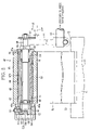
A packing machine of FIG. 1 is provided with a hopper device 10. The hopper device 10 has three hoppers 10 a, 10 b and 10 c, and a large number of filter cigarettes are stored in the hoppers. The hoppers 10 a, 10 b and 10 c are arranged adjacently to each other in a transferring direction of accumulation pockets 11. Each of the accumulation pockets 11, when passing through one hopper, receives a given number of filter cigarettes from the hopper. Consequently, when the accumulation pocket 11 passes through all the three hoppers, a cigarette bundle in a block-like shape is accommodated in the accumulation pocket 11. The cigarette bundle includes twenty filter cigarettes. In the accumulation pocket 11, the filter cigarettes are arranged in the form of upper, middle, and lower tiers. More specifically, the upper and lower tiers each include seven filter cigarettes, and the middle tier has six.
Thereafter, the accumulation pocket 11 is transferred along a transfer line to a first wheel 12 shown by a single dashed line. The first wheel 12, while rotating, receives a cigarette bundle from the accumulation pocket 11 and transfers the received cigarette bundle toward a second wheel 13 shown by a single dashed line. The first and second wheels 12 and 13 are disposed in a vertical position.
The second wheel 13 has a plurality of folding pockets 14. The folding pockets 14 are arranged at regular intervals in a circumferential direction of the second wheel 13. As the second wheel 13 rotates, each of the folding pockets 14 receives a cigarette bundle from the first wheel 12 and receives a sheet-like inner wrapper IW at the same time. The inner wrapper IW is then wound around the cigarette bundle into the shape of the letter U within the corresponding folding pocket 14.
The inner wrapper IW is fed from an inner wrapper feeder 15 to between the first and second wheels 12 and 13. The inner wrapper feeder 15 is provided with a vertical rotary turret 16. The rotary turret 16 has two bobbins 17 and 18. The bobbins 17 and 18 are disposed away from each other in a diametral direction of the rotary turret 16. Web rolls R1 and R2 are attached to the bobbins 17 and 18, respectively.
Each of the web rolls R includes a circular core and a web W wound around the core. The web W has aluminum foil forming the outside face of the web W, a paper layer laminated onto the aluminum foil and forming the inner side face of the web W, and an aromatic substance, for example menthol, applied to and infiltrated into the paper layer.
The rotary turret 16 is provided with scratching devices 19 and 20 near the web rolls R1 and R2, respectively. The scratching devices 19 and 20 will be described below in detail.
When the inner wrapper feeder 15 is in a state shown in FIG. 1, the web W1 delivered from the web roll R1 is guided along a feeding path PW. The feeding path PW extends toward the first and second wheels 12 and 13, and has a terminal end in a region between the wheels 12 and 13.
In the feeding path PW an automatic splicing unit 21 is arranged. The web W1 delivered from the web roll R1 passes through the automatic splicing unit 21, a sub feed unit 80, a web reservoir 22, a traveling guide 24, an embossing unit 25 and a main feed unit 28 in order. The sub and main feed units 80 and 28 cause the web W1 to run in cooperation with each other.
The web W2 of the web roll R2 is drawn out to reach the automatic splicing unit 21. In this case, the web roll R1 is used as an active roll, while the web roll R2 is a standby roll.
In cooperation with the sub feed unit 80 and the web reservoir 22, the automatic splicing unit 21 switches the active roll from the roll R1 to the roll R2. More specifically, when a remaining amount of the web W1 of the web roll R1 becomes equal to or less than a given amount, the sub feed unit 80 is activated at faster speed than the main feed unit 28. For this reason, the web reservoir 22 stores the web W1 of a given length therein by using a plurality of dancer rollers 23. Thereafter, the delivery of the web W1 from the web roll R1, which is carried out by the sub feed unit 80, is stopped. In this state, the automatic splicing unit 21 connects a distal end of the web W2 to the web W1, and then cuts the web W1 upstream from a position where the webs are spliced to each other. Subsequently, the automatic splicing unit 21 activates the sub feed unit 80 again, thereby switching the delivery of the web W from the roll R1 to the roll R2.
During the splicing work of the webs, the web W1 stored in the web reservoir 22 continues to be fed toward the embossing unit 25. This enables continuous feeding of the web W, and tension of the web W is retained at a fixed degree because of the dancer rollers 23 of the web reservoir 22.
The embossing unit 25 includes an internal path for the web W, which is formed by a plurality of guide rollers 26, and a pair of emboss rollers 27 inserted in the internal path. When the web W passes between the emboss rollers 27, the emboss rollers 27 form embosses with a given pattern in the web W.
The web W that has been embossed is fed from the embossing unit 25 through the main feed unit 28 to a cutting unit 29. The cutting unit 29 then cuts the web W into pieces with a given length, thereby forming the inner wrappers IW from the web W. Subsequently, the inner wrappers IW are sequentially fed through suction feed belts 30 and an acceleration roller unit 31 to the terminal end of the feeding path PW, and are pushed into the folding pockets 14 of the second wheel 13 together with cigarette bundles as described above.
The second wheel 13 is rotated, the cigarette bundle in the corresponding folding packet 14 is transferred in the circumferential direction of the second wheel 13. In this transferring process, the folding of an end flap for closing the end face of the cigarette bundle and the folding of side flaps for closing both side faces of the cigarette bundle are carried out in order as is publicly known with respect to the inner wrapper IW wound around the cigarette bundle, to thereby form an inner pack IP.
As illustrated in FIG. 1, a third wheel 33 adjoins the second wheel 13. The third wheel 33 is disposed away from the first wheel 12 in a diametral direction of the second wheel 13. The third wheel 33 has a plurality of transfer pockets (not shown). The transfer pockets sequentially receive their respective inner packs IP from the second wheel 13 while the third wheel rotates. Subsequently, the inner packs IP are transferred in a circumferential direction of the third wheel 33 together with the transfer pockets.
A fourth wheel 34 adjoins the third wheel 33. The fourth wheel 34 is disposed in a horizontal position in the same manner as the third wheel 33. More specifically, the fourth wheel 34 is located under the third wheel 33. Outer circumferences of the third and fourth wheels 33 and 34 partially overlap with each other in a vertical direction. The inner pack IP on the third wheel 33, when reaching the fourth wheel 34, is transferred from the third wheel 33 into a transfer pocket of the fourth wheel 34. The inner pack IP is then transferred in a circumferential direction of the fourth wheel 34 while the fourth wheel 34 rotates.
The fourth wheel 34 is connected to a sub blank feeder 35. The sub blank feeder 35 feeds a sub blank to a transfer pocket of the fourth wheel 34 before the transfer pocket receives the inner pack IP.
More specifically, the sub blank feeder 35 is provided with a web roll RS. The blank roll RS delivers a web WS along a feeding path PSB. In the feeding path PSB, a notch/cutter roller, a feed unit and a cutting unit are arranged in order from the roll RS side although none of them is shown in FIG. 1. The feed unit intermittently feeds the web WS. In this feeding process, the notch/cutter roller forms a pair of side fold lines and the like in the web WS, and the cutting unit cuts the web WS into pieces with a given length, to thereby form a sub blank.
When a transfer pocket of the fourth wheel 34 reaches the third wheel 33 after receiving a sub blank, an inner pack IP of the third wheel 33 is pushed into the transfer pocket together with the sub blank. At this moment, the sub blank is folded along the side fold lines to form an inner frame. The inner frame is bonded to the inner pack IP. Subsequently, the inner pack IP provided with the inner frame is transferred while the fourth wheel 34 rotates.
Further connected to the fourth wheel 34 is a main blank feeder 36. The main blank feeder 36 feeds a main blank (outer wrapper) to the inner pack IP on the fourth wheel 34. As illustrated in FIG. 1, the main blank feeder 36 has a hopper 37 storing main blanks. The main blanks are transferred one by one from the hopper 37 through a feeding path PMB to the fourth wheel 34, and are fed to the respective inner packs IP at a feeding position of the fourth wheel 34. More specifically, each of the main blanks is placed on the corresponding inner pack IP so as to sandwich the inner pack IP in cooperation with the inner frame.
A fifth wheel 38 is disposed in a vertical position right above the feeding position of the fourth wheel 34. The fifth wheel 38 has a plurality of folding pockets (not shown). While the fifth wheel 38 rotates, each of the folding pockets receives the corresponding inner pack IP having the inner frame and the main blank from the fourth wheel 34. At this point, a pair of inner side flaps of the main blank is folded. The received inner pack IP is then transferred in a circumferential direction of the fifth wheel 38. In this transferring process, the rest of the folding process with respect to the main blank is carried out in order, to thereby form a cigarette package SP.
Thereafter, the cigarette package SP is transferred from the fifth wheel 38 through a sixth wheel 39, a seventh wheel 40 and an eighth wheel 41 to a delivery line 42. The delivery line 42 feeds the cigarette package SP to a film-wrapping machine. The film-wrapping machine wraps the cigarette package in a film sheet.
The scratching devices 19 and 20 will be described below. As the scratching devices 19 and 20 have identical structures, the following description will be only about the scratching device 19 to avoid repeating a similar description.
As illustrated in FIG. 2, the scratching device 19 has a support shaft 43. The support shaft 43 horizontally extends from the rotary turret 16 of the inner wrapper feeder 15 and includes a distal end. Rotatably mounted on the distal end of the support shaft 43 is an arm 44 or a proximal end thereof. The arm 44 extends toward the web roll R1.
A return coil spring (not shown) is disposed between the proximal end of the arm 44 and the support shaft 43, and a scraper roller 45 is fixed to a distal end of the arm 44. The return coil spring urges the scraper roller 45 toward the web roll R1 using the arm 44. This presses the scraper roller 45 against an outer circumferential surface of the web roll R1.
More specifically, the scraper roller 45 has a roller shaft 46. The roller shaft 46 extends parallel with an axis of the web roll R1. A distal end of the roller shaft 46 is unrotatably supported by the distal p end of the arm 44.
A sleeve 47 is concentrically disposed outside the roller shaft 46. The sleeve 47 extends in an axial direction of the roller shaft 46 and has a flange 47 a at one end on the arm 44 side. There is formed a circumferential groove 47 b in the middle of an outer circumferential surface of the sleeve 47 as viewed in the axial direction of the sleeve 47.
A pair of bearings 60 is disposed in one end portion of the sleeve 47. The bearings 60 are disposed away from each other in the axial direction of the sleeve 47 and support the one end portion of the sleeve 47 so as to be rotatable with respect to the roller shaft 46. A bearing 49 is disposed in the other end portion of the sleeve 47. The bearing 49 supports the other end portion of the sleeve 47 so as to be rotatable with respect to the roller shaft 46.
Disposed between the one end portion of the sleeve 47 and the roller shaft 46 is a one-way clutch 50. The one-way clutch 50 is sandwiched between the bearings 60. The one-way clutch 50 allows the sleeve 47 to rotate only in one direction in relation to a circumferential direction of the roller shaft 46.
Disposed in the outer circumferential surface of the sleeve 47 is a roller shell 48 formed into a hollow cylinder. The roller shell 48 extends from the one end portion of the sleeve 47 to the other end portion thereof to cover the circumferential groove 47 b of the sleeve 47. The roller shell 48 has one end in contact with the flange 47 a of the sleeve 47 and a flange 48 a formed in the other end thereof.
An axial groove 62 is formed in an inner circumferential surface of the one end in the roller shell 48. The axial groove 62 opens in one end face of the roller shell 48. A pin 51 is protruding from an outer circumferential surface of a distal end portion in the sleeve 47. The pin 51 is fitted into the axial groove 62. The axial groove 62 and the pin 51 are engaged with each other to cause the roller shell 48 and the sleeve 47 to rotate integrally. However, the axial groove 62 and the pin 51 allow the sleeve 47 to move in the axial direction of the roller shell 48 toward the distal end side of the roller shaft 46. Accordingly, the roller shell 48 can be pulled out from the sleeve 47 toward the distal end side of the roller shaft 46.
As is apparent from FIG. 2, the distal end portion of the sleeve 47 is protruding from the other end or the flange 48 a of the roller shell 48. Fixed to the distal end of the sleeve 47 is a ring-shaped stopper 52. The stopper 52 is in contact with the flange 48 a of the roller shell 48, to thereby prevent the roller shell 48 from dropping out of the sleeve 47.
More specifically, the stopper 52 has a plurality of stopper bolts 53. The stopper bolts 53 are arranged away from each other in a circumferential direction of the stopper 52. Each of the stopper bolts 53 is screwed into the stopper 52, and has an inner end inserted into the sleeve 47. In other words, a plurality of axial grooves 64 corresponding to the stopper bolts 53 are formed in the distal end portion of the sleeve 47. The axial grooves 64 open in the distal end face of the sleeve 47. Therefore, the stopper bolts 53 are allowed to enter the sleeve 47 through the axial grooves 64. Balls 66 are hold in the distal ends of the respective stopper bolts 53. The balls 66 are fitted in a circumferential groove 68 of the sleeve 47. The circumferential groove 68 is formed in the outer circumferential surface of the distal end portion of the sleeve 47.
As illustrated in FIG. 3, a plurality of mounting grooves 70 are formed in an outer circumferential surface of the roller shell 48. The mounting grooves 70 extend in the axial direction of the roller shell 48, and are arranged at regular intervals in a circumferential direction of the roller shell 48. Scrapers 55 are fitted into the respective mounting grooves 70. The scrapers 55 are made, for example, of felt material, and each have a substantially rectangular cross section. The scrapers 55 are protruding from the outer circumferential surface of the roller shell 48 and extend between the flange 47 a of the sleeve 47 and the flange 48 a of the roller shell 48 along the mounting grooves 70. Therefore, the scraper roller 45 has a plurality of concavities 56 arranged in the circumferential direction of the roller shell 48. Each of the concavities 56 is defined between two adjacent scrapers 55.
As illustrated in FIG. 2, a detection disc 57 is eccentrically mounted on the proximal end of the roller shaft 46. The detection disc 57 is located adjacently to the distal end of the arm 44. When the scraper roller 45, or the scraper 55, is in contact with the outer circumferential surface of the web roll R1, there is secured a given distance D between a horizontal plane HP including the end face of the scrapers 55 and the detection disc 55. The bobbin 17 of the web roll R1 has flanges 72 disposed in both ends thereof. The flange 72 on the rotary turret 16 side and the detection disc 57 are located in the same vertical plane. In FIG. 2, reference character C denotes the core of the web roll R1.
Operation of the above-mentioned scratching device 19 will be described below.
As stated, when the web W is delivered from the web roll R1, at least one of the scrapers 55 of the scraper roller 45 is pressed against the outer circumferential surface of the web roll R1 as illustrated in FIG. 4.
When the web roll R1 is rotated in a direction of an arrow in FIG. 4, that is, counterclockwise while the web W is delivered, the scraper roller 45 receives a clockwise rotating force from the web roll R1. However, the one-way clutch 50 of the scraper roller 45 inhibits the rotation of the scraper roller 45. As a result, the scraper 55 is kept in a state pressed against the outer circumferential surface of the web roll R1, namely an outside face of the web W, and the web W is delivered from the web roll R1 while the outside face thereof slides against the scraper 55.
As mentioned, the web roll R1 is formed by winding the web W around the core C, and the paper layer of the web W is infiltrated with menthol. Therefore, when the web W is in the form of the web roll R, the menthol is transferred from the paper layer to the outside face of the adjoining web W, that is, the aluminum foil, so that menthol M adheres onto the outside face S of the web W as illustrated in FIG. 5.
When the web W is delivered from the web roll R1, however, the outside face S of the web W is brought into sliding contact with the scraper 55, so that the menthol M that has adhered onto the front face S is scraped by the scraper 55 and removed or cleaned from the outside face S. Since the scraper 55 is made of felt material, the scraper 55 can scrape the menthol M off the outside face S reliably and effectively without damaging the outside face S. The scraped menthol M is trapped and accumulated in the concavity 56 of the scraper roller 45. Consequently, the menthol M does not spatter around the scraper roller 45, and then does not stain the periphery of the scraper roller 45.
When the web W is delivered from the web roll R1, the menthol M on the outside face of the web W is immediately removed or cleaned by the scraper 55 as described above. Therefore, in the feeding path PW, the adhesion of the menthol to a large number of the guides brought into contact with the outside face S of the web W, that is, smudges on the feeding path PW caused by adhesion of the menthol, are reduced. This prevents the web W from slipping, meandering, jamming and the like in the feeding path PW, thereby cutting the web W by the cutting unit 29 with accuracy. As a result, it is possible not only to obtain the inner wrapper IW of regulation size but also to accurately position the inner wrapper IW in the feeding position between the first wheel 12 and the second wheel 14, to thereby wrap the cigarette bundle in the inner wrapper IW satisfactorily.
As the web W is continuously delivered from the web roll R1, a diameter of the web roll R1 is reduced. In other words, as illustrated in FIG. 4, an external diameter of the web roll R1 is reduced from a maximum external diameter DMAX (solid line) to an intermediate external diameter D1 (double dashed line) to a minimum external diameter DMIN (single dashed line) indicative of a use limit of the web roll R1.
When the external diameter of the web roll R1 reaches the minimum external diameter DMIN, that is to say, when the outside face S of the web roll R1 reaches further inside than the outer circumferential surface of the flange 72 of the bobbin 17 in a radial direction of the bobbin 17 as is obvious from FIG. 4, the eccentric disc 57 is brought into contact to the outer circumferential surface of the flange 72. At this point, a detection sensor (not shown) for detecting a remaining amount of the web W in the web roll R1 is turned ON. As a detection sensor, a sensor for detecting electric conduction and mechanical contact between the eccentric disc 57 and the flange 72 may be utilized.
Once the detection sensor is turned ON, the operation of the automatic splicing unit 21 is started. The automatic splicing unit 21 switches the delivery of the web W from the web roll R1 to the web roll R2.
When the web W is delivered from the web roll R2, a scraper of the scratching device 20 remove or clean the menthol that has adhered onto the outside face S of the web W in the same manner as the scraper 55 of the scratching device 19.
Subsequently, the rotary turret 16 is rotated counter clockwise to make approximately a half rotation, in view of FIG. 1. The web roll R1 of the bobbin 17 is moved to the standby position, and the web roll R2 of the bobbin 18 to the active position.
In the above-described state, the web roll R1 of the bobbin 17 is replaced with a new web roll, which will serve as a standby roll. At this point, the scraper roller 45 of the scratching device 19 is manually rotated at a given angle in a direction allowed by the one-way clutch 50. Due to this rotation, a new scraper 55 of the scraper 45 is pressed against the outer circumferential surface of the standby roll. Accordingly, each time the web roll R is replaced, a new scraper 55 is pressed against the outside face of the web W of the standby roll.
When all the scrapers 55 of the scraper 45 are used, the stopper 52 is detached from the sleeve 47, and the roller shell 48 is pulled out from the sleeve 47 with the scrapers 55. Thereafter, the roller shell 48 having new scrapers is fixed to the sleeve 47.
The detached roller shell 48 can be reused after the menthol M in the concavities 56 is removed.
In general, the remaining amount of the web roll, namely the minimum external diameter DMIN of the web roll, is detected by the angle of the arm 44 in the scratching device. However, the scraper 55 of the scraper roller 45 is liable to deform, so that it is not proper that the remaining amount of the web roll is detected on the basis of the angle of the arm 44.

Claims (6)

1. A feeding apparatus for feeding an inner wrapper for wrapping a cigarette bundle, comprising:
a web roll rotatably supported and wound with a web that is material for the inner wrapper, the web including metal foil, and a paper layer that is laminated on the metal foil and contains an aromatic substance;
a feeding path for guiding the web delivered from said web roll to a feeding position;
a cutting unit arranged in said feeding path, for cutting the web to form the inner wrapper;
a cleaner arranged in said feeding path including said web roll, for cleaning a surface of the metal foil of the web; and
a holder fastened to a distal end of the arm and having the scraper,
wherein said cleaner includes an arm having a proximal end rotatably supported near said web roll, the arm being urged toward the outer circumferential surface of said web roll,
wherein the holder is rotatable with respect to the arm and has a plurality of scrapers, and wherein the holder is a scraper roller including:
a roller shaft supported by the arm,
a sleeve rotatably supported by the roller shaft,
a one-way clutch disposed between the sleeve and the roller shaft, for allowing the sleeve to only rotate in the same direction as a rotating direction of said web roll, and
a roller shell detachably fixed onto the sleeve, and the scrapers is arranged in an outer circumferential surface of the roller shell at intervals in a circumferential direction of the roller shell.
2. The feeding apparatus according to claim 1, wherein:
the aromatic substance is menthol.
3. The feeding apparatus according to claim 2, wherein:
said cleaner includes a scraper brought into sliding contact with the surface of the metal foil at an outer circumferential surface of said web roll.
4. The feeding apparatus according to claim 1, wherein:
the scrapers are made of felt material.
5. The feeding apparatus according to claim 4, further including a detector for detecting whether or not a diameter of said web roll reaches a minimum diameter that determines a use limit of said web roll.
6. The feeding apparatus according to claim 5, wherein:
the detector includes:
a bobbin for supporting said web roll and having a flange; and
a contact member fixed to the scraper roller, the contact member being brought into contact with the flange of the bobbin when the diameter of said web roll reaches the minimum diameter.
US11/328,241 2003-07-16 2006-01-10 Apparatus for feeding inner wrapper for wrapping cigarette bundles Active US7325368B2 (en)

Applications Claiming Priority (3)

Application Number Priority Date Filing Date Title
JP2003-275478 2003-07-16
JP2003275478 2003-07-16
PCT/JP2004/010133 WO2005007512A1 (en) 2003-07-16 2004-07-15 Apparatus for supplying inner packaging material for packaging cigarette bundle

Related Parent Applications (1)

Application Number Title Priority Date Filing Date
PCT/JP2004/010133 Continuation WO2005007512A1 (en) 2003-07-16 2004-07-15 Apparatus for supplying inner packaging material for packaging cigarette bundle

Publications (2)

Publication Number Publication Date
US20060168909A1 US20060168909A1 (en) 2006-08-03
US7325368B2 true US7325368B2 (en) 2008-02-05

Family

ID=34074558

Family Applications (1)

Application Number Title Priority Date Filing Date
US11/328,241 Active US7325368B2 (en) 2003-07-16 2006-01-10 Apparatus for feeding inner wrapper for wrapping cigarette bundles

Country Status (10)

Country Link
US (1) US7325368B2 (en)
EP (1) EP1645511B1 (en)
JP (1) JP4375753B2 (en)
CN (1) CN100413760C (en)
AT (1) ATE445536T1 (en)
CA (1) CA2531804C (en)
DE (1) DE602004023610D1 (en)
RU (1) RU2314977C2 (en)
UA (1) UA87987C2 (en)
WO (1) WO2005007512A1 (en)

Cited By (4)

* Cited by examiner, † Cited by third party
Publication number Priority date Publication date Assignee Title
US20080047226A1 (en) * 2006-08-03 2008-02-28 G.D Societa'per Azioni Cigarette Packing Machine for Producing Rigid, Hinged-Lid Packets
US20110146210A1 (en) * 2009-12-21 2011-06-23 Michels Frank Rolf Method of and apparatus for wrapping a stack of objects with a film
US20140311096A1 (en) * 2011-09-29 2014-10-23 Focke & Co. (Gmbh & Co. Kg) Method and device for producing a package for a group of smokable articles
WO2015138456A1 (en) 2014-03-12 2015-09-17 R. J. Reynolds Tobacco Company Smoking article package inspection system and associated method

Families Citing this family (9)

* Cited by examiner, † Cited by third party
Publication number Priority date Publication date Assignee Title
US20080099353A1 (en) * 2006-10-31 2008-05-01 Heather Noelle Parsons Cigarette package
US20080230410A1 (en) * 2007-03-22 2008-09-25 Wesley Steven Jones Cigarette package
US7762046B2 (en) * 2008-04-11 2010-07-27 R.J. Reynolds Tobacco Company Method for manufacturing cigarette packages
DE102008047773A1 (en) * 2008-09-17 2010-04-15 Focke & Co.(Gmbh & Co. Kg) Pack of cigarettes and method and apparatus for making same
US8046978B2 (en) * 2009-10-02 2011-11-01 R.J. Reynolds Tobacco Company Equipment and method for packaging multiple packets of cigarettes
CN103043239A (en) * 2012-12-28 2013-04-17 广东中烟工业有限责任公司 Cigarette aluminum foil folding machine with cleaning device
EP3412159A1 (en) * 2017-06-09 2018-12-12 Philip Morris Products S.a.s. Tobacco flavouring mat and related container
CN109455324A (en) * 2018-12-27 2019-03-12 浙江旭翔机械科技有限公司 Wrapping paper bactericidal device for bottle placer
CN113524862B (en) * 2021-06-22 2022-11-04 创越新材料(泰州)有限公司 Semi-flexible plate compounding device and process

Citations (17)

* Cited by examiner, † Cited by third party
Publication number Priority date Publication date Assignee Title
US3416289A (en) * 1965-07-19 1968-12-17 Hauni Werke Koerber & Co Kg Apparatus for wrapping cigarette packs and the like
US3432982A (en) * 1964-09-21 1969-03-18 Windmoeller & Hoelscher Method and apparatus for applying closure heat-seals to filled plastic bags
US3815313A (en) * 1972-10-04 1974-06-11 R Heisler Apparatus and method for automatically sizing and wrapping a shrink wrap envelope around advancing luggage
US3848393A (en) * 1971-02-04 1974-11-19 Monaghan Automated Syst Inc Packaging machine and process
US3884012A (en) * 1972-08-11 1975-05-20 Tetra Pak Dev Method and apparatus for the packing under aseptic conditions of sterile goods into containers
US3906893A (en) 1972-07-12 1975-09-23 Imp Group Ltd Impregnation of a travelling web
JPS5823781A (en) 1981-07-28 1983-02-12 サシブ・ソチエタ・ペル・アツイオ−ニ Apparatus for detecting outer diameter of web roll
US4573305A (en) * 1984-07-30 1986-03-04 Bemis Company, Inc. Unit load wrapping with uniform wrap tension along the periphery of the wrapped load
JPH04279415A (en) 1990-08-15 1992-10-05 Philip Morris Prod Inc Method for flattening exposed foil at top of cigarette bundle to eliminate clear fold
US5197938A (en) * 1991-10-31 1993-03-30 International Stripping & Die Cutting Corp. Waste remover for die cut blanks
US5822951A (en) * 1997-11-06 1998-10-20 Modern Controls, Inc. Apparatus and method for sampling gas in product packages
JP2000006929A (en) 1998-06-09 2000-01-11 Focke & Co Gmbh & Co Packaging machine for cigarette in particular
JP2000118510A (en) 1998-10-19 2000-04-25 Japan Tobacco Inc Inner wrapping material feeder for tobacco packaging machine
WO2002026563A1 (en) 2000-09-27 2002-04-04 Japan Tobacco Inc. Packaging material folding device of packaging machine
JP2002193356A (en) 2000-12-28 2002-07-10 Haruno International Kk Cigarette packaging box
US6449925B1 (en) * 1996-11-29 2002-09-17 Kabushiki Kaisha Hayashibara Seibutsu Kagaku Kenkyujo Method for preparing inclusion packaged product
US6769226B2 (en) * 1997-03-20 2004-08-03 Cardinal Health 409, Inc. Gelatin encapsulation techniques

Family Cites Families (4)

* Cited by examiner, † Cited by third party
Publication number Priority date Publication date Assignee Title
DE1983430U (en) * 1967-12-19 1968-04-11 Alfred Gutmann Ges Fuer Maschb DEVICE FOR CLEARING ABRASIVE AGENT DEPOSITED ON BLASTED WORKPIECES.
DE19721144B4 (en) * 1997-05-21 2006-04-20 Focke & Co.(Gmbh & Co. Kg) Method and device for handling blanks
IT1295642B1 (en) * 1997-10-23 1999-05-24 Gd Spa METHOD AND UNIT FOR FEEDING A CONTINUOUS BELT OF PRE-IMPREGNATED WRAPPING MATERIAL INTO A PRODUCT WRAPPING MACHINE
DE19851775A1 (en) * 1998-11-10 2000-05-11 Focke & Co Packaging machine for cigarettes

Patent Citations (18)

* Cited by examiner, † Cited by third party
Publication number Priority date Publication date Assignee Title
US3432982A (en) * 1964-09-21 1969-03-18 Windmoeller & Hoelscher Method and apparatus for applying closure heat-seals to filled plastic bags
US3416289A (en) * 1965-07-19 1968-12-17 Hauni Werke Koerber & Co Kg Apparatus for wrapping cigarette packs and the like
US3848393A (en) * 1971-02-04 1974-11-19 Monaghan Automated Syst Inc Packaging machine and process
US3906893A (en) 1972-07-12 1975-09-23 Imp Group Ltd Impregnation of a travelling web
US3884012A (en) * 1972-08-11 1975-05-20 Tetra Pak Dev Method and apparatus for the packing under aseptic conditions of sterile goods into containers
US3815313A (en) * 1972-10-04 1974-06-11 R Heisler Apparatus and method for automatically sizing and wrapping a shrink wrap envelope around advancing luggage
JPS5823781A (en) 1981-07-28 1983-02-12 サシブ・ソチエタ・ペル・アツイオ−ニ Apparatus for detecting outer diameter of web roll
US4573305A (en) * 1984-07-30 1986-03-04 Bemis Company, Inc. Unit load wrapping with uniform wrap tension along the periphery of the wrapped load
JPH04279415A (en) 1990-08-15 1992-10-05 Philip Morris Prod Inc Method for flattening exposed foil at top of cigarette bundle to eliminate clear fold
US5197938A (en) * 1991-10-31 1993-03-30 International Stripping & Die Cutting Corp. Waste remover for die cut blanks
US6449925B1 (en) * 1996-11-29 2002-09-17 Kabushiki Kaisha Hayashibara Seibutsu Kagaku Kenkyujo Method for preparing inclusion packaged product
US6769226B2 (en) * 1997-03-20 2004-08-03 Cardinal Health 409, Inc. Gelatin encapsulation techniques
US5822951A (en) * 1997-11-06 1998-10-20 Modern Controls, Inc. Apparatus and method for sampling gas in product packages
JP2000006929A (en) 1998-06-09 2000-01-11 Focke & Co Gmbh & Co Packaging machine for cigarette in particular
US6357201B1 (en) * 1998-06-09 2002-03-19 Focke & Co. (Gmbh & Co.) Packaging machine, in particular for cigarettes
JP2000118510A (en) 1998-10-19 2000-04-25 Japan Tobacco Inc Inner wrapping material feeder for tobacco packaging machine
WO2002026563A1 (en) 2000-09-27 2002-04-04 Japan Tobacco Inc. Packaging material folding device of packaging machine
JP2002193356A (en) 2000-12-28 2002-07-10 Haruno International Kk Cigarette packaging box

Cited By (6)

* Cited by examiner, † Cited by third party
Publication number Priority date Publication date Assignee Title
US20080047226A1 (en) * 2006-08-03 2008-02-28 G.D Societa'per Azioni Cigarette Packing Machine for Producing Rigid, Hinged-Lid Packets
US20110146210A1 (en) * 2009-12-21 2011-06-23 Michels Frank Rolf Method of and apparatus for wrapping a stack of objects with a film
US9440756B2 (en) * 2009-12-21 2016-09-13 Msk-Verpackungs-Systeme Gmbh Method of and apparatus for wrapping a stack of objects with a film
US20140311096A1 (en) * 2011-09-29 2014-10-23 Focke & Co. (Gmbh & Co. Kg) Method and device for producing a package for a group of smokable articles
US9988164B2 (en) * 2011-09-29 2018-06-05 Focke & Co. (Gmbh & Co. Kg) Method and device for producing a package for a group of smokable articles
WO2015138456A1 (en) 2014-03-12 2015-09-17 R. J. Reynolds Tobacco Company Smoking article package inspection system and associated method

Also Published As

Publication number Publication date
CN100413760C (en) 2008-08-27
UA87987C2 (en) 2009-09-10
EP1645511A4 (en) 2008-01-02
CA2531804C (en) 2009-09-15
CN1822986A (en) 2006-08-23
US20060168909A1 (en) 2006-08-03
EP1645511B1 (en) 2009-10-14
JPWO2005007512A1 (en) 2006-11-16
WO2005007512A1 (en) 2005-01-27
RU2314977C2 (en) 2008-01-20
DE602004023610D1 (en) 2009-11-26
JP4375753B2 (en) 2009-12-02
CA2531804A1 (en) 2005-01-27
EP1645511A1 (en) 2006-04-12
ATE445536T1 (en) 2009-10-15
RU2006104711A (en) 2006-06-27

Similar Documents

Publication Publication Date Title
US7325368B2 (en) Apparatus for feeding inner wrapper for wrapping cigarette bundles
CA2560661C (en) Ream wrap and packaging materials with tear tapes and tear tape applicator for same
KR100624260B1 (en) Device for gluing rolls of web material and associated method
FR2514334A1 (en) DEVICE FOR ACCUMULATING FLAT PRODUCTS, ESPECIALLY PRINTING PRODUCTS, ARRIVING IN A MUTUAL OVERLAPPING RELATIONSHIP
JP2010143222A (en) Apparatus for printing sheet strip
JP3411082B2 (en) Glue transfer device for chip paper
JPH0651543B2 (en) Equipment for rewinding paper
EP2616242B1 (en) Device for guiding strips for a stamping machine
EP1599386B1 (en) Process and apparatus for folding and applying onserts onto consumer goods
JPH07112753B2 (en) Method and apparatus for making a self-adhesive sticky note block
JP2654771B2 (en) Method for storing printed matter and winding unit used for carrying out the method
FR2528023A1 (en) PROCESS AND DEVICE FOR THE RECOVERY OF FLAT PRODUCTS PRESENTING IN SCALE PROVISIONS, PARTICULARLY FOR THE RECOVERY OF PRINTED SHEETS
GB2260532A (en) A device for splicing strips of limited transverse dimensions automatically
US3782665A (en) Winding of continuous webs of sheet material
CN103387061A (en) Film cassette
JP2005507252A (en) A device for coating a group of filter segments with a coating material and a multi-segment filter manufacturing device to manufacture multi-segment filters in the tobacco processing industry
US6095959A (en) Method and unit for feeding, in a product wrapping machine, a continuous band of wrapping material, the surface of which is pre-impregnated with an aromatizing substance
JP2006008253A (en) Method and unit for folding coupon ticket on packaging machine
US20020056257A1 (en) Method of and apparatus for making and manipulating coupons in cigarette packing machines
US6422282B1 (en) Apparatus for treating webs prior to splicing
US6044619A (en) Reel slitting device and method
JPH09122550A (en) Glue applying device for wrapping paper
US6936305B1 (en) Method and equipment for producing rolls of moistened web material
FI92031C (en) Arrangement in a wrapper feeder
US8528303B2 (en) Equipment for feeding strip material in packaging machines

Legal Events

Date Code Title Description
AS Assignment

Owner name: JAPAN TOBACCO INC., JAPAN

Free format text: ASSIGNMENT OF ASSIGNORS INTEREST;ASSIGNORS:MIYAOKA, NORIKUNI;HYODO, SHINICHI;REEL/FRAME:017472/0029

Effective date: 20060320

STCF Information on status: patent grant

Free format text: PATENTED CASE

FEPP Fee payment procedure

Free format text: PAYOR NUMBER ASSIGNED (ORIGINAL EVENT CODE: ASPN); ENTITY STATUS OF PATENT OWNER: LARGE ENTITY

FPAY Fee payment

Year of fee payment: 4

FEPP Fee payment procedure

Free format text: PAYER NUMBER DE-ASSIGNED (ORIGINAL EVENT CODE: RMPN); ENTITY STATUS OF PATENT OWNER: LARGE ENTITY

Free format text: PAYOR NUMBER ASSIGNED (ORIGINAL EVENT CODE: ASPN); ENTITY STATUS OF PATENT OWNER: LARGE ENTITY

FPAY Fee payment

Year of fee payment: 8

MAFP Maintenance fee payment

Free format text: PAYMENT OF MAINTENANCE FEE, 12TH YEAR, LARGE ENTITY (ORIGINAL EVENT CODE: M1553); ENTITY STATUS OF PATENT OWNER: LARGE ENTITY

Year of fee payment: 12