US7321800B2 - Control system and method of controlling an injection molding machine - Google Patents
Control system and method of controlling an injection molding machine Download PDFInfo
- Publication number
- US7321800B2 US7321800B2 US11/293,339 US29333905A US7321800B2 US 7321800 B2 US7321800 B2 US 7321800B2 US 29333905 A US29333905 A US 29333905A US 7321800 B2 US7321800 B2 US 7321800B2
- Authority
- US
- United States
- Prior art keywords
- control unit
- control system
- central control
- additional
- injection molding
- Prior art date
- Legal status (The legal status is an assumption and is not a legal conclusion. Google has not performed a legal analysis and makes no representation as to the accuracy of the status listed.)
- Expired - Fee Related
Links
Images


Classifications
-
- B—PERFORMING OPERATIONS; TRANSPORTING
- B29—WORKING OF PLASTICS; WORKING OF SUBSTANCES IN A PLASTIC STATE IN GENERAL
- B29C—SHAPING OR JOINING OF PLASTICS; SHAPING OF MATERIAL IN A PLASTIC STATE, NOT OTHERWISE PROVIDED FOR; AFTER-TREATMENT OF THE SHAPED PRODUCTS, e.g. REPAIRING
- B29C45/00—Injection moulding, i.e. forcing the required volume of moulding material through a nozzle into a closed mould; Apparatus therefor
- B29C45/17—Component parts, details or accessories; Auxiliary operations
- B29C45/76—Measuring, controlling or regulating
-
- B—PERFORMING OPERATIONS; TRANSPORTING
- B29—WORKING OF PLASTICS; WORKING OF SUBSTANCES IN A PLASTIC STATE IN GENERAL
- B29C—SHAPING OR JOINING OF PLASTICS; SHAPING OF MATERIAL IN A PLASTIC STATE, NOT OTHERWISE PROVIDED FOR; AFTER-TREATMENT OF THE SHAPED PRODUCTS, e.g. REPAIRING
- B29C2945/00—Indexing scheme relating to injection moulding, i.e. forcing the required volume of moulding material through a nozzle into a closed mould
- B29C2945/76—Measuring, controlling or regulating
- B29C2945/76003—Measured parameter
- B29C2945/76066—Time
- B29C2945/76076—Time duration
-
- B—PERFORMING OPERATIONS; TRANSPORTING
- B29—WORKING OF PLASTICS; WORKING OF SUBSTANCES IN A PLASTIC STATE IN GENERAL
- B29C—SHAPING OR JOINING OF PLASTICS; SHAPING OF MATERIAL IN A PLASTIC STATE, NOT OTHERWISE PROVIDED FOR; AFTER-TREATMENT OF THE SHAPED PRODUCTS, e.g. REPAIRING
- B29C2945/00—Indexing scheme relating to injection moulding, i.e. forcing the required volume of moulding material through a nozzle into a closed mould
- B29C2945/76—Measuring, controlling or regulating
- B29C2945/76003—Measured parameter
- B29C2945/76083—Position
-
- B—PERFORMING OPERATIONS; TRANSPORTING
- B29—WORKING OF PLASTICS; WORKING OF SUBSTANCES IN A PLASTIC STATE IN GENERAL
- B29C—SHAPING OR JOINING OF PLASTICS; SHAPING OF MATERIAL IN A PLASTIC STATE, NOT OTHERWISE PROVIDED FOR; AFTER-TREATMENT OF THE SHAPED PRODUCTS, e.g. REPAIRING
- B29C2945/00—Indexing scheme relating to injection moulding, i.e. forcing the required volume of moulding material through a nozzle into a closed mould
- B29C2945/76—Measuring, controlling or regulating
- B29C2945/76003—Measured parameter
- B29C2945/7611—Velocity
-
- B—PERFORMING OPERATIONS; TRANSPORTING
- B29—WORKING OF PLASTICS; WORKING OF SUBSTANCES IN A PLASTIC STATE IN GENERAL
- B29C—SHAPING OR JOINING OF PLASTICS; SHAPING OF MATERIAL IN A PLASTIC STATE, NOT OTHERWISE PROVIDED FOR; AFTER-TREATMENT OF THE SHAPED PRODUCTS, e.g. REPAIRING
- B29C2945/00—Indexing scheme relating to injection moulding, i.e. forcing the required volume of moulding material through a nozzle into a closed mould
- B29C2945/76—Measuring, controlling or regulating
- B29C2945/76003—Measured parameter
- B29C2945/76163—Errors, malfunctioning
-
- B—PERFORMING OPERATIONS; TRANSPORTING
- B29—WORKING OF PLASTICS; WORKING OF SUBSTANCES IN A PLASTIC STATE IN GENERAL
- B29C—SHAPING OR JOINING OF PLASTICS; SHAPING OF MATERIAL IN A PLASTIC STATE, NOT OTHERWISE PROVIDED FOR; AFTER-TREATMENT OF THE SHAPED PRODUCTS, e.g. REPAIRING
- B29C2945/00—Indexing scheme relating to injection moulding, i.e. forcing the required volume of moulding material through a nozzle into a closed mould
- B29C2945/76—Measuring, controlling or regulating
- B29C2945/76177—Location of measurement
- B29C2945/7618—Injection unit
- B29C2945/76187—Injection unit screw
-
- B—PERFORMING OPERATIONS; TRANSPORTING
- B29—WORKING OF PLASTICS; WORKING OF SUBSTANCES IN A PLASTIC STATE IN GENERAL
- B29C—SHAPING OR JOINING OF PLASTICS; SHAPING OF MATERIAL IN A PLASTIC STATE, NOT OTHERWISE PROVIDED FOR; AFTER-TREATMENT OF THE SHAPED PRODUCTS, e.g. REPAIRING
- B29C2945/00—Indexing scheme relating to injection moulding, i.e. forcing the required volume of moulding material through a nozzle into a closed mould
- B29C2945/76—Measuring, controlling or regulating
- B29C2945/76177—Location of measurement
- B29C2945/76314—Auxiliary devices
- B29C2945/76321—Auxiliary devices conveyors
-
- B—PERFORMING OPERATIONS; TRANSPORTING
- B29—WORKING OF PLASTICS; WORKING OF SUBSTANCES IN A PLASTIC STATE IN GENERAL
- B29C—SHAPING OR JOINING OF PLASTICS; SHAPING OF MATERIAL IN A PLASTIC STATE, NOT OTHERWISE PROVIDED FOR; AFTER-TREATMENT OF THE SHAPED PRODUCTS, e.g. REPAIRING
- B29C2945/00—Indexing scheme relating to injection moulding, i.e. forcing the required volume of moulding material through a nozzle into a closed mould
- B29C2945/76—Measuring, controlling or regulating
- B29C2945/76451—Measurement means
- B29C2945/76461—Optical, e.g. laser
- B29C2945/76464—Optical, e.g. laser cameras
-
- B—PERFORMING OPERATIONS; TRANSPORTING
- B29—WORKING OF PLASTICS; WORKING OF SUBSTANCES IN A PLASTIC STATE IN GENERAL
- B29C—SHAPING OR JOINING OF PLASTICS; SHAPING OF MATERIAL IN A PLASTIC STATE, NOT OTHERWISE PROVIDED FOR; AFTER-TREATMENT OF THE SHAPED PRODUCTS, e.g. REPAIRING
- B29C2945/00—Indexing scheme relating to injection moulding, i.e. forcing the required volume of moulding material through a nozzle into a closed mould
- B29C2945/76—Measuring, controlling or regulating
- B29C2945/76494—Controlled parameter
- B29C2945/76498—Pressure
-
- B—PERFORMING OPERATIONS; TRANSPORTING
- B29—WORKING OF PLASTICS; WORKING OF SUBSTANCES IN A PLASTIC STATE IN GENERAL
- B29C—SHAPING OR JOINING OF PLASTICS; SHAPING OF MATERIAL IN A PLASTIC STATE, NOT OTHERWISE PROVIDED FOR; AFTER-TREATMENT OF THE SHAPED PRODUCTS, e.g. REPAIRING
- B29C2945/00—Indexing scheme relating to injection moulding, i.e. forcing the required volume of moulding material through a nozzle into a closed mould
- B29C2945/76—Measuring, controlling or regulating
- B29C2945/76494—Controlled parameter
- B29C2945/76531—Temperature
-
- B—PERFORMING OPERATIONS; TRANSPORTING
- B29—WORKING OF PLASTICS; WORKING OF SUBSTANCES IN A PLASTIC STATE IN GENERAL
- B29C—SHAPING OR JOINING OF PLASTICS; SHAPING OF MATERIAL IN A PLASTIC STATE, NOT OTHERWISE PROVIDED FOR; AFTER-TREATMENT OF THE SHAPED PRODUCTS, e.g. REPAIRING
- B29C2945/00—Indexing scheme relating to injection moulding, i.e. forcing the required volume of moulding material through a nozzle into a closed mould
- B29C2945/76—Measuring, controlling or regulating
- B29C2945/76494—Controlled parameter
- B29C2945/76585—Dimensions, e.g. thickness
- B29C2945/76591—Dimensions, e.g. thickness volume
-
- B—PERFORMING OPERATIONS; TRANSPORTING
- B29—WORKING OF PLASTICS; WORKING OF SUBSTANCES IN A PLASTIC STATE IN GENERAL
- B29C—SHAPING OR JOINING OF PLASTICS; SHAPING OF MATERIAL IN A PLASTIC STATE, NOT OTHERWISE PROVIDED FOR; AFTER-TREATMENT OF THE SHAPED PRODUCTS, e.g. REPAIRING
- B29C2945/00—Indexing scheme relating to injection moulding, i.e. forcing the required volume of moulding material through a nozzle into a closed mould
- B29C2945/76—Measuring, controlling or regulating
- B29C2945/76822—Phase or stage of control
- B29C2945/76859—Injection
-
- G—PHYSICS
- G05—CONTROLLING; REGULATING
- G05B—CONTROL OR REGULATING SYSTEMS IN GENERAL; FUNCTIONAL ELEMENTS OF SUCH SYSTEMS; MONITORING OR TESTING ARRANGEMENTS FOR SUCH SYSTEMS OR ELEMENTS
- G05B2219/00—Program-control systems
- G05B2219/30—Nc systems
- G05B2219/34—Director, elements to supervisory
- G05B2219/34024—Fpga fieldprogrammable gate arrays
-
- G—PHYSICS
- G05—CONTROLLING; REGULATING
- G05B—CONTROL OR REGULATING SYSTEMS IN GENERAL; FUNCTIONAL ELEMENTS OF SUCH SYSTEMS; MONITORING OR TESTING ARRANGEMENTS FOR SUCH SYSTEMS OR ELEMENTS
- G05B2219/00—Program-control systems
- G05B2219/30—Nc systems
- G05B2219/45—Nc applications
- G05B2219/45244—Injection molding
Definitions
- the invention relates to a method of controlling an injection molding machine.
- Control systems for injection molding machines must execute a wide variety of different control/regulation functions. Said functions include, for example, control and/or regulation of a hydraulic means adapted in particular for moving an injection molding tool and/or injection molding die. Further, the screw conveyor, for example, must be operated and moved. Moreover, exact regulation and control of pressures and temperatures are necessary.
- Conventional control systems for injection molding machines comprise a central control unit which typically is a Programmable Logic Controller (PLC).
- a visualization means comprising an industrial computer (IPC) and a display is used for visualization of the program sequences.
- the control unit is connected via an input/output means with the injection molding machine.
- the machine program is cyclically executed. According to the relevance of the individual regulation and control functions, cycles of different duration of normally 100 ms, 10 ms and 2 ms are performed.
- each sampling of a switch, sensors and the like can be generally repeated only within a specific time period.
- cyclical machine program sequences has considerable drawbacks, for example when a change-over from injecting the injection molding material to the holding pressure is carried out.
- the change-over from injection to the holding pressure is normally performed in a path- or pressure-dependent manner.
- a hydraulic pump or a servo valve is changed over to a new target value which is normally lower than the previous target value.
- irregularities frequently occur. If a corresponding signal is sampled, for example within a time period of one millisecond at a velocity of 200 mm/sec., a maximum error of 0.2 mm may occur.
- interrupt signal For reducing the occurrence of such errors it is common practice to trigger an interrupt signal as soon as a corresponding signal is given.
- the interrupt signal interrupts the cycle, and the control is capable of responding immediately and changing over from injection to the holding pressure. Triggering of such an interrupt signal is however an intervention into the cyclical machine program sequence which is thus error-prone.
- control modes triggered by the interrupt signal must be communicated to the cycle.
- generation of interrupt signals and the interruption of the cyclical execution of the machine program sequence have the drawback that the machine program steps following the interrupt signal are postponed in terms of time. This may result in disturbances.
- the interruption may lead to a considerable disturbance.
- the cycle of an injection molding machine includes a lot of movements and actions. In this connection it is not only important that the individual movements and actions are executed in a time-stable manner, but the combination of movements and actions must be extremely time-stable either. Since an injection molding process is a thermodynamic process, an exact cycle time is decisive for the dwell time of the thermoplastic material in the dosing and injecting means. Only when this dwell time can always be exactly complied with, the manufactured product comprises the required constant material qualities. Due to the cyclical execution using conventional IPCs or PLCs, inaccuracies in terms of time occur during each movement and/or action and each transition from one movement/action to the next. In the course of an overall cycle, these inaccuracies may cancel each other out, but they may also add up. This may result in noticeably differing cycle times which may lie within a range of 200 ms.
- control units essentially made up of hardware components instead of an electronic control unit.
- the position of a screw conveyor is detected via a cam controller, and the pressure and quantity control is effected via a hardware.
- Such systems are however extremely inflexible non-programmable systems, such that flexibly usable injection molding machines cannot be equipped with such control systems.
- the control system for injection molding machines comprises, besides a central control unit for executing cyclical machine program sequences, an additional control unit.
- the additional control unit is independent of the central control unit and is adapted for cycle-independently processing time-critical control steps.
- the additional control unit is in particular a control unit comprising programmable gates, in particular a gate array.
- the programmable gate is freely programmable, wherein the gate is made up of corresponding logic modules.
- an FPGA is provided as additional control unit and/or integrated in the additional control unit.
- the additional control unit executes time-critical functions independently of cyclical machine program sequences.
- the additional control unit in particular the FPGA, carries out signal processing for changing over from injection to the holding pressure. Since in particular an additional control unit configured as an FPGA is in particular comparable to a control unit made up of hardware components, no or perhaps a small time delay occurs. This in particular eliminates the disadvantages of cyclical machine program sequences.
- the embodiment of the control system according to the invention comprising a central control unit and an additional control unit further offers the advantage, as compared with generation of an interrupt signal, that during processing of the time-critical signal by the additional control unit, the execution of the cyclical machine program sequence in the central control unit is not affected.
- the additional control unit not only receives a corresponding signal but processes said signal, such that the additional control unit also responds to the occurring event by executing a corresponding program sequence. Due to the fact that the additional control unit, in particular the FPGA, performs important control functions, an exact and error-free control can be realized. In the example described above, an exact change-over from injection to the holding pressure is carried out. Thereby, the quality of the injection molded article, in particular the weight stability of the injection molded article, can be considerably improved.
- Provision of an additional control unit which is independent of the central control unit and/or carries out program sequences in parallel to the central control unit, further offers the advantage that not only the individual time-relevant movements and actions can be performed exactly in time, but that proceeding to the next stage of an overall cycle is not disturbed, as is the case when an interrupt signal is generated.
- switching sequences In injection molding machines, complex switching sequences of valves and the like must frequently be performed. In prior art machines, these switching sequences must be performed by the IPC or the PLC. In this connection, the switching sequence may change in the case of software modifications due to incorrect programming or unforeseen and/or unintentional influences exerted by one software section to another software section. Frequently such a soft-ware error is not immediately detected, such that a time-consuming and expensive inspection or reprogramming is necessary. According to the invention, such switching sequences are thus preferably stored in the additional control unit, in particular the FPGA. Reprogramming of the remaining software included in the central control unit can thus not exert any influence on the switching sequence or other program sequences stored in the additional control unit. Preferably, programming and/or configuration of the additional control unit, in particular the FPGA, are selected such that response times to analog signals of less than 100 ⁇ sec and processing times of 20 ns are realizable.
- the additional control unit is further configured for signal processing.
- basic program sequences can be executed by the additional control unit. These sequences are e.g. given switching sequences of valves, for example for high pressure buildup and/or high pressure reduction.
- the additional control unit executes these switching sequences autonomously and independently of the central control unit in a constant chronology and independent of the extent of the current workload of the control unit. Further, these switching sequences cannot be changed by software modifications carried out in the central control unit. This results in a minimization of software errors.
- a programmable logic module such as an FPGA
- the additional control unit provides the essential advantage offered by a programmable logic module, such as an FPGA, provided in the additional control unit.
- the input and output signals can be processed in parallel, and therefore there is no cycle time and no associated inaccuracy. It is particularly advantageous that the response time of the outputs to changes in the input signals remains constant. This is independent of the complexity of the application.
- the FPGA is preferably used for logic functions with regard to which the FPGA offers a particularly high efficiency. More complex arithmetical functions are preferably not performed by the FPGA but by the central control unit.
- Performance of the control functions in two separate control units according to the invention allows the central control unit to be integrated in the IPC.
- the IPC in conjunction with a display, performs the functions of a visualization means.
- a control unit for peripherals Since in modern control systems for injection molding machines a control unit for peripherals must frequently also be integrated, provision of a central control unit in combination with an independent additional control unit according to the invention offers the advantage that the system is prevented from becoming overloaded. Use of the control system according to the invention thus facilitates integration of the control unit for peripherals.
- a peripheral is, for example, an integrated control unit for removal of finished parts using corresponding handling systems.
- swapping of control functions out of the central control unit and into the additional control unit allows improvement of the visualization of machine program sequences with the aid of a visualization means.
- the operating surface can be improved.
- an FPGA is used as an index means in the additional control unit.
- indexing of the steps is in particular carried out in a non-preferential order as soon as the indexing conditions are fulfilled.
- an indexing condition may be, for example, lapse of time, reaching of a specific location in a path, reaching of an end switch etc.
- a particular advantage offered by use of an FPGA is that the execution of functions always takes the same time. This is in particular ensured when new functions are added. The reason for this is the parallel execution of all functions in the FPGA.
- the control system allows an actual velocity value to be determined in a simpler and more accurate manner.
- the velocity is determined by dividing the path travelled by a time interval.
- this approach involves inaccuracies. If, for example, every ms a new velocity value is required, determination of the velocity at high velocities can be performed with a high degree of accuracy.
- measurement of the path travelled comprises however considerable inaccuracies. This is in particular due to the use of analog linear-displacement transducers whose resolution is limited by the system conditions.
- Use of an FPGA allows the number of measurements to be further increased and then mean values to be determined. The determination of mean values considerably improves the accuracy of the measurement even at low velocities. Performing the velocity measurement using the FPGA results in a substantial load reduction of the cyclical control system which, in addition, can always be furnished with a considerably exacter velocity value.
- the invention relates to a method of controlling an injection molding machine, in particular using a control system for injection molding machines as described above.
- time-critical control steps are carried out, independently of the cyclical machine program sequences, in a separate control unit, in particular an additional control unit.
- the control signals of the two control units and the measured variables of individual sensors of the machine and the like are, at least partly, fed via the same inputs/outputs.
- control method according to the invention is further developed in an advantageous manner as described in particular on the basis of the control system.
- FIG. 1 shows a schematic diagram of a prior art control system
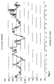
- FIG. 2 shows a diagram of time and number of cycles in a prior art system
- FIG. 3 shows a schematic diagram of a preferred embodiment of a control system according to the invention.
- FIG. 4 shows a diagram of time and number of cycles in a control system according to the invention.
- a prior art control system ( FIG. 1 ) comprises a central control unit 10 for performing cyclical machine program sequences, such as a PLC.
- the central control unit 10 communicates with a data processing means 12 , such as an IPC.
- the IPC 12 is connected with a display 14 such that the IPC 12 , together with the display 14 , forms a visualization means.
- the PLC 10 is connected with inputs/outputs 16 which, in turn, are connected with an injection molding machine 18 .
- the machine program sequences are performed by the PLC, wherein the machine program sequences are cyclically executed.
- the PLC 10 is connected with a comparator 20 which processes interrupt signals.
- the generation of interrupt signals interrupts the cyclical sequence of the PLC and thus has the drawbacks described above.
- cycle times as shown in FIG. 2 can be realized.
- the diagram of FIG. 2 shows relatively strong variations in the cycle times during different injection shots, i.e. filling of the injection mold. Cycle time variations of up to 80 ms occur.
- a preferred embodiment of the control system according to the invention comprises an IPC 22 in which on the one hand the control unit for a visualization means 24 , i.e. the control unit for a display 25 , and on the other hand the PLC 26 for executing cyclical machine program sequences are integrated.
- an additional control unit 28 configured as an FPGA is arranged independently of the central control unit 26 .
- the FPGA 28 and the PLC 26 are connected with the input/output connectors 16 .
- the FPGA 28 may also be arranged between the PLC 26 and the connectors 16 , wherein the signal from and/or to the PLC 26 pass through the FPGA 28 .
- the control system according to the invention ( FIG. 3 ) allows the cycle time variations shown in FIG. 4 to be realized. As can be seen from FIG. 4 , the cycle time variations are considerably smaller. Here, the cycle time variations amount to max. 20 ms.
Landscapes
- Engineering & Computer Science (AREA)
- Manufacturing & Machinery (AREA)
- Mechanical Engineering (AREA)
- Injection Moulding Of Plastics Or The Like (AREA)
Abstract
Description
Claims (14)
Applications Claiming Priority (2)
| Application Number | Priority Date | Filing Date | Title |
|---|---|---|---|
| DE102005054769.9 | 2005-11-15 | ||
| DE102005054769A DE102005054769B3 (en) | 2005-11-17 | 2005-11-17 | Control system and control method for an injection molding machine |
Publications (2)
| Publication Number | Publication Date |
|---|---|
| US20070112457A1 US20070112457A1 (en) | 2007-05-17 |
| US7321800B2 true US7321800B2 (en) | 2008-01-22 |
Family
ID=38041936
Family Applications (1)
| Application Number | Title | Priority Date | Filing Date |
|---|---|---|---|
| US11/293,339 Expired - Fee Related US7321800B2 (en) | 2005-11-17 | 2005-12-02 | Control system and method of controlling an injection molding machine |
Country Status (2)
| Country | Link |
|---|---|
| US (1) | US7321800B2 (en) |
| DE (1) | DE102005054769B3 (en) |
Cited By (1)
| Publication number | Priority date | Publication date | Assignee | Title |
|---|---|---|---|---|
| US20110230983A1 (en) * | 2010-03-19 | 2011-09-22 | Sick Ag | Apparatus for the generation of a program for a programmable logic controller, a programming unit and method for programming a programmable logic controller |
Families Citing this family (5)
| Publication number | Priority date | Publication date | Assignee | Title |
|---|---|---|---|---|
| DE102006002296B3 (en) | 2006-01-18 | 2007-07-26 | Dr. Boy Gmbh & Co. Kg | Control system and control method for injection molding machines |
| US20150224681A1 (en) * | 2012-07-24 | 2015-08-13 | Surface Generation Limited | Control system for tooling |
| CN106891496B (en) * | 2015-10-27 | 2019-04-12 | 深圳市亚启科技有限公司 | High-speed injection molding machine based on FPGA projects position capture systems and method |
| AT520167B1 (en) | 2017-07-12 | 2019-05-15 | Engel Austria Gmbh | Hydraulic system for a molding machine |
| CN111516233A (en) * | 2020-04-17 | 2020-08-11 | 汕头大学 | Injection molding machine data preprocessing method and system |
Citations (1)
| Publication number | Priority date | Publication date | Assignee | Title |
|---|---|---|---|---|
| US20040133285A1 (en) * | 2002-11-02 | 2004-07-08 | Mannesmann Plastics Machinery Gmbh | Control system for a plastics processing machine |
Family Cites Families (3)
| Publication number | Priority date | Publication date | Assignee | Title |
|---|---|---|---|---|
| DE4429304C1 (en) * | 1993-09-11 | 1995-06-14 | Procontrol Ag | Multiple motor drive control |
| US6272398B1 (en) * | 1998-09-21 | 2001-08-07 | Siebolt Hettinga | Processor-based process control system with intuitive programming capabilities |
| DE10239759A1 (en) * | 2002-08-29 | 2004-03-18 | Demag Ergotech Gmbh | Installation and operating unit for an injection molding machine comprises one or more machine controls, data carriers and programmes, at least one server and operating terminals |
-
2005
- 2005-11-17 DE DE102005054769A patent/DE102005054769B3/en not_active Revoked
- 2005-12-02 US US11/293,339 patent/US7321800B2/en not_active Expired - Fee Related
Patent Citations (1)
| Publication number | Priority date | Publication date | Assignee | Title |
|---|---|---|---|---|
| US20040133285A1 (en) * | 2002-11-02 | 2004-07-08 | Mannesmann Plastics Machinery Gmbh | Control system for a plastics processing machine |
Cited By (2)
| Publication number | Priority date | Publication date | Assignee | Title |
|---|---|---|---|---|
| US20110230983A1 (en) * | 2010-03-19 | 2011-09-22 | Sick Ag | Apparatus for the generation of a program for a programmable logic controller, a programming unit and method for programming a programmable logic controller |
| US8694135B2 (en) * | 2010-03-19 | 2014-04-08 | Sick Ag | Programming programmable logic controllers using exertion influence in establishing matrix parameters |
Also Published As
| Publication number | Publication date |
|---|---|
| DE102005054769B3 (en) | 2007-06-06 |
| US20070112457A1 (en) | 2007-05-17 |
Similar Documents
| Publication | Publication Date | Title |
|---|---|---|
| US7970488B2 (en) | Machine tool workpiece inspection system | |
| US4884373A (en) | Numerically controlled machine tool | |
| JP6469065B2 (en) | Machine learning device and machining time prediction device | |
| CN101377671B (en) | Numerical controller with interference check function | |
| EP3106944B1 (en) | Method for controlling shape measuring apparatus | |
| US4096770A (en) | Method and apparatus for modifying the position of a machine slide to compensate for different following errors | |
| Martinova et al. | Diagnostics and forecasting of cutting tool wear at CNC machines | |
| US9715225B2 (en) | Numerical controller for smoothing tool path in operation based on table format data | |
| US11919163B2 (en) | Method for validating programmed execution sequences or teaching programs for a robot in a working cell, and a robot and/or robot controller for said method | |
| US7321800B2 (en) | Control system and method of controlling an injection molding machine | |
| CN101590688B (en) | Abnormity detector of injection molding machine | |
| CN107966956A (en) | Numerical control device | |
| CN100515725C (en) | Controllers for injection molding machines | |
| US5023028A (en) | Method and apparatus for controlling a back pressure of a motor-driven injection molding machine | |
| JP5927264B2 (en) | Injection molding system | |
| US20210157320A1 (en) | Motor control apparatus, numerical control apparatus, robot controller, and integrated controller system | |
| Pritschow et al. | Open system architecture for drives | |
| US3794900A (en) | Pulse interpolation systems | |
| CN107450479A (en) | A kind of control system of digital control system timing synchronization | |
| JP4982273B2 (en) | Data display method of molding machine | |
| JP3881633B2 (en) | Mold clamping control method of injection molding machine | |
| CN106970652B (en) | Motion controller | |
| JPWO2022075244A5 (en) | ||
| JP2004330529A (en) | Mold clamping control method for injection molding machine | |
| SU1055627A1 (en) | Device for positioning and monitoring dimensions wear of cutting tool in n/c machines |
Legal Events
| Date | Code | Title | Description |
|---|---|---|---|
| AS | Assignment |
Owner name: DR. BOYGMBH & CO. KG, GERMANY Free format text: ASSIGNMENT OF ASSIGNORS INTEREST;ASSIGNOR:LUDWIG, FRANZ JOSEF;REEL/FRAME:017611/0485 Effective date: 20051212 Owner name: DR. BOYGMBH & CO. KG,GERMANY Free format text: ASSIGNMENT OF ASSIGNORS INTEREST;ASSIGNOR:LUDWIG, FRANZ JOSEF;REEL/FRAME:017611/0485 Effective date: 20051212 |
|
| STCF | Information on status: patent grant |
Free format text: PATENTED CASE |
|
| FPAY | Fee payment |
Year of fee payment: 4 |
|
| FPAY | Fee payment |
Year of fee payment: 8 |
|
| FEPP | Fee payment procedure |
Free format text: MAINTENANCE FEE REMINDER MAILED (ORIGINAL EVENT CODE: REM.); ENTITY STATUS OF PATENT OWNER: SMALL ENTITY |
|
| LAPS | Lapse for failure to pay maintenance fees |
Free format text: PATENT EXPIRED FOR FAILURE TO PAY MAINTENANCE FEES (ORIGINAL EVENT CODE: EXP.); ENTITY STATUS OF PATENT OWNER: SMALL ENTITY |
|
| STCH | Information on status: patent discontinuation |
Free format text: PATENT EXPIRED DUE TO NONPAYMENT OF MAINTENANCE FEES UNDER 37 CFR 1.362 |
|
| FP | Lapsed due to failure to pay maintenance fee |
Effective date: 20200122 |