US7315253B1 - Security device and transponder - Google Patents
Security device and transponder Download PDFInfo
- Publication number
- US7315253B1 US7315253B1 US11/027,938 US2793805A US7315253B1 US 7315253 B1 US7315253 B1 US 7315253B1 US 2793805 A US2793805 A US 2793805A US 7315253 B1 US7315253 B1 US 7315253B1
- Authority
- US
- United States
- Prior art keywords
- security device
- container
- transponder
- disk
- security
- Prior art date
- Legal status (The legal status is an assumption and is not a legal conclusion. Google has not performed a legal analysis and makes no representation as to the accuracy of the status listed.)
- Expired - Fee Related, expires
Links
Images


Classifications
-
- G—PHYSICS
- G08—SIGNALLING
- G08B—SIGNALLING SYSTEMS, e.g. PERSONAL CALLING SYSTEMS; ORDER TELEGRAPHS; ALARM SYSTEMS
- G08B13/00—Burglar, theft or intruder alarms
- G08B13/22—Electrical actuation
- G08B13/24—Electrical actuation by interference with electromagnetic field distribution
- G08B13/2402—Electronic Article Surveillance [EAS], i.e. systems using tags for detecting removal of a tagged item from a secure area, e.g. tags for detecting shoplifting
- G08B13/2428—Tag details
- G08B13/2434—Tag housing and attachment details
Definitions
- a preferred embodiment of the invention relates to a security device and/or a transponder for attachment to a container, for example to a container housing a disk such as a CD or DVD, to help in preventing or deterring its theft from a retail outlet.
- EAS Electronic Article Surveillance
- AM acoustic magnetic
- RF Radio Frequency
- the tag acts as a transponder, i.e., it is energized on receipt of radiation, e.g., from an alarm unit, and then transmits a signal back automatically, e.g., to the alarm unit.
- Other types of tags are also known, e.g., Radio Frequency ID (RFID) tags, also known as “intelligent tags” as they send additional information with the signal they transmit.
- RFID Radio Frequency ID
- RF tags comprising flat coils can be used but as they are relatively large it is difficult to mount them in a position when used with a container such as a CD or DVD box where they do not suffer from shielding.
- a preferred embodiment of the invention aims to provide an arrangement of a security device which helps avoid or reduce this problem.
- a security device for attachment to a container having external walls such that at least a signal receiving and/or transmitting portion thereof is located externally of or adjacent to one of said external walls, the security device being arranged to trigger an alarm signal if the container is moved within the range of an alarm unit with the security device attached thereto, the security device having a releasable locking mechanism to secure it to the container such that release of the locking mechanisms requires the use of authorized release means.
- a security device for attachment to apparatus adapted to hold one or more articles which includes a layer which is non-transparent to electromagnetic radiation, the security device having a portion for receiving and/or transmitting electromagnetic radiation so as to trigger an alarm signal if the apparatus is moved within the range of an alarm unit with the security device attached thereto, said portion being located on the device such that it lies in the vicinity of a window in said layer or a gap between two such layers so as to be able to receive and/or transmit electromagnetic radiation through said window or gap when the device is attached to said apparatus.
- the security device is of a type such as described and claimed in WO 02/39451, which is hereby incorporated by reference herein in its entirety, with a non-planar RF transponder mounted thereon, preferably on (or within) a portion thereof which remains externally of a container to which the device is mounted.
- a security device may simply have a locking mechanism to releasably secure it within the container but preferably also serves to secure the contents of the container, e.g. a disk, to the container and/or to secure the container in a closed configuration.
- a preferred embodiment of the invention also relates to such a security device in combination with a container adapted to receive the device.
- a preferred embodiment of the invention also relates to a device arranged to receive signal receiving and/or transmitting means such that, when said signal receiving and/or transmitting means is mounted therein, a security device such as that detailed above is provided.
- the present invention provides a transponder comprising a substantially flat strip of magnetic material and an elongate electrical conductor wound around the strip along at least part of its length.
- the transponder preferably is a radio frequency (RF) transponder.
- Preferred frequency bands include the kilohertz (kHz) and megahertz (MHz) bands.
- kHz kilohertz
- MHz megahertz
- An example of a particularly preferred frequency is 8.2 MHz, but other frequencies may apply.
- a fourth aspect of a preferred embodiment of the invention provides an RF transponder in the form of a substantially flat strip that in use generates a magnetic dipole, wherein the axis of the dipole lies along at least part of the length of the strip.
- the transponder according to the second aspect of a preferred embodiment of the invention may be a transponder according to the first aspect of a preferred embodiment of the invention, and vice versa.
- a fifth aspect of a preferred embodiment of the invention provides a security device comprising a substantially flat member and a transponder according to the first or second aspect of a preferred embodiment of the invention attached thereto.
- the transponder of the security device preferably is arranged to trigger an alarm if the security device is brought into a magnetic field of an alarm unit.
- the security device therefore preferably is an anti-theft device for deterring the theft of goods from stores and the like.
- the substantially flat strip of the transponder preferably is substantially co-planar with, or substantially parallel to, the substantially flat member of the security device.
- the transponder may be mounted on or in the flat member of the security device, or otherwise embedded in the flat member of the security device.
- the transponder is at least partially embedded in a polymer material (e.g. an epoxy resin) in or on the flat member of the security device.
- the polymer material may be loaded with a magnetic filler material, e.g. a ferrite material (for example as described below).
- a magnetic filler material may contribute to the generation of the magnetic dipole by the transponder, particularly in the event that the strip of magnetic material breaks in use, for example.
- the security device preferably is adapted to be attached to a container or other apparatus adapted to hold a product or other article.
- a preferred embodiment of the invention has particular relevance to disks such as CDs and DVDs, and the article or product preferably comprises one or more CDs or DVDs.
- a preferred embodiment of the invention is, however, relevant to other types of product and other types of article.
- the security device includes a locking mechanism to secure it to a container or other apparatus.
- the locking mechanism is releasable, such that the security device may be removed from the container or other apparatus.
- the release of the locking mechanism may require the use of authorised release means.
- a locking mechanism also serves to secure the product or other article, e.g. a disk, to the container or other apparatus, and/or to secure the container in a closed configuration.
- the security device is of a type such as described and claimed in international patent application WO 02/39451, but including a transponder as described herein.
- a security device may have the above-mentioned locking mechanism to releasably secure it within a container.
- the product or other article may include an electrically conductive layer or region.
- a CD or DVD generally includes a metal layer embedded therein (for reflecting laser light used by the CD or DVD player in use).
- This causes a problem in that the functioning of conventional transponders based upon magnetic dipoles normally is disrupted by the presence of such metal layers, because eddy currents generated in the metal layer by the magnetic dipole of the transponder cause attenuation of the magnetic moment generated by the transponder.
- the magnetic field generated by the conventional transponder when the transponder is placed in the magnetic field of an alarm unit may be insufficient to trigger the alarm.
- the transponder according to the present invention is in the form of a substantially flat strip whose magnetic dipole preferably lies substantially along at least part of the length thereof. Consequently, an advantage of the present invention is that by orienting the security device such that the magnetic dipole of its transponder lies approximately parallel to the electrically conductive layer or region, the attenuation of the magnetic moment generated by the transponder may be insufficient to disrupt the correct functioning of the transponder. This is because, by orienting the transponder such that its magnetic dipole is approximately parallel to the electrically conductive layer or region, the eddy currents generated by the transponder in the electrically conductive layer or region may be minimised. This is explained further below.
- a sixth aspect of a preferred embodiment of the invention provides a kit of parts comprising an apparatus for holding one or more articles, and a security device according to the third aspect of a preferred embodiment of the invention adapted to be secured thereto.
- the kit is arranged such that when the security device is secured to the apparatus, the magnetic dipole generated in use by the transponder is oriented substantially parallel to an electrically conductive layer or region of an article held by the apparatus.
- the longitudinal centre of the axis of the magnetic dipole generated by the transponder preferably is adjacent to a window in the electrically conductive layer of the disk (e.g. a window around the central hole provided in the disk). In this way, the generation of eddy currents in the electrically conductive layer by the transponder may be minimised.
- the axis of the magnetic dipole generated by the transponder may extend between two such disks.
- the kit may be arranged such that when the security device is secured to the apparatus, the transponder of the security device is adjacent to an external wall of the apparatus.
- the transponder of the security device is housed within the apparatus, e.g. adjacent to an external wall of the apparatus.
- the flat strip of magnetic material of the transponder may, for example, have a simple rectangular shape.
- part of the length of the strip may have a narrower width than the remainder of the strip.
- the strip may have an approximate H-shape.
- the elongate electrical conductor may be wound around only the narrower part of the strip.
- the flat strip of magnetic material of the transponder preferably is a ferromagnetic material or a ferrimagnetic material.
- Preferred such materials include ferrites, especially a mixed oxide of iron and nickel and/or zinc and/or cobalt and/or manganese.
- Such materials generally comprise ceramics. Examples of two particularly preferred nickel-zinc ferrites, chosen by experimentation by the present inventors, are: F16 supplied by TT Electronics and 4C65 supplied by Philips.
- the flat strip of magnetic material of the transponder is susceptible to damage.
- the strip of magnetic material may be provided with one or more region(s) of weakness, whereby the strip is arranged to break preferentially at such region(s) when subjected to mechanical distortion or shock.
- the or each region of weakness is located away from, or adjacent to, a region of the magnetic strip around which the elongate electrical conductor is wound.
- each region of weakness may comprise a score mark (e.g. a groove) provided in the surface of the strip, or a cut-away region (e.g. a V-cut) of the strip, for example.
- the above-mentioned polymer material loaded with magnetic filler may also have the effect of helping to preserve at least some of the magnetic field generated by the transponder, in the event that the flat strip of the transponder breaks. If some or all of the flat strip is at least partially embedded in such filled polymer material, in the event of a gap being formed in the strip due to a fracture, at least some of the magnetic field may be channeled through the polymer material in the region of the fracture, for example.
- the elongate electrical conductor preferably comprises a metal wire.
- the wire or other conductor may comprise a single strand or strip.
- the wire comprises a plurality of strands, and most preferably is a multi-strand wire.
- the multi-strand wire may be woven or braided, for example, and preferably is Litz wire.
- Such multi-stranded wires have the advantage of reducing eddy current effects, for example due to skin effects and/or proximity effects.
- the diameter of each strand of wire preferably is at least 0.01 mm, more preferably at least 0.02 mm, especially at least 0.03 mm.
- the diameter of each strand of wire preferably is no greater than 0.06 mm, more preferably no greater than 0.05 mm, especially no greater than 0.045 mm, and for example 0.04 mm.
- the wire comprises at least 15 strands, more preferably at least 20 strands, and preferably no more than 50 strands, more preferably no more than 40 strands, for example 25 strands. Such wires have been chosen by experimentation by the present inventors.
- the winding density of the windings of the elongate electrical conductor around the strip of magnetic material has an important effect upon the performance of the transponder.
- the inventors have found that a winding density of at least 0.4 turns/mm and no greater than 1.0 turns/mm provides an optimum range. More preferably, the winding density range is between 0.44 turns/mm and 0.96 turns/mm, especially between 0.6 turns/mm and 0.76 turns/mm, for example 0.68 turns/mm.
- Such winding densities have been found by the present inventors to maximise the magnetic filed generated by the transponder. (For the avoidance of doubt, one “turn” is a single complete winding revolution around the strip.)
- the transponder preferably includes a capacitor.
- the capacitor preferably is electrically connected between ends of the elongate electrical conductor that is wound around the strip of magnetic material.
- the capacitance of the capacitor preferably is no more than 100 pF, but the choice of capacitance will depend upon the particular requirements of the transponder, and may be determined by the skilled person via trial and error.
- the capacitance is generally chosen to make the transponder resonate at or near the frequency of interest; as the skilled person knows, if the inductance of the electrical conductor is L and the frequency of interest is f then the capacitance preferably should be close to
- FIG. 1 is a perspective view of part of a security device according to a first embodiment of the invention
- FIG. 2 is an exploded perspective view corresponding to that shown in FIG. 1 ;
- FIG. 3 is an exploded perspective view from another direction of the part shown in FIG. 1 ;
- FIG. 4 is a plan view illustrating the use of a device as shown on FIGS. 1-3 with a CD or DVD container;
- FIG. 5 is a cross-sectional view taken along line VI-VI of FIG. 4 (with the security device inserted further into the container);
- FIG. 6 is a plan view of a further embodiment of the invention showing the security device being installed in a DVD container (with the DVD omitted for clarity);
- FIG. 7 is a similar view to FIG. 6 but shows the position of the security device when fully inserted into the container;
- FIG. 8 is a cross-sectional view taken on line A-A of FIG. 7 (but also showing a disk held on the apparatus);
- FIG. 9 is a similar cross-sectional view through a different kind of DVD container.
- FIG. 10 is a perspective view of part of a security device according to an embodiment of the invention.
- FIG. 11 is a plan view illustrating the use of a security device similar to that shown in FIG. 1 , with a CD or DVD container;
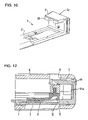
- FIG. 12 is a cross-sectional view of part of a security device similar to that shown in FIGS. 10 and 11 inserted into a container as shown in FIG. 11 ;
- FIG. 13 is a plan view similar to FIG. 11 , but showing the position of the security device when fully inserted into the container;
- FIG. 14 is a schematic cross-section on line A-A of FIG. 13 ;
- FIG. 15 is a similar schematic cross-section to that of FIG. 14 , through another form of disk holding means of a container;
- FIGS. 16A and 16B show two schematic illustrations of preferred transponders according to a preferred embodiment of the invention.
- FIG. 17 is a schematic illustration of the magnetic dipole generated by the transponders shown in FIGS. 16A and 16B ;
- FIGS. 18A and 18B show two schematic illustrations comparing the generation of eddy currents in a metal layer of a DVD disk, by a prior art transponder (view (a)) and a transponder according to the present invention (view (b)).
- FIGS. 1-5 The embodiment of the security device illustrated in FIGS. 1-5 is designed for use with a CD or DVD container of the type described in WO 02/39451, the disclosure of which is incorporated herein.
- the security device may, however, be used with other types of container.
- the security tag 1 shown in FIGS. 1-3 comprises a long arm 2 and a short arm 3 both arms projecting from a head portion 4 .
- the long and short arm 2 , 3 may be similar to those described in WO 02/39451.
- the long arm 2 is designed to be inserted through an aperture or slot 5 in a side wall 6 of a base portion of a DVD container. Preferably, it extends across the base portion 7 and interacts with disk-holding means 8 on the base portion 7 to lock the disk (not shown) onto the base portion 7 as described in WO 02/39451.
- FIG. 4 the long arm 2 is designed to be inserted through an aperture or slot 5 in a side wall 6 of a base portion of a DVD container. Preferably, it extends across the base portion 7 and interacts with disk-holding means 8 on the base portion 7 to lock the disk (not shown) onto the base portion 7 as described in WO 02/39451.
- the short arm 3 is designed to be inserted through an aperture or slot 9 in a side wall of a lid portion 10 of the container which is hingedly attached to the base portion 7 along an edge thereof so as to hold the lid portion 10 in a closed position relative to the base portion.
- the arms 2 , 3 and the head portion 4 are preferably formed of a plastics material.
- the long arm 2 is provided with a releasable locking mechanism which, once the long arm has been inserted into the container, locks the device to the container until it is released therefrom, e.g. by a magnetic release apparatus, such as may be provided behind the counter in a retail outlet.
- the locking mechanism comprises a metal pivot arm 11 which, once the security tag 1 has been inserted into the container, engages a detent 12 within the base portion 7 so providing a snap-fit which prevents withdrawal of the security device 1 from the container until the pivot arm 11 is moved, e.g. by a magnetic release device or a specially shaped key, out of engagement with the detent 12 (the metal pivot arm 11 is not shown in FIGS. 1-3 ).
- This and other locking mechanisms are described further in WO 02/039451.
- the locking mechanism is preferably arranged to be capable of repeated locking and unlocking so the device can be re-used many times.
- the security device described in W002/39451 holds an AM flatstrip type security tag within a recess towards the distal end of the long arm 2 thereof.
- the security device illustrated in FIGS. 1-5 has a non-planar RF type security tag in the form of a coil 13 wound around a magnetic core 14 , e.g. a ferrite rod, mounted within the head portion 4 .
- the coil 13 is connected to a capacitor (not shown) located adjacent thereto.
- WO 02/39451 discloses a head portion which is essentially planar and which has a metal plate therein to assist in withdrawal of the security tag from the container by magnetic means once the locking mechanism securing it within the container has been released.
- the security device described herein comprises an enlarged head portion 4 which is shaped to accommodate the ferrite rod 14 with a coil 13 wound thereabout.
- the ferrite rod 14 typically has a length in the range 15-20 mm and a diameter (including the coil) of around 5-10 mm.
- This ferrite rod 14 and coil 13 act as a transponder for receiving a radio frequency signal from an alarm unit and transmitting a signal back to the alarm unit.
- the transponder By mounting the transponder externally of the container it is well positioned to communicate with the alarm unit. In particular, when mounted in the position shown adjacent a narrow edge of the container, it is located substantially within the plane occupied by a CD or DVD (or other contents of the container) held within the container.
- the transponder is thus located substantially co-planar with the metal layer within the CD or DVD (or other contents of the container) so is not shielded by the metal layer whatever the orientation of the container relative to the alarm unit.
- the transponder is located remote from the contents of the container. As the transponder include a magnetic member this may be desirable to avoid damaging the contents of the container if they are susceptible to magnetic fields.
- transponder externally also avoids occupying space within the container so it does not interfere with the contents or reduce the volume available for housing contents within the container.
- the security device can also be installed in the container when the latter is in a closed configuration.
- the enlarged head portion 4 projects from the container and thus increases its external dimension but only in a localised area along the opening side of the container so has a negligible effect upon the storage or shelving requirements for displaying the product within a retail outlet.
- the head portion 4 is also preferably mounted within a finger recess 15 provided along the opening edge of the container to reduce the distance by which it projects beyond the external dimensions of the container.
- the transponder may be mounted externally in other locations on the container or mounted adjacent an external wall of the container. In the latter case, it may be housed within the container and/or so that it does not project beyond the external dimensions thereof. An example of this is described further below with reference to FIG. 6 .
- the ferrite rod 14 performs two functions. First, it forms part of the RF transponder and, secondly, as it is magnetic, it can be used to assist in withdrawal of the security device from the container by magnetic means so performs the role of the metal plate provided in the head portion 4 such as described in WO 02/39451. As ferrite is less strongly attracted by a magnetic force than a metal insert, to enable reliable functioning of the release apparatus in withdrawing the device from a container, the type of ferrite used preferably has high ferromagnetic properties and it is preferably located as close as possible to the outermost facing surface of the head 4 . If the security device is intended to be re-used, the ferrite rod 14 is also preferably magnetically saturated so that it retains its magnetism and is not deactivated in the presence of a magnetic field.
- the head portion comprises a cover 16 which fits onto the security device to locate the transponder and hold it in place within the head portion 4 .
- the cover 16 is preferably a snap-fit onto the device so that once it is located in place it cannot be removed without breaking open the head portion 4 or by the application of a specialised release tool or key.
- the outer wall of the cover 16 is thin, e.g. 1 mm or less or 0.5 mm or less in thickness, so the ferrite rod 14 is located as close as possible to the external surface thereof to maximise the magnetic force applied thereto when the head 4 is brought up to a magnet in the release apparatus.
- FIGS. 2 and 3 show a cover 16 having four projecting arms 16 A, 16 B, 16 C and 16 D which snap-fit into sockets or recesses (not shown) provided in the head portion 4 of the security device.
- the cover 16 and the outer end 4 A of the head portion 4 are shaped to locate the cylindrical ferrite rod and secure it within the head portion 4 .
- the ends 14 A and 14 B of the ferrite rod 14 are exposed on each side of the head portion 4 to enable the length of the rod to be maximised within the limited space available.
- the ferrite rod 14 may be completely concealed within the head portion 4 .
- the head portion 4 is preferably shaped so as to make it difficult to obtain a purchase thereon to try to pull the security tag out of the container without authorised release of the locking mechanism. To this end, it preferably has a curved outer surface as shown which, in use, faces outward from the container. This curved form also helps minimise the amount of plastic shielding the ferrite rod 14 from a magnetic field applied thereto when magnetic release apparatus is used to withdraw the device from the container. In another embodiment (not shown) the ends of the head portion 4 adjacent the ends of the ferrite rod 14 may also have a curved form for the same reason.
- RF security tags may be designed to be deactivated by a deactivation unit behind the counter in a retail outlet in which case there is no need to remove the security tag from the container when a customer purchases the container.
- the security tag may be designed for a single use only and disposed of by the customer.
- security tags can be deactivated and then reactivated so they can be re-used.
- the retail outlet may deactivate the tag and then remove it before the customer takes the container away.
- the preferred form of RF security tag for use with the arrangement described herein is a permanent form which cannot be deactivated as this increases the level of security provided by the tag.
- the tag must be removed from the container prior to the customer taking the container out of the store.
- security tags are designed for multiple re-use, there are less cost restraints on its design so higher quality components may be used.
- the RF security tag can be arranged to send an identification signal or other data to the alarm unit but a signal simply indicating its presence is sufficient to trigger an alarm.
- Magnetic release apparatus for releasing a security device such as that described herein is described in WO 02/39451 so will not be described further herein.
- the container with which the security device is used may typically be provided with an outer wrapping, e.g. a plastic shrink-wrapping.
- the security tag 1 is designed to pierce such a wrapping so the security device can be installed after application of the wrapping.
- the long and short arms 2 and 3 thus preferably have pointed ends 2 A, 3 A or are shaped so as to easily pierce such a wrapping.
- the arms 2 and 3 are relatively thin and as the area in which they pierce the wrapping is, in use, concealed by the head portion 4 of the device, this does not prejudice the integrity of the wrapper nor its appearance and the shrink-wrapping remains intact. It thus still provides tamper evidence and provides re-assurance to the customer that the contents have not been interfered with.
- the arrangement described above thus enables a non-planar form of security tag, such as an RF device with a cylindrical core, to be used in relation to a container in a manner which avoids, or significantly reduces, the problem of shielding, is small enough to be mounted on a security device which is used to inhibit removal of a product from the container, e.g. a security device such as that described in WO 02/39451, without compromising the level of security provided by this device, yet whose performance is sufficient to provide reliable operation in triggering an alarm.
- a security device such as that described in WO 02/39451
- the arrangement described also has the advantage that it can still be used with existing release apparatus used to release a security device from the container, e.g. release apparatus such as that described in WO 02/39451.
- a component of the security tag e.g. a ferrite rod, is used both as part of the transponder and to assist in withdrawal of the security device from the container by magnetic release apparatus.
- the arrangement thus provides a practical way of using an RF-type EAS device in relation to security devices of the type described in WO 02/39451 so they can be used in retail outlets employing RF alarm systems as well as those using AM alarm systems.
- the security device may, if desired, be arranged to receive both an AM tag and an RF tag. The required form of tag can then be mounted thereon, or even both types if desired.
- FIGS. 6 and 7 illustrate another way of mounting an RF transponder 20 on a security device 2 of the type described in W002/39451.
- This embodiment is based upon the realisation that another way to avoid, or reduce, the problem of shielding caused by the metal layer within a disk 21 such as a CD or DVD (see FIG. 8 ) is to mount the RF transponder 20 in a position which is aligned with the central region of the disk 21 .
- Such disks have an aperture 21 A in the centre thereof typically of a diameter of 15 mm.
- a transponder 20 located in the vicinity of the aperture in such a disk will be able to receive and send signals in most directions as such signals can pass through the aperture 21 A in the disk so it can communicate with an alarm system located on either side of the disk 21 .
- many such disks have a region 21 B around the central aperture 21 A which is not provided with a metal layer 21 C.
- the aperture in the metal layer 21 C of a disk is often greater than the aperture 21 A in the plastic layers between which the metal layer 21 C is sandwiched.
- the diameter of this substantially metal free area 21 B may be up to 38 mm in diameter but, more typically, is around 30 mm in diameter. There is, therefore, window of appreciable size in the centre of the disk 21 through which signals can be received by and sent from an RF transponder 20 located in that vicinity.
- the RF transponder 20 is also highly desirable for the RF transponder 20 to be carried by the security device 2 so that it can be locked within the container and once removed can be re-used in another container.
- the RF transponder 20 is thus mounted on the security device 2 in a position such that, in use, when the security device 2 is installed within the container 7 , it lies in the vicinity of the window described above in the metal layer 21 C of the disk 21 .
- the security device 2 typically has a width similar to the diameter of the central hole 21 A of the disk.
- a transponder 20 with a width of 15 mm and a length of 15 to 30 mm can be mounted on the long arm of the security device 2 in a position such that, when installed, it lies under the central area of the disk 21 .
- An RF transponder 20 of the above dimension can be provided either in the form of a flat coil of wire (or other electrical conductors) similar to that described above but wound in elongate loops rather in circles so as to fit within a 15 ⁇ 30 mm area on the security device 2 or in the form of a coil wound around a thin, substantially flat, ferrite core.
- FIG. 8 shows a cross-section on line A-A of FIG. 7 through the disk holding means 8 , a disk 21 held thereon and a security device 2 located under the disk holding means 8 with an RF transponder 20 mounted thereon so as to be located adjacent the disk 21 and in the vicinity of the central aperture 21 A of the disk.
- FIG. 8 also shows the typical extent of a metal layer 21 C embedded within the disk 21 .
- FIG. 9 shows a similar cross-section through another form of disk holding means 8 ′ which provides more space between the above the security device 2 in the vicinity of the central hole 21 A of the disk 21 and which would thus enable a preferred embodiment of the invention to be implemented with an RF transponder 20 ′ of slightly greater thickness (perpendicular to the plane of the disk) although, in cases where the security device 2 is inserted through a slot in the extended wall of the container (e.g. slot 5 shown in FIG. 6 ), this would require the slot to be made slightly larger too.
- the container may be adapted to hold two or more such articles, e.g. side by side, in which case the security device is arranged so that the RF transponder lies in the vicinity of a gap between the articles.
- FIGS. 10-13 The embodiment of the security device illustrated in FIGS. 10-13 is designed for use with a CD or DVD container of the type described in WO 02/39451, the entire disclosure of which is incorporated herein by reference.
- the security device may, however, be used with other types of container.
- the security device 1 shown in FIGS. 10-13 comprises a long arm 2 and a short arm 3 , both arms projecting from a head portion 4 .
- the long and short arms 2 , 3 may be similar to those described in WO 02/39451.
- the long arm 2 is designed to be inserted through an aperture or slot 5 in a side wall 6 of a base portion of a CD or DVD container. Preferably, it extends across the base portion 7 and interacts with disk-holding means 8 on the base portion 7 to lock the disk (not shown) onto the base portion 7 as described in WO 02/39451.
- FIG. 11 the long arm 2 is designed to be inserted through an aperture or slot 5 in a side wall 6 of a base portion of a CD or DVD container. Preferably, it extends across the base portion 7 and interacts with disk-holding means 8 on the base portion 7 to lock the disk (not shown) onto the base portion 7 as described in WO 02/39451.
- the short arm 3 is designed to be inserted through an aperture or slot 9 in a side wall of a lid portion 10 of the container which is hingedly attached to the base portion 7 along an edge thereof so as to hold the lid portion 10 in a closed position relative to the base portion.
- the arms 2 , 3 and the head portion 4 preferably are formed of a plastic material, for example a polyamide (e.g. Nylon) or ABS (an acrylonitrile-butadiene-styrene copolymer).
- the material may contain a reinforcement or other filler, for example a fiber filler, especially glass fibers.
- the long arm 2 is provided with a releasable locking mechanism which, once the long arm has been inserted into the container, locks the device to the container until it is released therefrom, e.g. by a magnetic release apparatus, such as may be provided behind the counter in a retail outlet.
- the locking mechanism comprises a metal pivot arm 11 which, once the security device 1 has been inserted into the container, engages a detent 12 within the base portion 7 so providing a snap-fit which prevents withdrawal of the security device 1 from the container until the pivot arm 11 is moved, e.g. by a magnetic release device or a specially shaped key, out of engagement with the detent 12 .
- the metal pivot arm 11 is not shown in FIG. 10 ).
- This and other locking mechanisms are described further in WO 02/039451.
- the locking mechanism preferably is arranged to be capable of repeated locking and unlocking so the device can be re-used many times.
- the head portion 4 has a metal plate 4 a therein to assist in withdrawal of the security tag from the container by magnetic means once the locking mechanism securing it within the container has been released.
- the security device can be, and preferably is, installed in the container when the latter is in a closed configuration.
- the head portion 4 preferably is mounted within a finger recess 15 provided along the opening edge of the container to reduce the distance by which it projects beyond the external dimensions of the container.
- RF security devices may be designed to be deactivated by a deactivation unit behind the counter in a retail outlet in which case there is no need to remove the security tag from the container when a customer purchases the container.
- the security tag may be designed for a single use only and disposed of by the customer.
- Other types of security tags can be deactivated and then reactivated so they can be re-used.
- the retail outlet may deactivate the tag and then remove it before the customer takes the container away.
- the preferred form of RF security tag for use with the arrangement described herein is a permanent form which cannot be deactivated as this increases the level of security provided by the tag. In this case, the tag must be removed from the container prior to the customer taking the container out of the store.
- security tags are designed for multiple re-use, there are less cost restraints on its design so higher quality components may be used.
- the RF security tag can be arranged to send an identification signal or other data to the alarm unit but a signal simply indicating its presence is sufficient to trigger an alarm.
- a magnetic release apparatus for releasing a security device such as that described herein is described in WO 02/39451 so will not be described further herein.
- the container with which the security device is used may typically be provided with an outer wrapping, e.g. a plastic shrink-wrapping.
- the security device 1 is designed to pierce such a wrapping so the security device can be installed after application of the wrapping.
- the long and short arms 2 and 3 thus preferably have pointed ends, or are shaped so as to easily pierce such a wrapping. As the arms 2 and 3 are thin and the area in which they pierce the wrapping is, in use, concealed by the head portion 4 of the device, this does not prejudice the integrity of the wrapper or its appearance and the shrink-wrapping remains intact. It thus still provides tamper evidence and provides reassurance to the customer that the contents have not been interfered with.
- the long arm 2 of the security device 1 carries a transponder 20 according to a preferred embodiment of the invention.
- the arm 2 of the security device 1 thus comprises the substantially flat member of the security device referred to above.
- the transponder 20 it is highly desirable for the transponder 20 to be carried by the long arm 2 of the security device 1 so that it can be locked within the container and once removed can be re-used in another container.
- FIG. 14 shows a schematic cross-section on line A-A of FIG. 13 through the disk holding means 8 , a disk 21 held thereon and an arm 2 of a security device 1 located under the disk holding means 8 .
- a transponder 20 is schematically shown mounted on the arm 2 of the security device 1 so as to be located adjacent the disk 21 and in the vicinity of the central aperture 21 A of the disk.
- FIG. 14 also shows the typical extent of a metal layer 21 C embedded within the disk 21 .
- FIG. 15 shows a similar schematic cross-section through another form of disk holding means 8 ′ which provides more space above the security device 1 in the vicinity of the central hole 21 A of the disk 21 , and which would thus enable a preferred embodiment of the invention to be implemented with an RF transponder 20 ′ of slightly greater thickness (perpendicular to the plane of the disk) although, in cases where the security device 2 is inserted through a slot in the extended wall of the container (e.g. slot 5 shown in FIG. 15 ), this would require the slot to be made slightly larger too.
- the container may be adapted to hold two or more such articles, e.g. side by side, in which case the security device may be arranged so that the transponder lies in the vicinity of a gap between the articles, but preferably is arranged so that the transponder lies adjacent to only one of the articles (i.e. on the outside of the two or more articles).
- Each transponder 20 comprises a substantially flat strip 23 of magnetic material, preferably formed from a ferrite material (e.g. as described above).
- An elongate electrical conductor 25 preferably in the form of multi-stranded wire, is wound around the strip 23 along part of its length.
- a capacitor 27 electrically interconnects the opposite ends of the elongate electrical conductor. The capacitor 27 may be directly or indirectly attached to the strip 23 of magnetic material (as shown in view A) or it may be located away from the strip 23 (as shown in view B), for example.
- the region 29 of the strip 23 around which the electrical conductor is wound is narrower in width than adjacent regions 31 and 33 of the strip.
- the region 29 (carrying the wound conductor 25 ) preferably is located directly under a disk-holding means 8 of a disk container, for example as shown in FIGS. 13 , 14 and 15 .
- the fact that the region 29 of the magnetic strip 23 is narrower in this region than in the adjacent regions can provide the advantage that the strip 23 (which may be formed from brittle ferrite material) is supported by more material of the arm 2 of the security device 1 in this region, thus providing additional mechanical protection for the strip.
- the adjacent regions 31 and 33 of the strip may be of equal, or different, length.
- Some preferred dimensions for the magnetic strip 23 are: (1) length of region 29 : 10-50 mm, especially 20-30 mm, e.g. 25 mm; (2) overall length of the strip: 40-120 mm, especially 60-90 mm, e.g. 75 mm; (3) width of region 29 : 3-10 mm, especially 4-8 mm, e.g. 6 mm; (4) width of regions 31 and 33: 5-20 mm, especially 7-15 mm, e.g. 10 mm; (5) thickness of strip: 0.3-5.0 mm, especially 0.5-2.0 mm, e.g. 1.0 mm.
- FIG. 17 is a schematic illustration of the generation of a magnetic dipole field H by means of a current I induced in the coil of the electrical conductor 25 , showing that the axis of the dipole lies along at least part of the length of the strip 23 in the transponders 20 of FIGS. 16A and 16B .
- FIGS. 18A and 18B are schematic illustrations comparing the generation of eddy currents in a metal layer of a DVD disk 21 , by a prior art transponder 35 (view (a)) and a transponder 20 according to the present invention (view (B)).
- the prior art transponder 35 comprises a flat spiral of wire (not shown—the spiral of wire is enclosed in the flat tag shown) arranged to generate a magnetic dipole substantially perpendicular to the plane of the transponder.
- the transponder 35 is most conveniently oriented substantially parallel to the disk 21 , for example by attaching the transponder to a generally flat container for the disk (not shown, for clarity).
- eddy currents 37 are generated by the transponder in the metal layer of the disk.
- Such eddy currents 37 flow around the magnetic field lines H from the transponder 35 , and substantially mirror the current flow in the transponder.
- the effect is that the metal layer of the disk is strongly coupled to the transponder 35 , and the magnetic field generated by the transponder 35 is therefore significantly reduced in strength. As explained above, this can mean that the theft of a disk from a store is not detected by the store's alarm unit.
- FIG. 18B the corresponding magnetic field lines H and eddy currents 39 generated in a disk 21 by a transponder 20 according to a preferred embodiment of the invention oriented parallel to the disk, are shown in FIG. 18B .
- the magnetic field lines at each opposite longitudinal end of the transponder 20 are oriented generally parallel to the disk, and hence any eddy currents induced in the metal layer of the disk by these field lines tend to be insignificant.
- the generated magnetic field lines at one end of the coil extend approximately perpendicular to the disk 21 , and at the opposite end of the coil extend back into the transponder approximately perpendicular to the disk.
- the eddy currents induced in the metal layer of the disk 21 by these magnetic field lines tend to flow in two counter-rotating loops 39 .
- the coupling between the transponder 20 and the metal layer of the disk 21 is much less strong, and the attenuation of the magnetic field generated by the transponder is much less severe than is the case with the prior art transponder.
- the presence of the usual hole in the middle of disk 21 can interrupt the paths of the two counter-rotating loops of eddy current, forcing the eddy currents to divert around the perimeter of the hole. This weakens the eddy currents further, and further reduces the attenuation of the magnetic field generated by the transponder according to a preferred embodiment of the invention.
Landscapes
- Physics & Mathematics (AREA)
- Engineering & Computer Science (AREA)
- Automation & Control Theory (AREA)
- Computer Security & Cryptography (AREA)
- Electromagnetism (AREA)
- General Physics & Mathematics (AREA)
- Burglar Alarm Systems (AREA)
Abstract
Description
| Relative Magnetic Field Strength | |
| Generated By Transponder (arbitrary | |
| Winding Density (turns/mm) | units) |
| 0.96 | 0.78 |
| 0.68 | 1.00 |
| 0.44 | 0.74 |
Other preferred and optional features of preferred embodiments of the invention will be apparent from the following description and from the subsidiary claims of the specification.
Claims (19)
Applications Claiming Priority (3)
| Application Number | Priority Date | Filing Date | Title |
|---|---|---|---|
| GBGB0215397.1A GB0215397D0 (en) | 2002-07-04 | 2002-07-04 | Security device |
| PCT/GB2003/002885 WO2004005654A1 (en) | 2002-07-04 | 2003-07-04 | Security device |
| GBGB0420089.5A GB0420089D0 (en) | 2004-09-10 | 2004-09-10 | Security device and transponder |
Related Parent Applications (1)
| Application Number | Title | Priority Date | Filing Date |
|---|---|---|---|
| PCT/GB2003/002885 Continuation-In-Part WO2004005654A1 (en) | 2002-07-04 | 2003-07-04 | Security device |
Publications (1)
| Publication Number | Publication Date |
|---|---|
| US7315253B1 true US7315253B1 (en) | 2008-01-01 |
Family
ID=38870507
Family Applications (1)
| Application Number | Title | Priority Date | Filing Date |
|---|---|---|---|
| US11/027,938 Expired - Fee Related US7315253B1 (en) | 2002-07-04 | 2005-01-04 | Security device and transponder |
Country Status (1)
| Country | Link |
|---|---|
| US (1) | US7315253B1 (en) |
Cited By (14)
| Publication number | Priority date | Publication date | Assignee | Title |
|---|---|---|---|---|
| US20060137408A1 (en) * | 2003-10-17 | 2006-06-29 | Maddox Sean G | Apparatus for releasing magnetic security device |
| US7639133B1 (en) * | 2006-09-01 | 2009-12-29 | Vanguard Products Group, Inc. | Security device for hinged products |
| US20100000890A1 (en) * | 1998-01-29 | 2010-01-07 | Belden Jr Dennis D | Security storage container |
| US20120255998A1 (en) * | 2010-08-18 | 2012-10-11 | Luciano Jr Robert | Golf ball with rfid inlay between a split core |
| US20120255999A1 (en) * | 2010-08-18 | 2012-10-11 | Luciano Jr Robert | Golf ball with encapsulated rfid chip |
| US20130001343A1 (en) * | 2010-03-15 | 2013-01-03 | Fujifilm Corporation | Recording tape cartridge |
| US20130003275A1 (en) * | 2010-03-16 | 2013-01-03 | Fujifilm Corporation | Recording tape cartridge |
| WO2013011370A1 (en) | 2011-07-19 | 2013-01-24 | Dubois Limited | Product container or package having a security device |
| EP2988281A1 (en) | 2014-08-21 | 2016-02-24 | Dubois Ltd. | Optical security tag |
| US9339715B2 (en) | 2010-08-18 | 2016-05-17 | Edge Technology | Radar based tracking system for golf driving range |
| US9339697B2 (en) | 2010-08-18 | 2016-05-17 | Edge Technology | RFID golf ball target system and method |
| US9498680B2 (en) | 2010-08-18 | 2016-11-22 | Edge Technology | Split inner core of a multi-core golf ball with RFID |
| US9498682B2 (en) | 2010-08-18 | 2016-11-22 | Edge Technology | RFID embedded within inner core of a multi-core golf ball |
| WO2019221772A1 (en) * | 2018-05-17 | 2019-11-21 | Checkpoint Systems, Inc. | Dual hard tag |
Citations (17)
| Publication number | Priority date | Publication date | Assignee | Title |
|---|---|---|---|---|
| DE2539043A1 (en) | 1974-11-15 | 1977-03-10 | Jank Wilhelm | Radio detection system protecting shop wares - has transmitter in supervised zone behind cash desk and tuned circuit on object removed by key on purchase |
| US4215342A (en) * | 1978-03-31 | 1980-07-29 | Intex Inc. | Merchandise tagging technique |
| US4709813A (en) | 1986-04-10 | 1987-12-01 | Minnesota Mining And Manufacturing Company | Anti-theft device for compact discs |
| US4774504A (en) * | 1987-06-22 | 1988-09-27 | Monarch Marking Systems, Inc. | EAS tag with helical coil |
| FR2621893A1 (en) | 1987-10-16 | 1989-04-21 | Weill Bernard | Anti-theft display and protection box for case. |
| EP0744520A2 (en) | 1995-05-23 | 1996-11-27 | Multiplast Kunststoffverarbeitungs GmbH | Safety device for containers as video cassettes, audio cassettes, CD-holders, or similar |
| US5680782A (en) | 1994-12-05 | 1997-10-28 | Mg Co., Ltd. | Theft surveillance case and jig for theft surveillance case |
| US5782350A (en) | 1997-02-19 | 1998-07-21 | Alpha Enterprises, Inc. | Magnetic locking mechanism for a security package |
| US5856782A (en) * | 1996-03-29 | 1999-01-05 | Alps Electric Co., Ltd. | Portable wire loop anti theft alarm with magnetic unlocking |
| US5910770A (en) * | 1997-08-22 | 1999-06-08 | Uni Electronics Industry Co., Ltd. | Tag for theft prevention |
| US6135280A (en) | 1998-01-29 | 2000-10-24 | Alpha Enterprises, Inc. | Lockable media storage box with lock and key |
| US6222453B1 (en) * | 1999-03-24 | 2001-04-24 | Nexpak | Apparatus for holding a compact disk and accepting affixation of an electronic anti-theft tag |
| US6229444B1 (en) | 1997-09-12 | 2001-05-08 | Mitsubishi Materials Corporation | Theftproof tag |
| GB2369348A (en) | 2000-11-10 | 2002-05-29 | Dubois Ltd | Security Device for Information Storage Media |
| US20040123311A1 (en) | 2000-11-10 | 2004-06-24 | Farrar Peter Anthony | Security device for information storage media |
| US6822569B1 (en) * | 2002-05-31 | 2004-11-23 | Sensormatic Electronics Corporation | Insertable electronic article surveillance label |
| US7075440B2 (en) * | 2003-02-27 | 2006-07-11 | Fabian Carl E | Miniature magnetomechanical marker for electronic article surveillance system |
-
2005
- 2005-01-04 US US11/027,938 patent/US7315253B1/en not_active Expired - Fee Related
Patent Citations (17)
| Publication number | Priority date | Publication date | Assignee | Title |
|---|---|---|---|---|
| DE2539043A1 (en) | 1974-11-15 | 1977-03-10 | Jank Wilhelm | Radio detection system protecting shop wares - has transmitter in supervised zone behind cash desk and tuned circuit on object removed by key on purchase |
| US4215342A (en) * | 1978-03-31 | 1980-07-29 | Intex Inc. | Merchandise tagging technique |
| US4709813A (en) | 1986-04-10 | 1987-12-01 | Minnesota Mining And Manufacturing Company | Anti-theft device for compact discs |
| US4774504A (en) * | 1987-06-22 | 1988-09-27 | Monarch Marking Systems, Inc. | EAS tag with helical coil |
| FR2621893A1 (en) | 1987-10-16 | 1989-04-21 | Weill Bernard | Anti-theft display and protection box for case. |
| US5680782A (en) | 1994-12-05 | 1997-10-28 | Mg Co., Ltd. | Theft surveillance case and jig for theft surveillance case |
| EP0744520A2 (en) | 1995-05-23 | 1996-11-27 | Multiplast Kunststoffverarbeitungs GmbH | Safety device for containers as video cassettes, audio cassettes, CD-holders, or similar |
| US5856782A (en) * | 1996-03-29 | 1999-01-05 | Alps Electric Co., Ltd. | Portable wire loop anti theft alarm with magnetic unlocking |
| US5782350A (en) | 1997-02-19 | 1998-07-21 | Alpha Enterprises, Inc. | Magnetic locking mechanism for a security package |
| US5910770A (en) * | 1997-08-22 | 1999-06-08 | Uni Electronics Industry Co., Ltd. | Tag for theft prevention |
| US6229444B1 (en) | 1997-09-12 | 2001-05-08 | Mitsubishi Materials Corporation | Theftproof tag |
| US6135280A (en) | 1998-01-29 | 2000-10-24 | Alpha Enterprises, Inc. | Lockable media storage box with lock and key |
| US6222453B1 (en) * | 1999-03-24 | 2001-04-24 | Nexpak | Apparatus for holding a compact disk and accepting affixation of an electronic anti-theft tag |
| GB2369348A (en) | 2000-11-10 | 2002-05-29 | Dubois Ltd | Security Device for Information Storage Media |
| US20040123311A1 (en) | 2000-11-10 | 2004-06-24 | Farrar Peter Anthony | Security device for information storage media |
| US6822569B1 (en) * | 2002-05-31 | 2004-11-23 | Sensormatic Electronics Corporation | Insertable electronic article surveillance label |
| US7075440B2 (en) * | 2003-02-27 | 2006-07-11 | Fabian Carl E | Miniature magnetomechanical marker for electronic article surveillance system |
Cited By (25)
| Publication number | Priority date | Publication date | Assignee | Title |
|---|---|---|---|---|
| US20100000890A1 (en) * | 1998-01-29 | 2010-01-07 | Belden Jr Dennis D | Security storage container |
| US7992711B2 (en) | 1998-01-29 | 2011-08-09 | Autronic Plastics, Inc. | Security storage container |
| US20060137408A1 (en) * | 2003-10-17 | 2006-06-29 | Maddox Sean G | Apparatus for releasing magnetic security device |
| US8640508B2 (en) * | 2003-10-17 | 2014-02-04 | Dubois Limited | Apparatus for releasing magnetic security device |
| US7639133B1 (en) * | 2006-09-01 | 2009-12-29 | Vanguard Products Group, Inc. | Security device for hinged products |
| US7768397B1 (en) * | 2006-09-01 | 2010-08-03 | Vanguard Products Group, Inc. | Cable assembly for securing hinged products |
| US20130001343A1 (en) * | 2010-03-15 | 2013-01-03 | Fujifilm Corporation | Recording tape cartridge |
| US20130003275A1 (en) * | 2010-03-16 | 2013-01-03 | Fujifilm Corporation | Recording tape cartridge |
| US9339715B2 (en) | 2010-08-18 | 2016-05-17 | Edge Technology | Radar based tracking system for golf driving range |
| US9539471B2 (en) * | 2010-08-18 | 2017-01-10 | Edge Technology | Golf ball with encapsulated RFID chip |
| US20120255999A1 (en) * | 2010-08-18 | 2012-10-11 | Luciano Jr Robert | Golf ball with encapsulated rfid chip |
| US11219801B2 (en) * | 2010-08-18 | 2022-01-11 | Edge Technology | Golf ball with RFID inlay between a split core |
| US20120255998A1 (en) * | 2010-08-18 | 2012-10-11 | Luciano Jr Robert | Golf ball with rfid inlay between a split core |
| US9339697B2 (en) | 2010-08-18 | 2016-05-17 | Edge Technology | RFID golf ball target system and method |
| US20200155904A1 (en) * | 2010-08-18 | 2020-05-21 | Edge Technology | Golf ball with rfid inlay between a split core |
| US9498680B2 (en) | 2010-08-18 | 2016-11-22 | Edge Technology | Split inner core of a multi-core golf ball with RFID |
| US9498682B2 (en) | 2010-08-18 | 2016-11-22 | Edge Technology | RFID embedded within inner core of a multi-core golf ball |
| US10300339B2 (en) * | 2010-08-18 | 2019-05-28 | Edge Technology | Golf ball with RFID inlay between a split core |
| US9643056B2 (en) * | 2010-08-18 | 2017-05-09 | Edge Technology | Golf ball with RFID inlay between a split core |
| WO2013011370A1 (en) | 2011-07-19 | 2013-01-24 | Dubois Limited | Product container or package having a security device |
| US9355537B2 (en) | 2014-08-21 | 2016-05-31 | Dubois Limited | Optical security tag |
| EP2988281A1 (en) | 2014-08-21 | 2016-02-24 | Dubois Ltd. | Optical security tag |
| WO2019221772A1 (en) * | 2018-05-17 | 2019-11-21 | Checkpoint Systems, Inc. | Dual hard tag |
| CN112424844A (en) * | 2018-05-17 | 2021-02-26 | 关卡系统股份有限公司 | Double hard tag |
| US11527138B2 (en) | 2018-05-17 | 2022-12-13 | Checkpoint Systems, Inc. | Dual hard tag |
Similar Documents
| Publication | Publication Date | Title |
|---|---|---|
| US7315253B1 (en) | Security device and transponder | |
| US4649397A (en) | Theft deterrent tag | |
| CN102482901B (en) | Combination eas and RFID security tag having structure for orienting a hybrid antenna RFID element | |
| CA2717253C (en) | Detacher system and method having an rfid antenna for a combination eas and rfid tag | |
| CN203347377U (en) | Safety components for securing objects | |
| EP1913220B1 (en) | Security device | |
| CN101310311A (en) | Cable Alarm Safety Device | |
| CN102713118A (en) | Adjustable double loop rope safety device | |
| EP0550443A4 (en) | Security tag for compact disc storage container | |
| US20070245779A1 (en) | Apparatus and methods for locking and unlocking containers | |
| WO2018053554A1 (en) | Box edge security device | |
| US20050268672A1 (en) | Security container | |
| WO2019221772A1 (en) | Dual hard tag | |
| US20040182119A1 (en) | Systems and methods for containing and locking assets | |
| EP0214440B1 (en) | Coded surveillance marker with improved biasing | |
| AU2003253105B2 (en) | Security device | |
| WO2009044378A2 (en) | Surveillance device | |
| WO2006027580A1 (en) | Security device and transponder | |
| US7823781B2 (en) | Method and system for source tagging an optical storage device | |
| JP5140401B2 (en) | Electronic tag | |
| HK1167008B (en) | Combination eas and rfid security tag having structure for orienting a hybrid antenna rfid element | |
| JP2011197980A (en) | Electronic tag device |
Legal Events
| Date | Code | Title | Description |
|---|---|---|---|
| AS | Assignment |
Owner name: DUBOIS LIMITED, GREAT BRITAIN Free format text: ASSIGNMENT OF ASSIGNORS INTEREST;ASSIGNORS:PIJANOWSKI, STEFAN A.;FARRAR, PETER A.;FRASER, ANTHONY H.J.;AND OTHERS;REEL/FRAME:016675/0153;SIGNING DATES FROM 20050330 TO 20050526 |
|
| FEPP | Fee payment procedure |
Free format text: PAYOR NUMBER ASSIGNED (ORIGINAL EVENT CODE: ASPN); ENTITY STATUS OF PATENT OWNER: LARGE ENTITY |
|
| STCF | Information on status: patent grant |
Free format text: PATENTED CASE |
|
| AS | Assignment |
Owner name: RBS INVOICE FINANCE LIMITED, ENGLAND Free format text: ASSIGNMENT OF ASSIGNORS INTEREST;ASSIGNOR:DUBOIS LIMITED;REEL/FRAME:026271/0843 Effective date: 20101104 Owner name: RBS INVOICE FINANCE LIMITED, ENGLAND Free format text: SECURITY AGREEMENT;ASSIGNOR:DUBOIS LIMITED;REEL/FRAME:026271/0843 Effective date: 20101104 |
|
| AS | Assignment |
Owner name: RBS BUSINESS CAPITAL, A DIVISION OF RBS ASSET FINA Free format text: SECURITY AGREEMENT;ASSIGNOR:DUBOIS LIMITED;REEL/FRAME:025641/0617 Effective date: 20101104 |
|
| FPAY | Fee payment |
Year of fee payment: 4 |
|
| FEPP | Fee payment procedure |
Free format text: PAYER NUMBER DE-ASSIGNED (ORIGINAL EVENT CODE: RMPN); ENTITY STATUS OF PATENT OWNER: LARGE ENTITY Free format text: PAYOR NUMBER ASSIGNED (ORIGINAL EVENT CODE: ASPN); ENTITY STATUS OF PATENT OWNER: LARGE ENTITY |
|
| FPAY | Fee payment |
Year of fee payment: 8 |
|
| FEPP | Fee payment procedure |
Free format text: MAINTENANCE FEE REMINDER MAILED (ORIGINAL EVENT CODE: REM.); ENTITY STATUS OF PATENT OWNER: LARGE ENTITY |
|
| LAPS | Lapse for failure to pay maintenance fees |
Free format text: PATENT EXPIRED FOR FAILURE TO PAY MAINTENANCE FEES (ORIGINAL EVENT CODE: EXP.); ENTITY STATUS OF PATENT OWNER: LARGE ENTITY |
|
| STCH | Information on status: patent discontinuation |
Free format text: PATENT EXPIRED DUE TO NONPAYMENT OF MAINTENANCE FEES UNDER 37 CFR 1.362 |
|
| FP | Lapsed due to failure to pay maintenance fee |
Effective date: 20200101 |