US7295061B1 - Fully integrated programmable gain chopper amplifier with self DC offset suppression - Google Patents
Fully integrated programmable gain chopper amplifier with self DC offset suppression Download PDFInfo
- Publication number
- US7295061B1 US7295061B1 US11/115,578 US11557805A US7295061B1 US 7295061 B1 US7295061 B1 US 7295061B1 US 11557805 A US11557805 A US 11557805A US 7295061 B1 US7295061 B1 US 7295061B1
- Authority
- US
- United States
- Prior art keywords
- resistance
- signal
- feedback
- input
- amplifier
- Prior art date
- Legal status (The legal status is an assumption and is not a legal conclusion. Google has not performed a legal analysis and makes no representation as to the accuracy of the status listed.)
- Active, expires
Links
Images


Classifications
-
- H—ELECTRICITY
- H03—ELECTRONIC CIRCUITRY
- H03F—AMPLIFIERS
- H03F3/00—Amplifiers with only discharge tubes or only semiconductor devices as amplifying elements
- H03F3/38—Dc amplifiers with modulator at input and demodulator at output; Modulators or demodulators specially adapted for use in such amplifiers
- H03F3/387—Dc amplifiers with modulator at input and demodulator at output; Modulators or demodulators specially adapted for use in such amplifiers with semiconductor devices only
- H03F3/393—Dc amplifiers with modulator at input and demodulator at output; Modulators or demodulators specially adapted for use in such amplifiers with semiconductor devices only with field-effect devices
-
- H—ELECTRICITY
- H03—ELECTRONIC CIRCUITRY
- H03F—AMPLIFIERS
- H03F3/00—Amplifiers with only discharge tubes or only semiconductor devices as amplifying elements
- H03F3/45—Differential amplifiers
- H03F3/45071—Differential amplifiers with semiconductor devices only
- H03F3/45076—Differential amplifiers with semiconductor devices only characterised by the way of implementation of the active amplifying circuit in the differential amplifier
- H03F3/45179—Differential amplifiers with semiconductor devices only characterised by the way of implementation of the active amplifying circuit in the differential amplifier using MOSFET transistors as the active amplifying circuit
-
- H—ELECTRICITY
- H03—ELECTRONIC CIRCUITRY
- H03F—AMPLIFIERS
- H03F3/00—Amplifiers with only discharge tubes or only semiconductor devices as amplifying elements
- H03F3/45—Differential amplifiers
- H03F3/45071—Differential amplifiers with semiconductor devices only
- H03F3/45076—Differential amplifiers with semiconductor devices only characterised by the way of implementation of the active amplifying circuit in the differential amplifier
- H03F3/45475—Differential amplifiers with semiconductor devices only characterised by the way of implementation of the active amplifying circuit in the differential amplifier using IC blocks as the active amplifying circuit
-
- H—ELECTRICITY
- H03—ELECTRONIC CIRCUITRY
- H03F—AMPLIFIERS
- H03F3/00—Amplifiers with only discharge tubes or only semiconductor devices as amplifying elements
- H03F3/45—Differential amplifiers
- H03F3/45071—Differential amplifiers with semiconductor devices only
- H03F3/45479—Differential amplifiers with semiconductor devices only characterised by the way of common mode signal rejection
- H03F3/45632—Differential amplifiers with semiconductor devices only characterised by the way of common mode signal rejection in differential amplifiers with FET transistors as the active amplifying circuit
- H03F3/45744—Differential amplifiers with semiconductor devices only characterised by the way of common mode signal rejection in differential amplifiers with FET transistors as the active amplifying circuit by offset reduction
- H03F3/45748—Differential amplifiers with semiconductor devices only characterised by the way of common mode signal rejection in differential amplifiers with FET transistors as the active amplifying circuit by offset reduction by using a feedback circuit
-
- H—ELECTRICITY
- H03—ELECTRONIC CIRCUITRY
- H03F—AMPLIFIERS
- H03F2203/00—Indexing scheme relating to amplifiers with only discharge tubes or only semiconductor devices as amplifying elements covered by H03F3/00
- H03F2203/45—Indexing scheme relating to differential amplifiers
- H03F2203/45138—Two or more differential amplifiers in IC-block form are combined, e.g. measuring amplifiers
-
- H—ELECTRICITY
- H03—ELECTRONIC CIRCUITRY
- H03F—AMPLIFIERS
- H03F2203/00—Indexing scheme relating to amplifiers with only discharge tubes or only semiconductor devices as amplifying elements covered by H03F3/00
- H03F2203/45—Indexing scheme relating to differential amplifiers
- H03F2203/45212—Indexing scheme relating to differential amplifiers the differential amplifier being designed to have a reduced offset
-
- H—ELECTRICITY
- H03—ELECTRONIC CIRCUITRY
- H03F—AMPLIFIERS
- H03F2203/00—Indexing scheme relating to amplifiers with only discharge tubes or only semiconductor devices as amplifying elements covered by H03F3/00
- H03F2203/45—Indexing scheme relating to differential amplifiers
- H03F2203/45528—Indexing scheme relating to differential amplifiers the FBC comprising one or more passive resistors and being coupled between the LC and the IC
-
- H—ELECTRICITY
- H03—ELECTRONIC CIRCUITRY
- H03F—AMPLIFIERS
- H03F2203/00—Indexing scheme relating to amplifiers with only discharge tubes or only semiconductor devices as amplifying elements covered by H03F3/00
- H03F2203/45—Indexing scheme relating to differential amplifiers
- H03F2203/45534—Indexing scheme relating to differential amplifiers the FBC comprising multiple switches and being coupled between the LC and the IC
Definitions
- the following disclosure generally relates to electrical circuits and signal processing.
- amplifiers receive an input voltage and produce an output voltage according to a gain, where the gain is defined as a ratio of the output voltage to the input voltage.
- One type of amplifier is a chopper amplifier (sometimes referred to as a tuned amplifier).
- chopper amplifier performance suffers from many drawbacks.
- One problem is that chopper amplifiers are usually not able to maintain high gains.
- a resistance associated with modulation switches unduly increases an input resistance, thus limiting gain.
- Another problem is that a DC offset applied to the operational amplifier may be amplified by the gain, causing a reduced output swing voltage that is insufficient for low voltage applications (e.g., 1.8V or 2.3V). Removal of the DC offset subsequent to an output of the operational amplifier fails to address the loss of full voltage output swing at the output of the operational amplifier.
- the amplified DC offset if sufficiently high, can saturate the operational amplifier or subsequent circuitry.
- voltage-type operational amplifiers typically used in conventional chopper amplifiers diminish gain bandwidth with increase in gain, thereby requiring a low carrier frequency and a bulky output filter.
- the feedback resistance can be substantially inversely proportional to the input resistance to make a gain substantially independent of the first and second switch resistances.
- the adjustable modulation resistance network can vary the input resistance and the adjustable feedback resistance network can adjust the feedback resistance to produce a predetermined gain in the amplifier.
- the adjustable modulation resistance network can include sets of a switch in series with a gain-controlling resistance, wherein the adjustable modulation resistance network is operable to activate one or more of the sets to vary the input resistance.
- the adjustable modulation resistance network can be operable to activate at least one of the one or more sets in parallel to reduce the input resistance.
- the adjustable feedback resistance network can include sets of a switch in series with a feedback resistance, wherein the adjustable feedback resistance network activates one or more feedback resistances using an associated switch to vary the feedback resistance.
- the adjustable feedback resistance network can activate one or more of the sets of the switch in series with the feedback resistance to substantially equate the feedback resistance to the input resistance.
- a method in another aspect includes receiving an input signal for amplification; modulating the input signal; producing an output signal, including varying an input resistance, which includes a first switch resistance; applying a gain to the output signal for producing an amplified signal; and varying a feedback resistance, which includes a second switch resistance.
- a method in another aspect, includes generating a first control signal and a second control signal for configuring a gain; receiving and modulating an input signal to produce a modulated signal, including varying an input resistance, which includes a first switch resistance responsive to the first control signal; amplifying the input signal; varying a feedback resistance, which includes a second switch resistance; receiving a direct current offset signal; producing a feedback signal such that a gain bandwidth associated with an amplifier is substantially independent of the received direct current offset signal; demodulating an output signal associated with an amplifier; and removing low frequency noise associated with the output signal.
- a method for direct current offset suppression in a chopper amplifier includes receiving an input signal; receiving a direct current offset signal; producing a feedback signal such that a gain bandwidth of an associated amplifier is substantially independent of the direct current offset signal; feeding back the feedback signal to be combined with the input signal; and amplifying the input signal and the feedback signal to produce an output signal according to a gain.
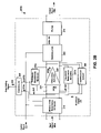
- FIG. 5 is a schematic diagram illustrating a demodulator.
- FIG. 3A is a schematic diagram illustrating one implementation of modulation resistance network 210 .
- Modulation resistance network 210 includes gain-setting resistances 301 a . . . 301 x , 302 a . . . 302 x , and switches 305 a . . . 305 x , 306 a . . . 306 x .
- switches 305 a . . . 305 x , 306 a . . . 306 x are enabled using control signal 241 a which allows signal flow through an associated resistance at a frequency of carrier signal 211 .
- input resistance is substantially defined by a combination resistance of activated gain-setting resistance 301 a and switch 305 a .
- input resistance is substantially defined by a combination resistance of activated gain-setting resistance 301 a and switch 305 a in a parallel configuration with a combination resistance of activated gain-setting resistance 301 b and switch 305 b .
- the parallel configuration advantageously reduces overall input resistance. Enabling of input resistance units is discussed in greater detail below in associated with FIG. 3B .
- control signal 241 b can direct a parallel configuration of input resistances (e.g., in modulation resistance network 210 ) that is cancelled by a series configuration of feedback resistances (e.g., in feedback resistance network 220 a,b ) by generating a feedback resistance value substantially inversely proportional to an input resistance value.
- feedback resistance network 220 d includes feedback resistance 220 b ( FIG. 4B ), and in addition, resistances 454 a . . . 454 x and switches 455 a . . . 455 x .
- Feedback resistance network 220 d has a configuration that mirrors feedback resistance network 220 c of FIG. 4C .
- Feedback resistance network 220 d also has a similar operation to feedback resistance network 220 c.
Abstract
Description
Claims (38)
Priority Applications (1)
| Application Number | Priority Date | Filing Date | Title |
|---|---|---|---|
| US11/115,578 US7295061B1 (en) | 2004-09-02 | 2005-04-26 | Fully integrated programmable gain chopper amplifier with self DC offset suppression |
Applications Claiming Priority (2)
| Application Number | Priority Date | Filing Date | Title |
|---|---|---|---|
| US60674704P | 2004-09-02 | 2004-09-02 | |
| US11/115,578 US7295061B1 (en) | 2004-09-02 | 2005-04-26 | Fully integrated programmable gain chopper amplifier with self DC offset suppression |
Publications (1)
| Publication Number | Publication Date |
|---|---|
| US7295061B1 true US7295061B1 (en) | 2007-11-13 |
Family
ID=38664602
Family Applications (1)
| Application Number | Title | Priority Date | Filing Date |
|---|---|---|---|
| US11/115,578 Active 2025-08-30 US7295061B1 (en) | 2004-09-02 | 2005-04-26 | Fully integrated programmable gain chopper amplifier with self DC offset suppression |
Country Status (1)
| Country | Link |
|---|---|
| US (1) | US7295061B1 (en) |
Cited By (22)
| Publication number | Priority date | Publication date | Assignee | Title |
|---|---|---|---|---|
| US20080180278A1 (en) * | 2007-01-31 | 2008-07-31 | Medtronic, Inc. | Chopper-stabilized instrumentation amplifier for wireless telemetry |
| US20080191800A1 (en) * | 2007-02-09 | 2008-08-14 | Deyou Fang | Dual-chopper amplifier and its usage as readout circuit for capacitive sensors |
| US20080269841A1 (en) * | 2007-04-30 | 2008-10-30 | Medtronic, Inc. | Chopper mixer telemetry circuit |
| EP2128633A1 (en) * | 2008-05-29 | 2009-12-02 | Austriamicrosystems AG | Current-sense amplifier arrangement and method for measuring a voltage signal |
| US20090312664A1 (en) * | 2006-08-03 | 2009-12-17 | Rodriguez Villegas Esther O | Apparatus and method for obtaining eeg data |
| US20100033240A1 (en) * | 2007-01-31 | 2010-02-11 | Medtronic, Inc. | Chopper-stabilized instrumentation amplifier for impedance measurement |
| US20100114223A1 (en) * | 2008-10-31 | 2010-05-06 | Wahlstrand John D | Determining intercardiac impedance |
| US20100327887A1 (en) * | 2007-01-31 | 2010-12-30 | Medtronic, Inc. | Chopper-stabilized instrumentation amplifier for impedance measurement |
| US20110068861A1 (en) * | 2007-01-31 | 2011-03-24 | Medtronic, Inc. | Chopper-stabilized instrumentation amplifier |
| US20110109389A1 (en) * | 2009-09-10 | 2011-05-12 | Federico Alessandro Fabrizio Beffa | Amplifier circuit, integrated circuit and radio frequency communication unit |
| US8099073B1 (en) * | 2007-05-22 | 2012-01-17 | Marvell International Ltd. | Noise reduction in amplifier circuitry using single-sideband chopper stabilization |
| US20120087515A1 (en) * | 2010-10-07 | 2012-04-12 | Research In Motion Limited | Circuit, system and method for isolating a transducer from an amplifier in an electronic device |
| US20140077872A1 (en) * | 2012-09-14 | 2014-03-20 | Ricoh Company, Ltd. | Signal amplification circuit and signal amplification determination circuit including the signal amplification circuit |
| US8829988B2 (en) * | 2012-09-14 | 2014-09-09 | Infineon Technologies Ag | Chopped circuit with AC and DC ripple error feedback loops |
| US8941410B1 (en) * | 2008-07-01 | 2015-01-27 | Cypress Semiconductor Corporation | Programmable buffer circuit |
| US20150116035A1 (en) * | 2013-10-31 | 2015-04-30 | Sanjoy K. Dey | Digital calibration of programmable gain amplifiers |
| US9248288B2 (en) | 2007-09-26 | 2016-02-02 | Medtronic, Inc. | Patient directed therapy control |
| US9924904B2 (en) | 2014-09-02 | 2018-03-27 | Medtronic, Inc. | Power-efficient chopper amplifier |
| US10840866B2 (en) | 2018-03-15 | 2020-11-17 | Tdk Corporation | Amplifier circuit arrangement and method to calibrate the same |
| US11139789B1 (en) | 2020-06-05 | 2021-10-05 | Analog Devices, Inc. | Chopper amplifiers with tracking of multiple input offsets |
| US20210344315A1 (en) * | 2020-05-04 | 2021-11-04 | Infineon Technologies Ag | Chopper system and method |
| US11228291B2 (en) | 2020-05-22 | 2022-01-18 | Analog Devices, Inc. | Chopper amplifiers with multiple sensing points for correcting input offset |
Citations (15)
| Publication number | Priority date | Publication date | Assignee | Title |
|---|---|---|---|---|
| US4331929A (en) | 1979-04-04 | 1982-05-25 | Nippon Gakki Seizo Kabushiki Kaisha | Gain-controlled amplifier |
| US4855685A (en) * | 1987-09-30 | 1989-08-08 | Texas Instruments Incorporated | Precision switchable gain circuit |
| US5097223A (en) | 1990-05-22 | 1992-03-17 | Analog Devices, Inc. | Current feedback audio power amplifier |
| US5351012A (en) | 1993-04-02 | 1994-09-27 | Elantec, Inc. | Low input resistance current-mode feedback operational amplifier input stage |
| US6262626B1 (en) * | 1998-11-12 | 2001-07-17 | U.S. Philips Corporation | Circuit comprising means for reducing the DC-offset and the noise produced by an amplifier |
| US6307430B1 (en) | 2000-10-02 | 2001-10-23 | Cirrus Logic, Inc. | Noise reduction technique in chopper stabilized amplifier |
| US6316998B1 (en) | 1997-11-12 | 2001-11-13 | Nec Corporation | Differential amplifier and a method of compensation |
| US6429735B1 (en) | 2001-08-29 | 2002-08-06 | National Semiconductor Corporation | High speed output buffer |
| US20020171474A1 (en) | 2001-05-18 | 2002-11-21 | Alcatel | Offset control of an operational amplifier |
| US6492871B2 (en) | 2000-12-29 | 2002-12-10 | Silicon Integrated Systems Corp. | Current feedback operational amplifier |
| US6636116B2 (en) | 2001-10-05 | 2003-10-21 | Texas Instruments Incorporated | Fully differential current feedback amplifier |
| US6724248B2 (en) | 2001-04-24 | 2004-04-20 | Tripath Technology, Inc. | DC offset self-calibration system for a digital switching amplifier |
| US6734723B2 (en) | 2002-04-05 | 2004-05-11 | Maxim Integrated Products, Inc. | Chopper chopper-stabilized operational amplifiers and methods |
| US6768374B1 (en) * | 2002-10-03 | 2004-07-27 | National Semiconductor Corporation | Programmable gain amplifier with single stage switched capacitor circuit using bandwidth balancing |
| US7215198B1 (en) | 2004-06-01 | 2007-05-08 | Marvell International Ltd. | Fully differential current-feedback CMOS/bipolar operational amplifier |
-
2005
- 2005-04-26 US US11/115,578 patent/US7295061B1/en active Active
Patent Citations (15)
| Publication number | Priority date | Publication date | Assignee | Title |
|---|---|---|---|---|
| US4331929A (en) | 1979-04-04 | 1982-05-25 | Nippon Gakki Seizo Kabushiki Kaisha | Gain-controlled amplifier |
| US4855685A (en) * | 1987-09-30 | 1989-08-08 | Texas Instruments Incorporated | Precision switchable gain circuit |
| US5097223A (en) | 1990-05-22 | 1992-03-17 | Analog Devices, Inc. | Current feedback audio power amplifier |
| US5351012A (en) | 1993-04-02 | 1994-09-27 | Elantec, Inc. | Low input resistance current-mode feedback operational amplifier input stage |
| US6316998B1 (en) | 1997-11-12 | 2001-11-13 | Nec Corporation | Differential amplifier and a method of compensation |
| US6262626B1 (en) * | 1998-11-12 | 2001-07-17 | U.S. Philips Corporation | Circuit comprising means for reducing the DC-offset and the noise produced by an amplifier |
| US6307430B1 (en) | 2000-10-02 | 2001-10-23 | Cirrus Logic, Inc. | Noise reduction technique in chopper stabilized amplifier |
| US6492871B2 (en) | 2000-12-29 | 2002-12-10 | Silicon Integrated Systems Corp. | Current feedback operational amplifier |
| US6724248B2 (en) | 2001-04-24 | 2004-04-20 | Tripath Technology, Inc. | DC offset self-calibration system for a digital switching amplifier |
| US20020171474A1 (en) | 2001-05-18 | 2002-11-21 | Alcatel | Offset control of an operational amplifier |
| US6429735B1 (en) | 2001-08-29 | 2002-08-06 | National Semiconductor Corporation | High speed output buffer |
| US6636116B2 (en) | 2001-10-05 | 2003-10-21 | Texas Instruments Incorporated | Fully differential current feedback amplifier |
| US6734723B2 (en) | 2002-04-05 | 2004-05-11 | Maxim Integrated Products, Inc. | Chopper chopper-stabilized operational amplifiers and methods |
| US6768374B1 (en) * | 2002-10-03 | 2004-07-27 | National Semiconductor Corporation | Programmable gain amplifier with single stage switched capacitor circuit using bandwidth balancing |
| US7215198B1 (en) | 2004-06-01 | 2007-05-08 | Marvell International Ltd. | Fully differential current-feedback CMOS/bipolar operational amplifier |
Non-Patent Citations (8)
| Title |
|---|
| AD8001, 800 MHz, 50 mW Current Feedback Amplifier, Analog Devices, Inc. Specification Sheet, Rev. D, 2003. |
| EL2120, 100MHz Current Feedback Amplifier, Intersil(R) Data Sheet, Jan. 1996, Rev. E. |
| Mahmoud, Soliman Awad, Low Voltage Analog VLSI Circuits, Cairo University-Theses; Electronics and Communications Department; Theses Registration Mar. 15, 1997 (Summary Only). |
| Office Action dated Jan. 20, 2006 from related case US Patent Number 7215198. |
| Office Action dated Jul. 24, 2006 from related case US Patent Number 7215198. |
| Office Action dated May 10, 2006 from related case US Patent Number 7215198. |
| OPA684, Low-Power, Current Feedback Operational Amplifier With Disable, Texas Instruments Incorporated, SBOS219A-Mar. 2002. |
| Schmid, Hanspeter, The Current-Feedback OTA, IEEE, Sep. 2001. |
Cited By (39)
| Publication number | Priority date | Publication date | Assignee | Title |
|---|---|---|---|---|
| US20090312664A1 (en) * | 2006-08-03 | 2009-12-17 | Rodriguez Villegas Esther O | Apparatus and method for obtaining eeg data |
| US20080180278A1 (en) * | 2007-01-31 | 2008-07-31 | Medtronic, Inc. | Chopper-stabilized instrumentation amplifier for wireless telemetry |
| US8265769B2 (en) | 2007-01-31 | 2012-09-11 | Medtronic, Inc. | Chopper-stabilized instrumentation amplifier for wireless telemetry |
| US9197173B2 (en) * | 2007-01-31 | 2015-11-24 | Medtronic, Inc. | Chopper-stabilized instrumentation amplifier for impedance measurement |
| US9615744B2 (en) * | 2007-01-31 | 2017-04-11 | Medtronic, Inc. | Chopper-stabilized instrumentation amplifier for impedance measurement |
| US8354881B2 (en) | 2007-01-31 | 2013-01-15 | Medtronic, Inc. | Chopper-stabilized instrumentation amplifier |
| US20100033240A1 (en) * | 2007-01-31 | 2010-02-11 | Medtronic, Inc. | Chopper-stabilized instrumentation amplifier for impedance measurement |
| US20110068861A1 (en) * | 2007-01-31 | 2011-03-24 | Medtronic, Inc. | Chopper-stabilized instrumentation amplifier |
| US20100327887A1 (en) * | 2007-01-31 | 2010-12-30 | Medtronic, Inc. | Chopper-stabilized instrumentation amplifier for impedance measurement |
| US20080191800A1 (en) * | 2007-02-09 | 2008-08-14 | Deyou Fang | Dual-chopper amplifier and its usage as readout circuit for capacitive sensors |
| US7456684B2 (en) * | 2007-02-09 | 2008-11-25 | University Of Florida Research Foundation, Inc. | Dual-chopper amplifier and its usage as readout circuit for capacitive sensors |
| US20080269841A1 (en) * | 2007-04-30 | 2008-10-30 | Medtronic, Inc. | Chopper mixer telemetry circuit |
| US9449501B2 (en) | 2007-04-30 | 2016-09-20 | Medtronics, Inc. | Chopper mixer telemetry circuit |
| US8781595B2 (en) | 2007-04-30 | 2014-07-15 | Medtronic, Inc. | Chopper mixer telemetry circuit |
| US8099073B1 (en) * | 2007-05-22 | 2012-01-17 | Marvell International Ltd. | Noise reduction in amplifier circuitry using single-sideband chopper stabilization |
| US9248288B2 (en) | 2007-09-26 | 2016-02-02 | Medtronic, Inc. | Patient directed therapy control |
| US10258798B2 (en) | 2007-09-26 | 2019-04-16 | Medtronic, Inc. | Patient directed therapy control |
| EP2128633A1 (en) * | 2008-05-29 | 2009-12-02 | Austriamicrosystems AG | Current-sense amplifier arrangement and method for measuring a voltage signal |
| US8941410B1 (en) * | 2008-07-01 | 2015-01-27 | Cypress Semiconductor Corporation | Programmable buffer circuit |
| US20100114223A1 (en) * | 2008-10-31 | 2010-05-06 | Wahlstrand John D | Determining intercardiac impedance |
| US8478402B2 (en) | 2008-10-31 | 2013-07-02 | Medtronic, Inc. | Determining intercardiac impedance |
| US20110109389A1 (en) * | 2009-09-10 | 2011-05-12 | Federico Alessandro Fabrizio Beffa | Amplifier circuit, integrated circuit and radio frequency communication unit |
| US7952430B1 (en) * | 2009-09-10 | 2011-05-31 | Mediatek Singapore Pte. Ltd. | Amplifier circuit, integrated circuit and radio frequency communication unit |
| US20120087515A1 (en) * | 2010-10-07 | 2012-04-12 | Research In Motion Limited | Circuit, system and method for isolating a transducer from an amplifier in an electronic device |
| US8976981B2 (en) * | 2010-10-07 | 2015-03-10 | Blackberry Limited | Circuit, system and method for isolating a transducer from an amplifier in an electronic device |
| CN103684290A (en) * | 2012-09-14 | 2014-03-26 | 株式会社理光 | Signal amplification circuit and signal amplification determination circuit including signal amplification circuit |
| US20140077872A1 (en) * | 2012-09-14 | 2014-03-20 | Ricoh Company, Ltd. | Signal amplification circuit and signal amplification determination circuit including the signal amplification circuit |
| US9203363B2 (en) | 2012-09-14 | 2015-12-01 | Infineon Technologies Ag | Chopped circuit with AC and DC ripple error feedback loops |
| US9071208B2 (en) * | 2012-09-14 | 2015-06-30 | Ricoh Company, Ltd. | Signal amplification circuit and signal amplification determination circuit including the signal amplification circuit |
| US8829988B2 (en) * | 2012-09-14 | 2014-09-09 | Infineon Technologies Ag | Chopped circuit with AC and DC ripple error feedback loops |
| CN103684290B (en) * | 2012-09-14 | 2017-06-09 | 株式会社理光 | Signal amplification circuit and the signal including signal amplification circuit amplify determination circuit |
| US20150116035A1 (en) * | 2013-10-31 | 2015-04-30 | Sanjoy K. Dey | Digital calibration of programmable gain amplifiers |
| US9112465B2 (en) * | 2013-10-31 | 2015-08-18 | Freescale Semiconductor, Inc. | Digital calibration of programmable gain amplifiers |
| US9924904B2 (en) | 2014-09-02 | 2018-03-27 | Medtronic, Inc. | Power-efficient chopper amplifier |
| US10840866B2 (en) | 2018-03-15 | 2020-11-17 | Tdk Corporation | Amplifier circuit arrangement and method to calibrate the same |
| US20210344315A1 (en) * | 2020-05-04 | 2021-11-04 | Infineon Technologies Ag | Chopper system and method |
| US11863137B2 (en) * | 2020-05-04 | 2024-01-02 | Infineon Technologies Ag | Chopper system and method |
| US11228291B2 (en) | 2020-05-22 | 2022-01-18 | Analog Devices, Inc. | Chopper amplifiers with multiple sensing points for correcting input offset |
| US11139789B1 (en) | 2020-06-05 | 2021-10-05 | Analog Devices, Inc. | Chopper amplifiers with tracking of multiple input offsets |
Similar Documents
| Publication | Publication Date | Title |
|---|---|---|
| US7295061B1 (en) | Fully integrated programmable gain chopper amplifier with self DC offset suppression | |
| US5613233A (en) | Apparatus with distortion cancelling feedback signal | |
| US10673389B2 (en) | Chopper amplifiers with high pass filter for suppressing chopping ripple | |
| JP3174340B2 (en) | Automatic gain control device for receiver | |
| US6166668A (en) | Method and apparatus for providing DC offset correction and hold capability | |
| US20090167439A1 (en) | Amplifier and the method thereof | |
| US6861896B2 (en) | Circuits with dynamic biasing | |
| US9685914B2 (en) | Amplifier circuit | |
| WO2018140609A1 (en) | Bias modulation active linearization for broadband amplifiers | |
| US6750703B1 (en) | DC offset canceling circuit applied in a variable gain amplifier | |
| JP2009071608A (en) | Offset cancellation circuit and differential amplifier circuit | |
| JP2001119269A (en) | 90-degree phase shifter | |
| EP3734837A1 (en) | Gain stage with offset cancellation circuit for a fixed high-pass pole | |
| JPH0683113B2 (en) | Line equalization circuit | |
| CN116032283B (en) | Programmable gain amplifying circuit with DCOC calibration and implementation method | |
| EP1213724A1 (en) | Process-insensitive, highly-linear constant transconductance circuit | |
| JP2834000B2 (en) | Intermediate frequency amplifier circuit | |
| US6741131B2 (en) | DC-compensation loop for variable gain amplifier | |
| GB2400997A (en) | A CMOS differential amplifier with a common-mode feedback circuit acting on the output nodes. | |
| JP3462408B2 (en) | DC feedback circuit | |
| JP3804631B2 (en) | Amplification equipment | |
| JP2005333651A (en) | Amplifier arrangement and method for compensation of signal component in amplifier arrangement | |
| JP2004274434A (en) | Video signal correction circuit | |
| KR20040008819A (en) | Receiver of communication system having offset voltage compensation circuit | |
| JP3041871B2 (en) | Signal correction circuit |
Legal Events
| Date | Code | Title | Description |
|---|---|---|---|
| AS | Assignment |
Owner name: MARVELL ASIA PTE, LTD., SINGAPORE Free format text: ASSIGNMENT OF ASSIGNORS INTEREST;ASSIGNOR:DASGUPTA, UDAY;REEL/FRAME:016519/0885 Effective date: 20050426 |
|
| AS | Assignment |
Owner name: MARVELL INTERNATIONAL LTD., BERMUDA Free format text: ASSIGNMENT OF ASSIGNORS INTEREST;ASSIGNOR:MARVELL ASIA PTE. LTD.;REEL/FRAME:016667/0866 Effective date: 20050817 |
|
| STCF | Information on status: patent grant |
Free format text: PATENTED CASE |
|
| FPAY | Fee payment |
Year of fee payment: 4 |
|
| FPAY | Fee payment |
Year of fee payment: 8 |
|
| MAFP | Maintenance fee payment |
Free format text: PAYMENT OF MAINTENANCE FEE, 12TH YEAR, LARGE ENTITY (ORIGINAL EVENT CODE: M1553); ENTITY STATUS OF PATENT OWNER: LARGE ENTITY Year of fee payment: 12 |
|
| AS | Assignment |
Owner name: CAVIUM INTERNATIONAL, CAYMAN ISLANDS Free format text: ASSIGNMENT OF ASSIGNORS INTEREST;ASSIGNOR:MARVELL INTERNATIONAL LTD.;REEL/FRAME:052918/0001 Effective date: 20191231 |
|
| AS | Assignment |
Owner name: MARVELL ASIA PTE, LTD., SINGAPORE Free format text: ASSIGNMENT OF ASSIGNORS INTEREST;ASSIGNOR:CAVIUM INTERNATIONAL;REEL/FRAME:053475/0001 Effective date: 20191231 |