US7278759B2 - Slave strobe - Google Patents
Slave strobe Download PDFInfo
- Publication number
- US7278759B2 US7278759B2 US11/264,062 US26406205A US7278759B2 US 7278759 B2 US7278759 B2 US 7278759B2 US 26406205 A US26406205 A US 26406205A US 7278759 B2 US7278759 B2 US 7278759B2
- Authority
- US
- United States
- Prior art keywords
- strobe
- flash
- light
- slave strobe
- recited
- Prior art date
- Legal status (The legal status is an assumption and is not a legal conclusion. Google has not performed a legal analysis and makes no representation as to the accuracy of the status listed.)
- Expired - Fee Related, expires
Links
Images


Classifications
-
- G—PHYSICS
- G03—PHOTOGRAPHY; CINEMATOGRAPHY; ANALOGOUS TECHNIQUES USING WAVES OTHER THAN OPTICAL WAVES; ELECTROGRAPHY; HOLOGRAPHY
- G03B—APPARATUS OR ARRANGEMENTS FOR TAKING PHOTOGRAPHS OR FOR PROJECTING OR VIEWING THEM; APPARATUS OR ARRANGEMENTS EMPLOYING ANALOGOUS TECHNIQUES USING WAVES OTHER THAN OPTICAL WAVES; ACCESSORIES THEREFOR
- G03B15/00—Special procedures for taking photographs; Apparatus therefor
- G03B15/02—Illuminating scene
- G03B15/03—Combinations of cameras with lighting apparatus; Flash units
- G03B15/05—Combinations of cameras with electronic flash apparatus; Electronic flash units
-
- G—PHYSICS
- G03—PHOTOGRAPHY; CINEMATOGRAPHY; ANALOGOUS TECHNIQUES USING WAVES OTHER THAN OPTICAL WAVES; ELECTROGRAPHY; HOLOGRAPHY
- G03B—APPARATUS OR ARRANGEMENTS FOR TAKING PHOTOGRAPHS OR FOR PROJECTING OR VIEWING THEM; APPARATUS OR ARRANGEMENTS EMPLOYING ANALOGOUS TECHNIQUES USING WAVES OTHER THAN OPTICAL WAVES; ACCESSORIES THEREFOR
- G03B2215/00—Special procedures for taking photographs; Apparatus therefor
- G03B2215/05—Combinations of cameras with electronic flash units
- G03B2215/0514—Separate unit
- G03B2215/0517—Housing
- G03B2215/0525—Reflector
- G03B2215/0528—Reflector movable reflector, e.g. change of illumination angle or illumination direction
-
- G—PHYSICS
- G03—PHOTOGRAPHY; CINEMATOGRAPHY; ANALOGOUS TECHNIQUES USING WAVES OTHER THAN OPTICAL WAVES; ELECTROGRAPHY; HOLOGRAPHY
- G03B—APPARATUS OR ARRANGEMENTS FOR TAKING PHOTOGRAPHS OR FOR PROJECTING OR VIEWING THEM; APPARATUS OR ARRANGEMENTS EMPLOYING ANALOGOUS TECHNIQUES USING WAVES OTHER THAN OPTICAL WAVES; ACCESSORIES THEREFOR
- G03B2215/00—Special procedures for taking photographs; Apparatus therefor
- G03B2215/05—Combinations of cameras with electronic flash units
- G03B2215/0514—Separate unit
- G03B2215/0557—Multiple units, e.g. slave-unit
Definitions
- slave strobes There are two types of traditional slave strobes. One is hard-wired (or controlled wirelessly in some examples) to the master device (usually a camera) and fires its strobe when the master signals it to do so. In this configuration, it could be controlled to fire multiple times and could even be told to fire for a particular length of time depending on the control signals received from the master device.
- One disadvantage for this type of slave strobe is that the master and the slave must be designed to work together, since they both must use the same set of control signals. This limits a family of slave strobes to a particular family of master devices that use the same control signals.
- the other traditional slave strobe is one that “looks” for a short pulse of light that is significantly brighter than the ambient light. These slaves fire when they detect a strobe fire from a master device or even from a secondary slave device. This type of slave strobe is very convenient as it does not require a camera with a strobe output (many of the newer pocket cameras do not include a strobe output).
- slave strobes are limited in their ability to operate in differing power modes, delay modes, and other modes of operation.
- a slave strobe will have a slide switch allowing a user to change power modes, however, these switches are typically small and fragile.
- a slave strobe will have a set angle covered by the flash, and are unable to focus a flash for distant objects. If a user desires to change the color of a slave strobe, most strobes require a filter accessory to be placed in front of the flash tube containing a color filter. Alternatively, some of these strobe filter accessories have had the ability to contain fresnel lenses, and thus change the focus of the flash. However, such accessories are cumbersome, easy to lose or forget, and susceptible to damage.
- a slave strobe is built including a photodetector, a flash tube, a flash controller, a mode switch, a body, and a top rotatable with respect to the body, and depressible with respect to the body.
- the photodetector is configured to detect a flash of light.
- the flash controller is electrically coupled with the photodetector, the mode switch and the flash tube, and is configured to change modes of operation when the mode switch is activated.
- the mode switch is configured to activate when the top is depressed.
- the top includes a plurality of strobe lenses configured to modify a flash of light from the flash tube when rotated in front of the flash tube.
- FIG. 1A is a top view of a slave strobe according to an example embodiment of the present invention.
- FIG. 1B is a bottom view of the slave strobe from FIG. 1A according to an example embodiment of the present invention.
- FIG. 1C is a front view of the slave strobe from FIG. 1A according to an example embodiment of the present invention.
- FIG. 1D is a rear view of the slave strobe from FIG. 1A according to an example embodiment of the present invention.
- FIG. 1E is a left view of the slave strobe from FIG. 1A according to an example embodiment of the present invention.
- FIG. 1F is a right view of the slave strobe from FIG. 1A according to an example embodiment of the present invention.
- FIG. 2A is an upper left perspective view of the slave strobe from FIGS. 1A-1F according to an example embodiment of the present invention.
- FIG. 2B is an upper right perspective view of the slave strobe from FIGS. 1A-1F according to an example embodiment of the present invention.
- FIG. 2C is a lower left perspective view of the slave strobe from FIGS. 1A-1F according to an example embodiment of the present invention.
- FIG. 2D is a lower right perspective view of the slave strobe from FIGS. 1A-1F according to an example embodiment of the present invention.
- FIG. 3 is a front view exploded parts diagram of the slave strobe from FIGS. 1A-1F according to an example embodiment of the present invention.
- FIG. 4 is a side view exploded parts diagram of the slave strobe from FIGS. 1A-1F according to an example embodiment of the present invention.
- FIG. 5 is a top view exploded parts diagram of the slave strobe from FIGS. 1A-1F according to an example embodiment of the present invention.
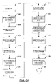
- FIG. 6A is a first part of a flowchart of an example embodiment of a method of manufacturing a slave strobe according to the present invention.
- FIG. 6B is a second part of a flowchart of an example embodiment of a method of manufacturing a slave strobe according to the present invention.
- FIG. 1A is a top view of a slave strobe according to an example embodiment of the present invention.
- a slave strobe is constructed including a body 106 , and a top 112 rotatably coupled with the body.
- a photodetector 101 such as a photodiode
- a photodetector diffuser 100 configured to measure ambient light
- a pusher 102 configured to activate a mode switch 126 when the top 112 is pushed towards the body 106
- at least one strobe lens 108 , 116 , and 118 are examples of the top 112 .
- strobe lenses 108 , 116 , and 118 While this example embodiment of the present invention includes three strobe lenses 108 , 116 , and 118 , those of skill in the art will recognize that any number of strobe lenses 108 , 116 , and 118 may be provided within the scope of the present invention.
- a focusing lens 108 is used to focus the light of the flash tube 125
- a diffusing lens 116 is used to spread the light of the flash tube 125
- a filtering lens 118 is used to filter the light of the flash tube 125 .
- special effects lenses such as lenses that split the light from the flash tube 125 to focus the light in two or more different locations, polarizing lenses, neutral density lenses, and any imaginable lenses usable for modifying the light from the flash tube 125 may be used within the scope of the present invention.
- the top 112 is rotatable with respect to the body 106 it may be rotated to position one of the strobe lenses 108 , 116 , and 118 in front of the flash tube 125 . This allows the user to select from the available strobe lenses 108 , 116 , and 118 to modify the light from the flash tube 125 and to rotate the appropriate lens in front of the flash tube 125 while the flash tube 125 remains in a fixed location with respect to the body 106 .
- one of the strobe lenses 108 , 116 , and 118 may be transparent allowing the flash tube 125 to illuminate the scene with unmodified and unfiltered light.
- FIG. 1B is a bottom view of the slave strobe from FIG. 1A according to an example embodiment of the present invention.
- the example embodiment of a slave strobe shown in these figures also includes an optional base 104 mechanically coupled to the body 106 of the slave strobe, such that the body 106 is able to tilt with respect to the base 104 . This allows the light from the slave strobe to be aimed.
- the base in this example embodiment 104 also includes a tripod mount 114 , and at least one magnet 114 , both of which are optional.
- Those of skill in the art will recognize that some embodiments of the present invention may not require the base 104 at all, while others may use a base 104 with or without the tripod mount 110 , and any number of magnets 114 . If magnets 114 are included in the base 104 , the slave strobe will be able to be magnetically affixed to some metal surfaces, allowing the positioning and holding of the slave strobe without the use of a tripod.
- FIG. 1C is a front view of the slave strobe from FIG. 1A according to an example embodiment of the present invention.
- the focusing lens 108 is facing forward and is currently in front of the strobe tube 125 thus the light from the strobe tube 125 will be focused.
- the body 106 is in a vertical position with respect to the base 104 , however it is configured to rotate forwards or backwards with respect to the base 104 .
- FIG. 1D is a rear view of the slave strobe from FIG. 1A according to an example embodiment of the present invention.
- FIG. 1E is a left view of the slave strobe from FIG. 1A according to an example embodiment of the present invention.
- FIG. IF is a right view of the slave strobe from FIG. 1A according to an example embodiment of the present invention.
- FIG. 2A is an upper left perspective view of the slave strobe from FIGS. 1A-1F according to an example embodiment of the present invention.
- FIG. 2B is an upper right perspective view of the slave strobe from FIGS. 1A-1F according to an example embodiment of the present invention.
- FIG. 2C is a lower left perspective view of the slave strobe from FIGS. 1A-1F according to an example embodiment of the present invention.
- FIG. 2D is a lower right perspective view of the slave strobe from FIGS. 1A-1F according to an example embodiment of the present invention.
- FIG. 3 is a front view exploded parts diagram of the slave strobe from FIGS. 1A-1F according to an example embodiment of the present invention.
- the strobe tube body 106 is rotatably coupled with a cap 144 , where a contact positioner 140 and lower battery contacts 138 are positioned within the cap 144 .
- the cap 144 also includes a reed switch magnet 142 configured to operate a reed switch 134 mechanically coupled with a battery holder 132 .
- the contact positioner 140 moves vertically within a slot in the body 106 but is prevented from rotating with the cap 144 .
- the cap 144 rotates as it is assembled to the body 106 without the flash assembly rotating within the body 106 and the contact positioner 140 moves vertically to provide adequate contact with the batteries contained in the battery holder 132 .
- the reed switch magnet 142 activates the reed switch 134 and turns on the slave strobe.
- the cap 144 is rotated in the reverse direction, moving the reed switch magnet 142 away from the reed switch 134 , deactivating the reed switch 134 and turning off the slave strobe.
- the body 106 is mechanically coupled with the base 104 by a pair of pins 146 .
- the fit between the body 106 and the base 104 preferably is such that the body 106 may tilt with respect to the base 104 , but will hold its tilted position when released.
- Some embodiments of the present invention may use friction between the body 106 and the base 104 to allow the slave strobe to hold its position.
- the flash tube 125 is assembled with a reflector head 124 , and this resulting assembly is mechanically coupled with the body 106 and electrically coupled with the flash controller 128 .
- a mode switch 126 is electrically and mechanically coupled with the flash controller 128 along with a strobe capacitor 130 .
- the flash controller 128 is also electrically coupled with a battery holder 132 including upper battery contacts 136 .
- the flash controller 128 , strobe capacitor 130 , and battery holder 132 are all positioned within the body 106 of the slave strobe.
- the reflector head 124 including the flash head 125 are positioned within the top 112 of the slave strobe.
- a spring washer 122 is configured to exert upward pressure against the top 112 , pushing it up away from the body 106 .
- the spring washer 122 When the top 112 is pressed towards the body 106 , the spring washer 122 is compressed.
- the pusher 102 which is mechanically coupled with the top 112 is configured so that when the top 112 is pressed towards the body 106 the pusher 102 activates the mode switch 126 .
- This mode switch 126 which is electrically coupled with the flash controller 128 then changes a mode of the slave strobe.
- the mode switch 126 may be configured to cycle through a set of slave strobe power modes, such as half-power and quarter-power.
- the mode switch 126 may be configured to cycle through a set of slave strobe delay times all within the scope of the present invention.
- a plurality of set screws 120 are used to mechanically couple the top 112 with the body 106 of the slave strobe such that the top 112 may rotate with respect to the body 106 to change which strobe lens 108 , 116 , and 118 is positioned in front of the flash tube 125 .
- the top 112 is also coupled to the body 106 such that it may be depressed in order to activate the mode switch 126 .
- any mechanical configuration allowing the top 112 to rotate and be depressed with respect to the body 106 may be used within the scope of the present invention.
- the flash controller 128 also includes at least one mode light 127 configured to shine through the transparent pusher 102 such that the pusher 102 effectively acts as a light pipe to allow the user to see the status of the mode light 127 reflecting the mode of operation of the slave strobe through the top 112 of the slave strobe.
- These mode lights 127 may be lit, flashing, or unlit to indicate the current mode of operation of the slave strobe. As the user cycles through the configured modes of operation by pressing the top 112 the mode lights 127 change status to visibly reflect the current mode of operation.
- the mode lights 127 are light emitting diodes (LEDs.)
- FIG. 4 is a side view exploded parts diagram of the slave strobe from FIGS. 1A-1F according to an example embodiment of the present invention.
- FIG. 5 is a top view exploded parts diagram of the slave strobe from FIGS. 1A-1F according to an example embodiment of the present invention.
- Photodetector Diffuser 101 Photodetector 102 Pusher 104 Base 106 Body 108 Focusing Lens 110 Tripod Mount 112 Top 114 Magnet 116 Diffusing Lens 118 Filtering Lens 120 Set Screws 122 Spring Washer 124 Reflector Head 125 Flash Tube 126 Mode Switch 127 Mode Lights 128 Flash Controller 130 Strobe Capacitor 132 Battery Holder 134 Reed Switch 136 Upper Battery Contacts 138 Lower Battery Contacts 140 Contact Positioner 142 Reed Switch Magnet 144 Cap 146 Pins 148 Reflector
- FIG. 6A is a first part of a flowchart of an example embodiment of a method of manufacturing a slave strobe according to the present invention.
- a body is provided.
- a top is mechanically coupled to the body such that the top may rotate and be depressed with respect to the body.
- a flash tube is mechanically coupled to the body.
- a flash controller is mechanically coupled to the body.
- a mode switch is electrically coupled to the flash controller.
- the mode switch is configured to change a mode of operation of the slave strobe when it is activated.
- a pusher is mechanically. coupled to the top.
- the pusher is configured to activate the mode switch when the top is depressed.
- a plurality of strobe lenses are mechanically coupled to the top.
- each strobe lens is configured to modify a flash of light from the flash tube when the lens is rotated in front of the flash tube.
- the flash controller is electrically coupled to a photodetector and the flash tube.
- the photodetector is configured to measure ambient light.
- the flash controller is configured to detect a flash of light seen by the photodetector.
- the flow chart is continued in FIG. 6B .
- FIG. 6B is a second part of a flowchart of an example embodiment of a method of manufacturing a slave strobe according to the present invention.
- the flash controller is configured to fire the flash tube after a flash of light is detected.
- at least one mode light is electrically coupled with the flash controller.
- the mode light is configured to signal a mode of operation.
- the pusher is configured to act as a light pipe allowing light from the mode light to be visible on the top.
- a cap is mechanically coupled with the body such that the cap may rotate with respect to the body.
- a reed switch is mechanically coupled with the body.
- the reed switch is electrically coupled with the flash controller.
- the reed switch is configured to turn on the slave strobe when it is activated.
- a reed switch magnet is mechanically coupled with the cap.
- the reed switch magnet is configured to activate the reed switch when the cap is rotated with respect to the body.
Abstract
A slave strobe is built including a photodetector, a flash tube, a flash controller, a mode switch, a body, and a top rotatable with respect to the body, and depressible with respect to the body. The photodetector is configured to detect a flash of light. The flash controller is electrically coupled with the photodetector, the mode switch and the flash tube, and is configured to change modes of operation when the mode switch is activated. The mode switch is configured to activate when the top is depressed. The top includes a plurality of strobe lenses configured to modify a flash of light from the flash tube when rotated in front of the flash tube.
Description
There are two types of traditional slave strobes. One is hard-wired (or controlled wirelessly in some examples) to the master device (usually a camera) and fires its strobe when the master signals it to do so. In this configuration, it could be controlled to fire multiple times and could even be told to fire for a particular length of time depending on the control signals received from the master device. One disadvantage for this type of slave strobe is that the master and the slave must be designed to work together, since they both must use the same set of control signals. This limits a family of slave strobes to a particular family of master devices that use the same control signals.
The other traditional slave strobe is one that “looks” for a short pulse of light that is significantly brighter than the ambient light. These slaves fire when they detect a strobe fire from a master device or even from a secondary slave device. This type of slave strobe is very convenient as it does not require a camera with a strobe output (many of the newer pocket cameras do not include a strobe output).
Many slave strobes are limited in their ability to operate in differing power modes, delay modes, and other modes of operation. Typically, a slave strobe will have a slide switch allowing a user to change power modes, however, these switches are typically small and fragile.
Often a slave strobe will have a set angle covered by the flash, and are unable to focus a flash for distant objects. If a user desires to change the color of a slave strobe, most strobes require a filter accessory to be placed in front of the flash tube containing a color filter. Alternatively, some of these strobe filter accessories have had the ability to contain fresnel lenses, and thus change the focus of the flash. However, such accessories are cumbersome, easy to lose or forget, and susceptible to damage.
A slave strobe is built including a photodetector, a flash tube, a flash controller, a mode switch, a body, and a top rotatable with respect to the body, and depressible with respect to the body. The photodetector is configured to detect a flash of light. The flash controller is electrically coupled with the photodetector, the mode switch and the flash tube, and is configured to change modes of operation when the mode switch is activated. The mode switch is configured to activate when the top is depressed. The top includes a plurality of strobe lenses configured to modify a flash of light from the flash tube when rotated in front of the flash tube.
Other aspects and advantages of the present invention will become apparent from the following detailed description, taken in conjunction with the accompanying drawings, illustrating by way of example the principles of the invention.
This description of the preferred embodiments is intended to be read in connection with the accompanying drawings, which are to be considered part of the entire written description of this invention. In the description, relative terms such as “lower,” “upper,” “horizontal,” “vertical,” “up,” “down,” “top,” “bottom,” “left,” and “right” as well as derivatives thereof (e.g., “horizontally,” “downwardly,” “upwardly,” etc.) should be construed to refer to the orientation as then described or as shown in the drawing figure under discussion. These relative terms are for convenience of description and normally are not intended to require a particular orientation. Terms concerning attachments, coupling and the like, such as “connected,” “coupled,” and “interconnected,” refer to a relationship wherein structures are secured or attached to one another either directly or indirectly through intervening structures, as well as both movable or rigid attachments or relationships, unless expressly described otherwise.
In this example embodiment of the present invention a focusing lens 108 is used to focus the light of the flash tube 125, a diffusing lens 116 is used to spread the light of the flash tube 125, and a filtering lens 118 is used to filter the light of the flash tube 125. Those of skill in the art will recognize that these three examples of strobe lenses 108, 116, and 118, are not a complete set of the possible strobe lenses within the scope of the present invention. For example, special effects lenses, such as lenses that split the light from the flash tube 125 to focus the light in two or more different locations, polarizing lenses, neutral density lenses, and any imaginable lenses usable for modifying the light from the flash tube 125 may be used within the scope of the present invention. Since the top 112 is rotatable with respect to the body 106 it may be rotated to position one of the strobe lenses 108, 116, and 118 in front of the flash tube 125. This allows the user to select from the available strobe lenses 108, 116, and 118 to modify the light from the flash tube 125 and to rotate the appropriate lens in front of the flash tube 125 while the flash tube 125 remains in a fixed location with respect to the body 106. In some example embodiments of the present invention one of the strobe lenses 108, 116, and 118 may be transparent allowing the flash tube 125 to illuminate the scene with unmodified and unfiltered light.
FIG. IF is a right view of the slave strobe from FIG. 1A according to an example embodiment of the present invention.
| |
| 100 | |
||
| 101 | |
||
| 102 | |
||
| 104 | |
||
| 106 | |
||
| 108 | Focusing |
||
| 110 | |
||
| 112 | |
||
| 114 | |
||
| 116 | |
||
| 118 | |
||
| 120 | |
||
| 122 | |
||
| 124 | |
||
| 125 | |
||
| 126 | |
||
| 127 | |
||
| 128 | |
||
| 130 | |
||
| 132 | |
||
| 134 | |
||
| 136 | |
||
| 138 | |
||
| 140 | |
||
| 142 | |
||
| 144 | |
||
| 146 | |
||
| 148 | Reflector | ||
The foregoing description of the present invention has been presented for purposes of illustration and description. It is not intended to be exhaustive or to limit the invention to the precise form disclosed, and other modifications and variations may be possible in light of the above teachings. The embodiments were chosen and described in order to best explain the principles of the invention and its practical application to thereby enable others skilled in the art to best utilize the invention in various embodiments and various modifications as are suited to the particular use contemplated. It is intended that the appended claims be construed to include other alternative embodiments of the invention except insofar as limited by the prior art.
Claims (16)
1. A slave strobe comprising:
a body;
a top mechanically coupled to said body such that said top may rotate and be depressed with respect to said body;
a flash tube;
a flash controller configured to control said flash tube;
a mode switch electrically coupled with said flash controller and configured to change a mode of operation when activated;
a pusher mechanically coupled with said top, configured to activate said mode switch when said top is depressed;
a plurality of strobe lenses mechanically coupled with said top, configured to modify a flash of light from said flash tube when rotated in front of said flash tube;
a photodetector electrically coupled with said flash controller, configured to measure ambient light, and detect a flash of light;
at least one mode light, electrically coupled with said flash controller, and configured to signal a mode of operation, and
wherein said pusher is configured to act as a light pipe allowing light from said mode light to be visible on said top.
2. The slave strobe recited in claim 1 ,
wherein one of said strobe lenses is a focusing lens.
3. The slave strobe recited in claim 1 ,
wherein one of said strobe lenses is a filtering lens.
4. The slave strobe recited in claim 1 ,
wherein one of said strobe lenses is a diffusing lens.
5. The slave strobe recited in claim 1 , further comprising:
a base, mechanically coupled with said body, and configured to allow said body to tilt with respect to said base.
6. The slave strobe recited in claim 5 ,
wherein said base includes a tripod mount.
7. The slave strobe recited in claim 5 ,
wherein said base includes magnets.
8. The slave strobe recited in claim 1 , further comprising:
a cap mechanically coupled with said body such that said cap may rotate with respect to said body;
a reed switch mechanically coupled with said body, and electrically coupled with said flash controller, and configured to turn on said slave strobe when activated;
a reed switch magnet mechanically coupled with said cap, configured to activate said reed switch when said cap is rotated with respect to said body.
9. A method for manufacturing a slave strobe comprising the steps of:
a) providing a body;
b) mechanically coupling a top to the body such that the top may rotate and be depressed with respect to the body;
c) mechanically coupling a flash tube to the body;
d) mechanically coupling a flash controller to the body;
e) electrically coupling a mode switch to the flash controller;
f) configuring the mode switch to change a mode of operation when activated;
g) mechanically coupling a pusher to the top;
h) configuring the pusher to activate the mode switch when the top is depressed;
i) mechanically coupling a plurality of strobe lenses to the top;
j) configuring each strobe lens to modify a flash of light from the flash tube when the lens is rotated in front of the flash tube;
k) electrically coupling the flash controller to a photodetector and the flash tube;
l) configuring the photodetector to measure ambient light;
m) configure the flash controller to detect a flash of light seen by the photodetector;
n) configure the flash controller to fire the flash tube after a flash of light is detected;
o) electrically coupling at least one mode light with the flash controller;
p) configuring the mode light to signal a mode of operation; and
q) configuring the pusher to act as a light pipe allowing light from the mode light to be visible on the top.
10. The method for manufacturing a slave strobe recited in claim 9 ,
wherein one of the strobe lenses is a focusing lens.
11. The method for manufacturing a slave strobe recited in claim 9 ,
wherein one of the strobe lenses is a filtering lens.
12. The method for manufacturing a slave strobe recited in claim 9 ,
wherein one of the strobe lenses is a diffusing lens.
13. The method for manufacturing a slave strobe recited in claim 9 , further comprising the steps of:
o) mechanically coupling a base with the body; and
p) configuring the base to allow the body to tilt with respect to the base.
14. The method for manufacturing a slave strobe recited in claim 13 ,
wherein the base includes a tripod mount.
15. The method for manufacturing a slave strobe recited in claim 13 ,
wherein the base includes magnets.
16. The method for manufacturing a slave strobe recited in claim 9 , further comprising the steps of:
o) mechanically coupling a cap with the body such that the cap may rotate with respect to the body;
p) mechanically coupling a reed switch with the body;
q) electrically coupling the reed switch with the flash controller;
r) configuring the reed switch to turn on the slave strobe when activated;
s) mechanically coupling a reed switch magnet with the cap; and
t) configuring the reed switch magnet to activate the reed switch when the cap is rotated with respect to the body.
Priority Applications (2)
| Application Number | Priority Date | Filing Date | Title |
|---|---|---|---|
| US11/264,062 US7278759B2 (en) | 2005-10-31 | 2005-10-31 | Slave strobe |
| PCT/US2006/042507 WO2007053628A1 (en) | 2005-10-31 | 2006-10-30 | Slave strobe |
Applications Claiming Priority (1)
| Application Number | Priority Date | Filing Date | Title |
|---|---|---|---|
| US11/264,062 US7278759B2 (en) | 2005-10-31 | 2005-10-31 | Slave strobe |
Publications (2)
| Publication Number | Publication Date |
|---|---|
| US20070096009A1 US20070096009A1 (en) | 2007-05-03 |
| US7278759B2 true US7278759B2 (en) | 2007-10-09 |
Family
ID=37876991
Family Applications (1)
| Application Number | Title | Priority Date | Filing Date |
|---|---|---|---|
| US11/264,062 Expired - Fee Related US7278759B2 (en) | 2005-10-31 | 2005-10-31 | Slave strobe |
Country Status (2)
| Country | Link |
|---|---|
| US (1) | US7278759B2 (en) |
| WO (1) | WO2007053628A1 (en) |
Cited By (2)
| Publication number | Priority date | Publication date | Assignee | Title |
|---|---|---|---|---|
| US20070189755A1 (en) * | 2006-02-16 | 2007-08-16 | Litechnica Limited | Slit lamp microscopes |
| US8624754B2 (en) | 2010-08-06 | 2014-01-07 | Simplexgrinnell Lp | System and method for detecting a property of a strobe cover |
Families Citing this family (3)
| Publication number | Priority date | Publication date | Assignee | Title |
|---|---|---|---|---|
| JP5223870B2 (en) * | 2008-01-18 | 2013-06-26 | 株式会社ニコン | Illumination device for photography and camera |
| US9188839B2 (en) | 2012-10-04 | 2015-11-17 | Cognex Corporation | Component attachment devices and related systems and methods for machine vision systems |
| KR101755342B1 (en) * | 2016-05-31 | 2017-07-07 | 김태영 | Lighting system for camping and leisure with safety warning lamp and fire detection function of vehicle |
Citations (11)
| Publication number | Priority date | Publication date | Assignee | Title |
|---|---|---|---|---|
| JPS5760317A (en) | 1980-09-29 | 1982-04-12 | Nisshin Sangyo Kk | Light emitting device which can generate light by receiving light through strobe for increasing light |
| US4782432A (en) * | 1986-05-29 | 1988-11-01 | Me Generations Inc. | Multi-function light |
| WO1992014186A2 (en) | 1991-02-11 | 1992-08-20 | Eastman Kodak Company | Variable photographic mode camera |
| US5535108A (en) * | 1995-03-03 | 1996-07-09 | Logsdon; Dana K. | Fleet light |
| JPH11212148A (en) | 1998-01-23 | 1999-08-06 | Nikon Corp | Slave stroboscope controller and slave stroboscopic device |
| US6048080A (en) * | 1995-07-11 | 2000-04-11 | High End Systems, Inc. | Lighting system with variable shaped beam |
| US6267478B1 (en) * | 2000-06-06 | 2001-07-31 | Yu-Shen Chen | Pattern-changing structure for a projection light system |
| US20030076681A1 (en) * | 2001-09-06 | 2003-04-24 | Rasmussen Niels Jorgen | Lighting apparatus |
| US6637904B2 (en) * | 2002-02-25 | 2003-10-28 | Refugio E. Hernandez | Wireless quick release lighting system with supports, mounting brackets, lights, and accessories |
| US20040075575A1 (en) * | 1998-11-06 | 2004-04-22 | Demarco Ralph Anthony | Recognition/anti-collision light for aircraft |
| US20060132323A1 (en) * | 2004-09-27 | 2006-06-22 | Milex Technologies, Inc. | Strobe beacon |
-
2005
- 2005-10-31 US US11/264,062 patent/US7278759B2/en not_active Expired - Fee Related
-
2006
- 2006-10-30 WO PCT/US2006/042507 patent/WO2007053628A1/en active Application Filing
Patent Citations (11)
| Publication number | Priority date | Publication date | Assignee | Title |
|---|---|---|---|---|
| JPS5760317A (en) | 1980-09-29 | 1982-04-12 | Nisshin Sangyo Kk | Light emitting device which can generate light by receiving light through strobe for increasing light |
| US4782432A (en) * | 1986-05-29 | 1988-11-01 | Me Generations Inc. | Multi-function light |
| WO1992014186A2 (en) | 1991-02-11 | 1992-08-20 | Eastman Kodak Company | Variable photographic mode camera |
| US5535108A (en) * | 1995-03-03 | 1996-07-09 | Logsdon; Dana K. | Fleet light |
| US6048080A (en) * | 1995-07-11 | 2000-04-11 | High End Systems, Inc. | Lighting system with variable shaped beam |
| JPH11212148A (en) | 1998-01-23 | 1999-08-06 | Nikon Corp | Slave stroboscope controller and slave stroboscopic device |
| US20040075575A1 (en) * | 1998-11-06 | 2004-04-22 | Demarco Ralph Anthony | Recognition/anti-collision light for aircraft |
| US6267478B1 (en) * | 2000-06-06 | 2001-07-31 | Yu-Shen Chen | Pattern-changing structure for a projection light system |
| US20030076681A1 (en) * | 2001-09-06 | 2003-04-24 | Rasmussen Niels Jorgen | Lighting apparatus |
| US6637904B2 (en) * | 2002-02-25 | 2003-10-28 | Refugio E. Hernandez | Wireless quick release lighting system with supports, mounting brackets, lights, and accessories |
| US20060132323A1 (en) * | 2004-09-27 | 2006-06-22 | Milex Technologies, Inc. | Strobe beacon |
Cited By (3)
| Publication number | Priority date | Publication date | Assignee | Title |
|---|---|---|---|---|
| US20070189755A1 (en) * | 2006-02-16 | 2007-08-16 | Litechnica Limited | Slit lamp microscopes |
| US8624754B2 (en) | 2010-08-06 | 2014-01-07 | Simplexgrinnell Lp | System and method for detecting a property of a strobe cover |
| US9185774B2 (en) | 2010-08-06 | 2015-11-10 | Tyco Fire & Security Gmbh | System and method for detecting a property of a strobe cover |
Also Published As
| Publication number | Publication date |
|---|---|
| WO2007053628A1 (en) | 2007-05-10 |
| US20070096009A1 (en) | 2007-05-03 |
Similar Documents
| Publication | Publication Date | Title |
|---|---|---|
| CN213983458U (en) | Lighting device | |
| US10151451B2 (en) | LED bulb, lamp holder, or adaptor including a module that extends beyond a shade, cover, or other light blocking element to permit signal or light transmission to or from the module | |
| US7278759B2 (en) | Slave strobe | |
| US9581299B2 (en) | LED bulb has multiple features | |
| KR890001524B1 (en) | Single lens reflex camera | |
| US7668448B2 (en) | Flash apparatus and imaging apparatus | |
| JP2006085168A (en) | Flash module, camera, and method for illuminating object during flash photography | |
| US5345284A (en) | Electronic flash unit with two integrated flash heads | |
| US20150276178A1 (en) | Led nightlight system having an image projection feature | |
| WO2016168852A1 (en) | Illuminated housing for portable electronic devices | |
| JP2009020298A (en) | Illuminating device, attachment to illuminating device, camera, illuminating system and camera system | |
| CN105674155A (en) | Screen-assisted illuminating device | |
| US5666577A (en) | System for switching pointing indices in laser aimed cameras | |
| JPS62121428A (en) | Single lens reflex camera | |
| KR101662974B1 (en) | Handheld device mounting apparatus for bike | |
| KR101478673B1 (en) | soft box type illumination apparatus for wireless control | |
| KR101492502B1 (en) | Self-shooting smartphone flash reflector | |
| CN209089074U (en) | Second camera device for camera mobile phone | |
| CN2660565Y (en) | Device for picking cup | |
| US20190237924A1 (en) | DC Powered Remote Control LED Light-Bar Assembly | |
| JP2013004509A (en) | Led lighting fixture | |
| JP2006126769A (en) | Camera | |
| CN109347999A (en) | Second camera device for camera mobile phone | |
| CN202256992U (en) | LED (light emitting diode) photographing light for consumer camera | |
| CN209710182U (en) | Second camera device for camera mobile phone |
Legal Events
| Date | Code | Title | Description |
|---|---|---|---|
| AS | Assignment |
Owner name: HEWLETT-PACKARD DEVELOPMENT COMPANY, L.P., TEXAS Free format text: ASSIGNMENT OF ASSIGNORS INTEREST;ASSIGNORS:ZIEMKOWSKI, THEODORE B.;PHILLIPS, BARRY T.;REEL/FRAME:017203/0519 Effective date: 20051031 |
|
| CC | Certificate of correction | ||
| FPAY | Fee payment |
Year of fee payment: 4 |
|
| REMI | Maintenance fee reminder mailed | ||
| LAPS | Lapse for failure to pay maintenance fees | ||
| STCH | Information on status: patent discontinuation |
Free format text: PATENT EXPIRED DUE TO NONPAYMENT OF MAINTENANCE FEES UNDER 37 CFR 1.362 |
|
| FP | Lapsed due to failure to pay maintenance fee |
Effective date: 20151009 |