US7277631B1 - Method and apparatus for processing protection switching mechanism in optical channel shared protection rings - Google Patents
Method and apparatus for processing protection switching mechanism in optical channel shared protection rings Download PDFInfo
- Publication number
- US7277631B1 US7277631B1 US10/200,066 US20006602A US7277631B1 US 7277631 B1 US7277631 B1 US 7277631B1 US 20006602 A US20006602 A US 20006602A US 7277631 B1 US7277631 B1 US 7277631B1
- Authority
- US
- United States
- Prior art keywords
- channel failure
- node
- failure response
- nodes
- message
- Prior art date
- Legal status (The legal status is an assumption and is not a legal conclusion. Google has not performed a legal analysis and makes no representation as to the accuracy of the status listed.)
- Expired - Fee Related, expires
Links
- 230000003287 optical effect Effects 0.000 title claims abstract description 67
- 238000000034 method Methods 0.000 title claims abstract description 25
- 238000012545 processing Methods 0.000 title claims description 16
- 230000007246 mechanism Effects 0.000 title description 25
- 230000004044 response Effects 0.000 claims abstract description 97
- 230000009471 action Effects 0.000 claims abstract description 68
- 238000001514 detection method Methods 0.000 claims description 7
- 230000011664 signaling Effects 0.000 description 36
- 239000000835 fiber Substances 0.000 description 14
- 230000004913 activation Effects 0.000 description 10
- RGNPBRKPHBKNKX-UHFFFAOYSA-N hexaflumuron Chemical compound C1=C(Cl)C(OC(F)(F)C(F)F)=C(Cl)C=C1NC(=O)NC(=O)C1=C(F)C=CC=C1F RGNPBRKPHBKNKX-UHFFFAOYSA-N 0.000 description 10
- 230000008569 process Effects 0.000 description 7
- 230000001934 delay Effects 0.000 description 4
- 230000003111 delayed effect Effects 0.000 description 4
- 238000005516 engineering process Methods 0.000 description 4
- 230000000977 initiatory effect Effects 0.000 description 4
- 230000035945 sensitivity Effects 0.000 description 4
- 235000008694 Humulus lupulus Nutrition 0.000 description 3
- 230000003213 activating effect Effects 0.000 description 3
- 230000008901 benefit Effects 0.000 description 3
- 238000004891 communication Methods 0.000 description 3
- 238000013507 mapping Methods 0.000 description 3
- 244000191761 Sida cordifolia Species 0.000 description 2
- 238000013459 approach Methods 0.000 description 2
- 230000001419 dependent effect Effects 0.000 description 2
- 238000013461 design Methods 0.000 description 2
- 238000012986 modification Methods 0.000 description 2
- 230000004048 modification Effects 0.000 description 2
- 230000004308 accommodation Effects 0.000 description 1
- 230000002457 bidirectional effect Effects 0.000 description 1
- 230000005540 biological transmission Effects 0.000 description 1
- 239000000470 constituent Substances 0.000 description 1
- 230000000694 effects Effects 0.000 description 1
- 239000004744 fabric Substances 0.000 description 1
- 230000006872 improvement Effects 0.000 description 1
- 230000003993 interaction Effects 0.000 description 1
- 230000005012 migration Effects 0.000 description 1
- 238000013508 migration Methods 0.000 description 1
- 238000005457 optimization Methods 0.000 description 1
- 230000035755 proliferation Effects 0.000 description 1
- 238000009790 rate-determining step (RDS) Methods 0.000 description 1
- 230000007727 signaling mechanism Effects 0.000 description 1
- 230000007704 transition Effects 0.000 description 1
Images


Classifications
-
- H—ELECTRICITY
- H04—ELECTRIC COMMUNICATION TECHNIQUE
- H04J—MULTIPLEX COMMUNICATION
- H04J3/00—Time-division multiplex systems
- H04J3/02—Details
- H04J3/08—Intermediate station arrangements, e.g. for branching, for tapping-off
- H04J3/085—Intermediate station arrangements, e.g. for branching, for tapping-off for ring networks, e.g. SDH/SONET rings, self-healing rings, meashed SDH/SONET networks
-
- H—ELECTRICITY
- H04—ELECTRIC COMMUNICATION TECHNIQUE
- H04J—MULTIPLEX COMMUNICATION
- H04J14/00—Optical multiplex systems
- H04J14/02—Wavelength-division multiplex systems
- H04J14/0278—WDM optical network architectures
- H04J14/0283—WDM ring architectures
-
- H—ELECTRICITY
- H04—ELECTRIC COMMUNICATION TECHNIQUE
- H04J—MULTIPLEX COMMUNICATION
- H04J14/00—Optical multiplex systems
- H04J14/02—Wavelength-division multiplex systems
- H04J14/0287—Protection in WDM systems
- H04J14/0293—Optical channel protection
- H04J14/0295—Shared protection at the optical channel (1:1, n:m)
-
- H—ELECTRICITY
- H04—ELECTRIC COMMUNICATION TECHNIQUE
- H04Q—SELECTING
- H04Q11/00—Selecting arrangements for multiplex systems
- H04Q11/0001—Selecting arrangements for multiplex systems using optical switching
- H04Q11/0062—Network aspects
-
- H—ELECTRICITY
- H04—ELECTRIC COMMUNICATION TECHNIQUE
- H04Q—SELECTING
- H04Q11/00—Selecting arrangements for multiplex systems
- H04Q11/0001—Selecting arrangements for multiplex systems using optical switching
- H04Q11/0062—Network aspects
- H04Q2011/0079—Operation or maintenance aspects
- H04Q2011/0081—Fault tolerance; Redundancy; Recovery; Reconfigurability
Definitions
- the present invention relates generally to optical communications networks, and more particularly to an optical communication network including optical channel shared protection rings.
- DWDM Dense Wavelength Division Multiplexing
- Typical systems are capable of transporting thirty-two or more wavelength channels, at ten Gigabits per second (Gb/s) rate each.
- Gb/s Gigabits per second
- client layer devices e.g., ATM switches or IP routers
- Dynamic optical rings can be defined as fiber rings with dynamic light-path provisioning capabilities (such as routing, add/drop and protection).
- optical wavelength routing rings commonly also referred to as optical add-drop ring multiplexer (O-ADM) rings
- O-ADM optical add-drop ring multiplexer
- wavelength channels (as opposed to TDM circuits) undergo bypass, add, or drop operations at ring network elements.
- Individual channels (i.e., timeslots) in SONET/SDH rings e.g., in Bidirectional Line Switching Ring or BLSR architectures
- BLSR Bidirectional Line Switching Ring
- the mechanism be scalable.
- the end-to-end restoration time must depend as little as possible on (and ideally must be independent of) the number of nodes in the ring, and of the number of wavelengths that the ring carries, and that in a worse case scenario might need to be restored.
- Optical Channel Shared Protection Ring (OCh/SPRING) architectures provide a protection mechanism that can protect each optical channel individually based on optical channel failure indications.
- protection resources e.g., wavelengths around the ring
- the same protection wavelength can be used to protect multiple disjoint working channels.
- extra traffic (such as unprotected, pre-emptable traffic) can be provisioned on the protection wavelengths; under normal network fault-free condition, both working and extra traffic is carried by the ring, achieving a bandwidth multiplication effect.
- OCh/SPRING implements bi-directional protection switching.
- Bi-directional protection switching refers to a protection switching architecture where for a unidirectional failure (i.e., a failure affecting only one direction of the transmission), both directions, including the affected direction and the unaffected direction, are switched to the protection.
- OCh/SPRING requires a signaling protocol, an Optical Automatic Protection Switching (O-APS) protocol, to coordinate the switching from the working channels to the protection channels between the two termination nodes.
- O-APS Optical Automatic Protection Switching
- Some techniques for performing protection switching in optical networks employ multiple messages, thereby potentially overwhelming the message channel bandwidth in certain instances.
- the present invention is therefore directed to the problem of developing a method and apparatus for controlling the messages used in performing protection switching in an optical network.
- the present invention solves these and other problems by providing, inter alia, a method for processing protection switching messages that merges protection switching/signaling messages destined for a common location.
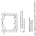
- FIGS. 1A-B depict two views of an exemplary optical ring; one view is a physical view and the other view is a logical view.
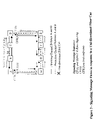
- FIG. 2 depicts an exemplary embodiment of a flow of messages in an optical ring in response to a bi-directional fiber cut according to one aspect of the present invention.
- FIG. 3 depicts an exemplary embodiment of a flow of messages in an optical ring in response to a uni-directional fiber cut according to another aspect of the present invention.
- O-APS Optical Automatic Protection Switching
- FRP Fast Reroute Protocol
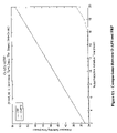
- FIGS. 6A-B depict the sensitivity of protection switching time to nodal processing time of a signaling message, for both O-APS and FRP.
- FIG. 7 depicts the sensitivity of protection switching time to a number of nodes, for both O-APS and FRP.
- FIGS. 8A-B depicts a comparison of protection switching time for O-APS and FRP.
- FIG. 9 depicts a flow chart of an exemplary embodiment of the protection switching for a bi-directional failure according to one aspect of the present invention.
- FIG. 10 depicts a flow chart of an exemplary embodiment of the protection switching for a uni-directional failure according to another aspect of the present invention.
- FIG. 11 depicts an exemplary embodiment for merging channel failure messages according to another aspect of the present invention.
- FIG. 12 depicts an exemplary embodiment for merging channel failure response messages according to another aspect of the present invention.
- any reference herein to “one embodiment” or “an embodiment” means that a particular feature, structure, or characteristic described in connection with the embodiment is included in at least one embodiment of the invention.
- the appearances of the phrase “in one embodiment” in various places in the specification are not necessarily all referring to the same embodiment.
- An exemplary embodiment of the present invention for an Optical Automatic Protection Switching mechanism is designed for protection switching of Optical Channel Shared Protection Rings (OCh/SPRING). More specifically, the embodiment is applicable to optical rings built from flexible Optical Add-Drop Ring Multiplexers (OADMs).
- OADMs Optical Add-Drop Ring Multiplexers
- the exemplary embodiment achieves fast, scalable, end-to-end restoration in OCh/SPRING architectures by employing the following techniques:
- the physical topology includes two counter-rotated fiber rings, in which light travels uni-directionally along each fiber.
- the logical ring topology is constituted by bi-directional links between nodes.
- a bi-directional link is realized by two uni-directional physical fibers.
- FIG. 1 An example is shown in FIG. 1 .
- the example shows an Optical Channel Shared Protection Ring (OCH/Spring) circuit between two endpoints A and D. Its working channel traverses nodes ADCD and its corresponding protection channel travels along nodes DEFGHA. Working and protection channels are carried on different wavelengths.
- OCH/Spring Optical Channel Shared Protection Ring
- the Optical Automatic Protection Switching mechanism Whenever a failure is detected at any endpoints, the Optical Automatic Protection Switching mechanism will be invoked. Both bi-directional and uni-directional failures are taken into account in this mechanism.
- an IP based common control channel exists between any adjacent nodes.
- two end nodes reside within the same protection domain.
- failure detection is end-to-end, and relies on the lower layer failure detection mechanisms that could be vendor specific.
- provisioning for the switching from the working to the protection bi-directionally can be initiated from both end nodes, and does not have to be sequential from the source to destination. This translates to a requirement where the protection wavelength and port information are reserved and fixed and each node can do provisioning or switching from the working to protection independently.
- each node includes all necessary information to perform its protection switching actions, including knowledge of all incoming port mappings, all outgoing port mappings, and all reserved wavelengths. For those applications that operate in the electrical domain, the reserved frequencies must also be known in the node.
- both endpoints A and D detect a failure via a lower layer mechanism that is vendor specific.
- both endpoint nodes (A and D) initiate protection switching by generating channel failure (CF) messages toward each other along the protection path (e.g., the long path).
- CF channel failure
- each node Upon receiving the first channel failure message, regardless of where it is originated, each node initiates protection switching actions for both directions and forwards the channel failure message to the next node uni-directionally.
- the channel failure message can either be forwarded prior to initiating protection switching actions or after do so. But in either case, the channel failure message propagation is not delayed while protection switching actions are occurring in each node. This ensures rapid notification of all nodes in the optical network, hence reducing the delays.
- this embodiment forwards the channel failure message to the next node. This reduces the total protection switching delay time from a sum of the individual delays in each node to the delay of the slowest node, plus the signaling time to reach the slowest node and the processing time at each node.
- each of the nodes Upon receiving the second channel failure message, regardless of where it is originated, each of the nodes forwards the second channel failure message to the next node uni-directionally. Given that the node did not forward the first received channel failure response message until all protection switching actions in the node were complete, this second channel failure response message need not be delayed.
- the corresponding Channel Failure Response (CFR) messages will be initiated at end nodes if and only if the following two conditions are both met. First, protection switching actions for both directions are completed. Second, a channel failure message that was originated from the other end node has arrived.
- CFR Channel Failure Response
- the channel failure response messages will not be forwarded in the intermediate nodes unless protection switching actions for both directions are completed.
- all intermediate nodes will perform following actions. First, upon receiving the first channel failure response message, the intermediate node checks whether associated protection switching actions for both directions are completed. If the answer is yes, then the intermediate node forwards the channel failure response message to the next node in the protection link (unless of course this is the second of the two channel failure response messages to be received by the intermediate node). Otherwise the intermediate node waits until associated protection switching actions for both directions are completed and then forwards the channel failure response message to the next node.
- the intermediate node Upon receiving the second channel failure response message, the intermediate node forward the second channel failure response message to the next node. This can be done without delay, as the intermediate node has by definition completed its protection switching actions due to its response to the first received channel failure response message.
- an end node sends out a channel failure message and the end node claims the completion of protection switching only after it receives a channel failure response message and only then switches the working traffic to the protection channel.
- the far-end node sends the channel failure response message and the intermediate nodes forward the channel failure response message, only after the appropriate protection switching actions are completed in both directions at the respective nodes. So, when the channel failure response message reaches the end node that generated the channel failure message, it is safe to switch working traffic to protection channel at that end node.
- a timer is started when an end node sends out a channel failure message. If the timer expires before that particular end node gets its channel failure response message back, then the end node will know something is wrong and protection switching cannot be completed.
- FIG. 2 demonstrates how messages are being forwarded during the protection switching process for bi-directional failure.
- CF(A) stands for the case where a channel failure message is originated from end node A; and CFR(A) stands for the corresponding channel failure response message.
- FIG. 9 depicts an exemplary embodiment 90 of a method for performing protection switching in flow chart summary form.
- a lower layer mechanism detects failure and informs both endpoint nodes.
- the detection mechanism can vary according to vendor equipment.
- both endpoint nodes generate channel failure messages and transmit them along protection path toward other endpoint node (step 92 ).
- These failure mechanisms may be transmitted at slightly different times, depending upon the mechanism that detects the failure and its relationship to the endpoint nodes, as well as the processing variations in the two endpoint nodes. Nevertheless, these two endpoint nodes will initiate protection switching as quickly as possible from both ends of the protected link.
- Intermediate nodes along the protection path initiate protection switching actions and forward all received channel failure messages to the next node in line along the protection path before completing protection switching actions within the intermediate nodes (step 93 ). This ensures that notification to the intermediate nodes of the failure is not delayed due to protection switching actions within each intermediate node.
- Both endpoint nodes generate channel failure response messages upon receipt of a channel failure message from the other endpoint node and transmit the channel failure response message along protection path back to other endpoint node (step 94 ).
- Intermediate nodes forward channel failure response messages only after completing protection switching actions within the intermediate node (step 95 ). This ensures that when the endpoint node finally receives a channel failure response message, the endpoint node can safely switch working traffic to the protection path.
- the endpoint nodes switch working traffic to the protection path upon receipt of a channel failure response message from the other endpoint node (step 96 ) and the process is complete.
- the end node on the receiving side of the uni-directional failure can detect the failure.
- the end node on the receiving side of the uni-directional failure will initiate the protection switching action by generating a channel failure message towards the source along the protection path (e.g., the longer path) and immediately notify the other end node via working channel, e.g., the short path, by sending, e.g., a SONET K-byte short path signal toward the other end.
- the time to take for the other end node to be notified will be the time of composing the K-byte signaling, plus the propagation delay of speed of light and the processing delay at the receiving end. As soon as the other end node receives the K-byte signal, the other end node sends out the channel failure message along the protection path. It is very unlikely that an end node X receives a channel failure message from the other end node Y on the long path before it receives K-byte short path signal.
- the CFR(X) message will not be sent out in response to CF(X) unless all protection switching actions are completed properly at node Y.
- the protection switching actions for both directions at node Y will occur as soon as node Y receives CF(X) even if node Y has not yet been notified by node X via its K-byte short path signaling.
- FIG. 3 demonstrates how messages are being forwarded during the protection switching process for uni-directional failure.
- CF(A) represents a channel failure (CF) message that is originated from end node A
- CFR(A) represents a channel failure response message (CFR) generated in response to a channel failure message from node A (CF(A)).
- FIG. 10 depicts an exemplary embodiment 100 of a method for performing protection switching for the uni-directional case in flow chart summary form.
- a lower layer mechanism detects a uni-directional failure and informs the destination endpoint node.
- the detection mechanism can vary according to vendor equipment.
- the destination endpoint node generates a channel failure message and transmit it along the protection path toward the source endpoint node (step 102 ).
- the destination endpoint node notifies the source endpoint node via a working channel about the failure (step 103 ).
- the source endpoint node Upon receipt of either the channel failure message from the destination endpoint node via the protection path or the failure notification from the destination endpoint node via the working channel, the source endpoint node generates a channel failure message and transmits it along protection path toward destination endpoint node (step 104 ).
- Intermediate nodes along the protection path initiate protection switching actions and forward all received channel failure messages to the next node in line along the protection path before completing protection switching actions within the intermediate nodes (step 105 ). This ensures that notification to the intermediate nodes of the failure is not delayed due to protection switching actions within each intermediate node.
- Both endpoint nodes generate channel failure response messages upon receipt of a channel failure message from the other endpoint node and transmit the channel failure response message along protection path back to other endpoint node (step 106 ).
- Intermediate nodes forward channel failure response messages only after completing protection switching actions within the intermediate node (step 107 ). This ensures that when the endpoint node finally receives a channel failure response message, the endpoint node can safely switch working traffic to the protection path.
- the endpoint nodes switch working traffic to the protection path upon receipt of a channel failure response message from the other endpoint node (step 108 ) and the process is complete.
- the exemplary embodiments of the present invention for Optical Automatic Protection Switching include multiple aspects.
- One aspect provided includes parallel or simultaneous node configuration and wavelength switching.
- the signaling for protection switching is initiated from both end nodes.
- the embodiment of O-APS allows the initiation of provisioning and configuring protection switching from the working channel or path to the protection channel or path bi-directionally at each node starting from both ends and working towards the middle.
- This “parallel” or “simultaneous” provisioning and switching capability assumes that the switching from the working channel or path to the protection channel or path bi-directionally does not require sequential hardware configuration actions from the source node to the destination node (or vice versa).
- the protection wavelength and port information are reserved and fixed.
- each OADM node has the necessary knowledge to provision the optical switching fabric to do the switching from the working channel to the protection channel without additional input from other nodes or without requiring accessing of information outside the node.
- the above method of “parallel” switching can be further generalized to a mesh network for dedicated protection schemes, in which each OXC can provision the cross connection to switch from the working channel to the protection channel independently because it has already the knowledge about the dedicated resource (e.g., wavelengths) and the incoming and outgoing port mappings.
- each OXC can provision the cross connection to switch from the working channel to the protection channel independently because it has already the knowledge about the dedicated resource (e.g., wavelengths) and the incoming and outgoing port mappings.
- the exemplary embodiment for O-APS uses an optimized nodal behavior in response to the protection switching signaling, which reduces holding times at each node, thereby improving the end-to-end restoration performance.
- the exemplary embodiment for O-APS reduces the dependency of the total protection switching time with respect to the configuration/switching time at each individual node.
- an intermediate node upon receiving the first channel failure message, will initiate the switching action bi-directionally. It does not wait till the completion of the action before it forwards channel failure message uni-directionally to the next node.
- an intermediate node upon receiving the first channel failure response message, will check to make sure that its switching action is complete before it forwards the channel failure response message uni-directionally to the next node in the protection path.
- the embodiment of O-APS makes the total protection switching time less dependent upon the provisioning/configuration/switching time at each individual node.
- this embodiment of the present invention significantly reduces the delays by removing the sequential dependencies and converting them to operations that occur generally in parallel.
- the rate limiting step now becomes the slowest provisioning node (i.e., the node that takes the longest to complete its protection switching) rather than the sum of the times of all nodes in the protection path.
- an embodiment of the O-APS uses a special failure notification mechanism for the destination node to quickly notify the source node of the failure.
- a special failure notification mechanism for the destination node to quickly notify the source node of the failure.
- the source node As only the end node on the receiving side of the uni-directional failure can detect the failure, the source node must be informed. After detecting a failure, the end node on the receiving side of the uni-directional failure (i.e., the destination node) will initiate the protection switching action by generating a channel failure message and sending the channel failure message towards the source node along the protection path (the longer path). At the same time, or shortly thereafter or shortly before, the destination node will immediately notify the other end node (i.e., the source node) via a working channel between the source and destination node, i.e., the short path, by sending, for example, a K-byte SONET short path signal, toward the other end.
- the end node on the receiving side of the uni-directional failure i.e., the destination node
- the destination node will immediately notify the other end node (i.e., the source node) via a working channel between the source and destination node, i.e., the short
- the time needed for the other end node to be notified will be the time of composing the K-byte signal plus the propagation delay of the speed of light through the network and the processing delay at the receiving end.
- the source node receives the K-byte signal, the source node sends out its channel failure message along the protection path to initiate protection switching along the protection path from its end.
- the second arrived CFR could have its corresponding protection switching actions completed before the protection switching actions corresponding to the earlier arrived CFR.
- This aspect of the present invention provides for these eventualities. Assuming both of the received CFR messages are traveling along the same direction, without losing information, these two CFR messages can be merged into one single combination message and sent out. The subsequent nodes along the path then check the contents of this combination message and take appropriate actions, as described above. For example, if the combination CFR message requires completion of protection switching actions in the recipient node for multiple circuits, then the combination CFR message is not forwarded until these actions are completed. If the recipient node is a destination node for one of the CFR messages, then the one CFR message is stripped from the combination message before being forwarded. This occurs in addition to whatever actions by the destination node are required in response to the one CFR message, such as switching of the working traffic to the protection path, which switching may be done before or simultaneous with the stripping or forwarding steps.
- Another scenario will be the case where multiple circuits detect a failure at the same end node simultaneously. Then there will be multiple CF messages being composed. Furthermore, initiating a CF message from an end node normally takes more time than processing a receiving signaling message. Thus, rather than sending each individual CF message one by one, those multiple channel failure messages can be merged or aggregated into one combination CF message and sent out.
- merging signaling messages occurs as follows. Multiple channel failure (CF) messages can be merged into one combination channel failure (CF) message as long as they travel on the same direction. In other words, these messages must be traveling to at least the same next node in the optical network (step 111 - 112 ).
- CF channel failure
- the protection switching actions will be initiated for all embedded circuits (step 113 ). In other words, all actions that would have been taken if the constituent elements of the combination CF message were received separately are taken in response to the combination channel failure message. So, if the combination channel failure message includes three separate channel failure messages for three separate channels or circuits, the protection switching for each of the three separate channels or circuits is initiated in response to this channel failure message. If, however, one of the channel failure messages in the combination channel failure message is redundant to an earlier received channel failure message from a different end point, then the node simply forwards the channel failure message on.
- CF combination channel failure
- the combination channel failure message is then forwarded to the next node before completing the protection switching actions in the intermediate nodes necessitated by the combined channel failure message (step 114 ).
- a combination channel failure message includes a channel failure message from one end node related to an end node that has received the combination channel failure message
- the corresponding channel failure message is removed (step 115 ).
- the corresponding channel information is stripped out of the combination channel failure message whenever it arrives at its end node.
- the combination channel failure message is not discarded until all corresponding end nodes of embedded circuits have been visited by this particular combination channel failure message (step 116 ).
- multiple channel failure response (CFR) messages can be merged into one combination channel failure response message when following conditions are met simultaneously.
- CFR channel failure response
- all of these channel failure response messages to be merged must all be traveling in the same direction (step 121 ). In other words, these multiple channel failure response messages must at least be destined for the same next node in the optical network.
- the channel failure response message sitting at the head of FIFO queue will determine which other channel failure response messages will be part of the combination channel failure response message whenever it is ready to be sent. For example, the channel failure response message at the head of the queue will merge all other channel failure response messages whose corresponding protection switching actions are complete when the protection switching actions for the channel failure response message at the head of the queue are complete (step 122 ).
- the protection switching actions of corresponding circuits of all other embedded channel failure response messages in the combination channel failure response message must be completed before the combination channel failure response message is ready to be sent out.
- the corresponding channel information will be stripped out of the combination CFR message whenever it arrives at its end node (step 124 ).
- the CFR message intended for a particular end node will be removed from the combination CFR message before sending the combination message on to other nodes in the network. This prevents undue message length and processing.
- the combination CFR message is not discarded until all corresponding end nodes of all circuits related to the CFR messages included in the combination CFR message have been visited by this particular combination CFR message (step 125 ). This also ensures that all CFR messages reach their appropriate destinations.
- merging signaling messages reduces signaling volume in an optical network.
- message merging also complicates the message processing process. The performance benefit of message merging becomes more appealing when the number of affected channels increases and the ring size is getting larger.
- FRP Internet Protocol-(IP) based fast restoration protocol
- IETF Internet Engineering Task Force
- the end-to-end channel restoration signaling is accomplished by designating an endpoint as a channel owner. It is composed of two sub-cycles: fault indication and protection switching. If the channel owner can detect faults via a lower layer mechanism, the fault indication cycle can be bypassed. The restoration/protection switching along the protection path can only be activated when the signaling message (End-to-End Switchover Request Message) initiated from the channel owner (upon failure detection or receiving failure notification) is being received at intermediate nodes.
- the signaling message End-to-End Switchover Request Message
- Each node upon receiving the End-to-End Switchover Request, will make appropriate cross connections to setup the protection path. After the action is completed, a node will forward the End-to-End Switchover Request to the next node along the path to the destination node.
- the restoration/protection cycle is completed when the channel owner receives the response message (End-to-End Switchover Response Message) from another endpoint.
- the performance measure we use is the protection switching time that is defined as the time between the time instance that a failure has been detected at any of two end nodes and the time instance that working traffic has been safely moved on to protection path in an error free protection path setup cycle.
- both end nodes of an OCh/SPRING working channel will detect the hi-directional failure (e.g., loss of signal) almost at the same time.
- the protection switching actions on protection path will be initiated at each node whenever that node receives the first CF message no matter where that CF message is originated.
- node i where i ⁇ (N ⁇ M)/2, will most likely receives its first CF message from reference point node Y and node i, where i>(N ⁇ M)/2, will most likely receives its first CF message from the other end node X.
- ⁇ ⁇ ⁇ t i ⁇ Thw - ( N - M ) * ( Tn + Tp ) - Tinit - ⁇ ⁇ ⁇ t i - 1 for ⁇ ⁇ i ⁇ 1 2 ⁇ ( N - M ) ⁇ ⁇ and ( Thw - ( N - M ) * ( Tn + Tp ) - Tinit - ⁇ ⁇ ⁇ t i - 1 ) > 0 Thw - 2 * i * ( Tn + Tp ) - Tinit - ⁇ ⁇ ⁇ t i - 1 for ⁇ ⁇ i > 1 2 ⁇ ( N - M ) ⁇ ⁇ and ( Thw - 2 * i * ( Tn + Tp ) - Tinit - ⁇ ⁇ ⁇ t i - 1 0 0 otherwise
- FIGS. 4-8 demonstrate the non-linearity nature of protection switching time in the proposed O-APS, subject to various parameters as opposed to the linearity in FRP. This non-linearity allows one to have a larger ring for a given protection switching time requirement while keeping other parameters fixed.
- the analytical analysis also reveals that in O-APS the ratio of nodal protection activation time to the one-way delay of a CF message is the most critical factor. If the ratio is less than one, the protection switching activation time has no impacts on the total protection switching time as shown FIGS. 4 and 5 .
- optical mesh networks are not limited to optical ring networks.
- equipment residing in optical ring networks different in nature from those in optical mesh networks, they also tackle the issues on different spaces in terms of customers needs for protection switching.
- OCh/SPRING is a unique service that can only be offered on optical ring networks.
- optical rings are expected to have the same level of performance as conventional SONET APS where K bytes in SONET headers are used to signal the protection switching.
- IP packet processing delay can be introduced while examining the content of the signaling packet and queuing delay in the forwarding process.
- nodal protection activation time is very much technology dependent in particular. One could very well expect a wide range of differences among various vendors depending on whether it is an all-optical transparent box or an O-E-O type of box.
- the embodiments of the present invention for O-APS break the linear growth of protection switching time subject to nodal protection activation time.
- both endpoints are allowed to initiate protection switching signaling process.
- the integrity of the O-APS algorithm is guaranteed by its well-defined associated nodal behavior along the protection path. As a result, the degree of protection switching time's dependency on nodal protection activation time is greatly reduced.
Landscapes
- Engineering & Computer Science (AREA)
- Computer Networks & Wireless Communication (AREA)
- Signal Processing (AREA)
- Optical Communication System (AREA)
- Data Exchanges In Wide-Area Networks (AREA)
Abstract
Description
-
- Tn: nodal processing time of signaling message.
- Tp: propagation time between two adjacent nodes.
- Tinit: time to initiate a signaling message (CF or End-to-End Switchover Request).
- Tbs: time to switch working traffic from failed working channel to protection channel after receiving a CFR message or End-to-End Switchover Response message.
- Thw: time for activating protection also called nodal protection activation time that is the time to take for a node on protection path to be ready to forward working traffic switched from failed working channel.
- N: total number of nodes on the ring that equals to the total spans/hops on the ring.
- M: total number of hops on a working channel.
- T: protection switching time.
- i: the index for nodes. Assume two end nodes X and Y, i indicates the distance of a node in terms of hops from the end node Y that generated a CFR(X) for a given channel. To facilitate the discussion we name Y as the reference point.
- Δti: time that a CFR message has to wait for protection actions being completed at node i.
T=2*(N−M)*(Tn+Tp)+Tbs+Tinit+Thw−(Tn+Tp)=(2*(N−M)−1)*(Tn+Tp)+Tbs+Tinit+Thw
Claims (8)
Priority Applications (2)
| Application Number | Priority Date | Filing Date | Title |
|---|---|---|---|
| US10/200,066 US7277631B1 (en) | 2001-07-20 | 2002-07-19 | Method and apparatus for processing protection switching mechanism in optical channel shared protection rings |
| US11/866,363 US7596313B1 (en) | 2001-07-20 | 2007-10-02 | Method and apparatus for processing protection switching mechanism in optical channel shared protection rings |
Applications Claiming Priority (2)
| Application Number | Priority Date | Filing Date | Title |
|---|---|---|---|
| US30671001P | 2001-07-20 | 2001-07-20 | |
| US10/200,066 US7277631B1 (en) | 2001-07-20 | 2002-07-19 | Method and apparatus for processing protection switching mechanism in optical channel shared protection rings |
Related Child Applications (1)
| Application Number | Title | Priority Date | Filing Date |
|---|---|---|---|
| US11/866,363 Continuation US7596313B1 (en) | 2001-07-20 | 2007-10-02 | Method and apparatus for processing protection switching mechanism in optical channel shared protection rings |
Publications (1)
| Publication Number | Publication Date |
|---|---|
| US7277631B1 true US7277631B1 (en) | 2007-10-02 |
Family
ID=38535864
Family Applications (2)
| Application Number | Title | Priority Date | Filing Date |
|---|---|---|---|
| US10/200,066 Expired - Fee Related US7277631B1 (en) | 2001-07-20 | 2002-07-19 | Method and apparatus for processing protection switching mechanism in optical channel shared protection rings |
| US11/866,363 Expired - Fee Related US7596313B1 (en) | 2001-07-20 | 2007-10-02 | Method and apparatus for processing protection switching mechanism in optical channel shared protection rings |
Family Applications After (1)
| Application Number | Title | Priority Date | Filing Date |
|---|---|---|---|
| US11/866,363 Expired - Fee Related US7596313B1 (en) | 2001-07-20 | 2007-10-02 | Method and apparatus for processing protection switching mechanism in optical channel shared protection rings |
Country Status (1)
| Country | Link |
|---|---|
| US (2) | US7277631B1 (en) |
Cited By (10)
| Publication number | Priority date | Publication date | Assignee | Title |
|---|---|---|---|---|
| US20030223745A1 (en) * | 2002-05-30 | 2003-12-04 | Fujitsu Limited | Optical communication node and optical network system |
| US20040111606A1 (en) * | 2002-12-10 | 2004-06-10 | Wong Allen Tsz-Chiu | Fault-tolerant multicasting network |
| US20060221811A1 (en) * | 2003-08-05 | 2006-10-05 | Andrea Allasia | Method for providing extra-traffic paths with connection protection in a communication network, related network and computer program product therefor |
| US20090125639A1 (en) * | 2007-11-11 | 2009-05-14 | Weed Instrument Company, Inc. | Method, apparatus and computer program product for ring network communication |
| US7715713B1 (en) | 2002-09-30 | 2010-05-11 | Meriton Networks Us Inc. | Method and apparatus for providing multiple optical channel protection switching mechanisms in optical rings |
| CN101162946B (en) * | 2007-11-21 | 2011-08-24 | 北京邮电大学 | Fault notification device and method based on serial homologous mechanism |
| US20120163803A1 (en) * | 2009-09-04 | 2012-06-28 | Xiaobing Zi | Information processing method in optical network, optical communication apparatus and system |
| EP2312792A4 (en) * | 2008-07-22 | 2014-08-06 | Zte Corp | PROTECTIVE PROTOCOL DEVICE FOR NETWORK NOD AND METHOD FOR PROCESSING DEVICE PROTECTION SWITCHING |
| CN112839350A (en) * | 2020-12-30 | 2021-05-25 | 杭州萤石软件有限公司 | A method, device, and system for fault detection in a multi-frequency wireless mesh network |
| JP2022528044A (en) * | 2019-03-25 | 2022-06-08 | エルエス、エレクトリック、カンパニー、リミテッド | How to recover the network when a communication failure occurs in the RAPIEnet system |
Families Citing this family (5)
| Publication number | Priority date | Publication date | Assignee | Title |
|---|---|---|---|---|
| US7675899B2 (en) * | 2005-11-30 | 2010-03-09 | Alcatel-Lucent Usa Inc. | Packet-aware transport architecture for enhanced data volume |
| CN100563354C (en) * | 2006-07-03 | 2009-11-25 | 华为技术有限公司 | A Method for Realizing Service Protection in Automatic Switching Optical Network |
| US8203938B2 (en) * | 2008-05-22 | 2012-06-19 | Level 3 Communications, Llc | Multi-router IGP fate sharing |
| WO2011027361A2 (en) * | 2009-09-07 | 2011-03-10 | Tejas Networks Limited | A method and system for ring protection switching |
| CN102857316B (en) * | 2011-06-29 | 2016-12-07 | 中兴通讯股份有限公司 | A kind of method and system realizing source looped network protection |
Citations (9)
| Publication number | Priority date | Publication date | Assignee | Title |
|---|---|---|---|---|
| US5412651A (en) * | 1993-02-11 | 1995-05-02 | Nec America, Inc. | Structure and method for combining PCM and common control data on a backplane bus |
| US6272107B1 (en) * | 1998-05-12 | 2001-08-07 | 3Com Corporation | Method of path restoration in an ATM network utilizing point to point switched virtual circuits |
| US20020138614A1 (en) | 2001-03-20 | 2002-09-26 | Hall Dennis W. | Method and apparatus to manage network addresses |
| US6721502B1 (en) | 2000-09-30 | 2004-04-13 | Lucent Technologies Inc. | Shared optical protection ring architecture |
| US6724781B1 (en) * | 1999-08-23 | 2004-04-20 | Marconi Communications, Inc. | System and method for packet transport in a ring network |
| US6763190B2 (en) | 2000-03-03 | 2004-07-13 | Lucent Technologies Inc. | Network auto-provisioning and distributed restoration |
| US6795394B1 (en) * | 2000-04-26 | 2004-09-21 | Nortel Networks Limited | Data network having enhanced availability of extra traffic |
| US6970417B1 (en) | 1999-12-28 | 2005-11-29 | At&T Corp. | Methods and systems for fast restoration in a mesh network of optical cross connects |
| US7031299B2 (en) | 2000-01-28 | 2006-04-18 | At&T Corp. | Control of optical connections in an optical network |
Family Cites Families (2)
| Publication number | Priority date | Publication date | Assignee | Title |
|---|---|---|---|---|
| CA2162200A1 (en) * | 1994-11-23 | 1996-05-24 | Gagan Lal Choudhury | Efficiently providing multiple grades of service with protection against overloads in shared resources |
| US6738748B2 (en) * | 2001-04-03 | 2004-05-18 | Accenture Llp | Performing predictive maintenance on equipment |
-
2002
- 2002-07-19 US US10/200,066 patent/US7277631B1/en not_active Expired - Fee Related
-
2007
- 2007-10-02 US US11/866,363 patent/US7596313B1/en not_active Expired - Fee Related
Patent Citations (9)
| Publication number | Priority date | Publication date | Assignee | Title |
|---|---|---|---|---|
| US5412651A (en) * | 1993-02-11 | 1995-05-02 | Nec America, Inc. | Structure and method for combining PCM and common control data on a backplane bus |
| US6272107B1 (en) * | 1998-05-12 | 2001-08-07 | 3Com Corporation | Method of path restoration in an ATM network utilizing point to point switched virtual circuits |
| US6724781B1 (en) * | 1999-08-23 | 2004-04-20 | Marconi Communications, Inc. | System and method for packet transport in a ring network |
| US6970417B1 (en) | 1999-12-28 | 2005-11-29 | At&T Corp. | Methods and systems for fast restoration in a mesh network of optical cross connects |
| US7031299B2 (en) | 2000-01-28 | 2006-04-18 | At&T Corp. | Control of optical connections in an optical network |
| US6763190B2 (en) | 2000-03-03 | 2004-07-13 | Lucent Technologies Inc. | Network auto-provisioning and distributed restoration |
| US6795394B1 (en) * | 2000-04-26 | 2004-09-21 | Nortel Networks Limited | Data network having enhanced availability of extra traffic |
| US6721502B1 (en) | 2000-09-30 | 2004-04-13 | Lucent Technologies Inc. | Shared optical protection ring architecture |
| US20020138614A1 (en) | 2001-03-20 | 2002-09-26 | Hall Dennis W. | Method and apparatus to manage network addresses |
Non-Patent Citations (4)
| Title |
|---|
| "Computer Networks" by A. Tanenbaum, Prentice-Hall, 1981, p. 141. * |
| GR-1230-Core, "Sonet BLSR Equipment Generic Criteria", Issue 4, Dec. 1998, Section 6. |
| S. Ramamurthy et al., "Survivable WDM Mesh Networks, Part II - Restoration", IEEE, 1999. |
| Y. Park, "Architecture of a Bidirectional Wavelength Path Switched Ring and Its Implementation Schemes", IEEE Photonics Technology Letters, vol. 12, No. 9, Sep. 2000. * |
Cited By (17)
| Publication number | Priority date | Publication date | Assignee | Title |
|---|---|---|---|---|
| US20030223745A1 (en) * | 2002-05-30 | 2003-12-04 | Fujitsu Limited | Optical communication node and optical network system |
| US7756416B2 (en) * | 2002-05-30 | 2010-07-13 | Fujitsu Limited | Optical communication node and optical network system |
| US7715713B1 (en) | 2002-09-30 | 2010-05-11 | Meriton Networks Us Inc. | Method and apparatus for providing multiple optical channel protection switching mechanisms in optical rings |
| US20040111606A1 (en) * | 2002-12-10 | 2004-06-10 | Wong Allen Tsz-Chiu | Fault-tolerant multicasting network |
| US7486612B2 (en) * | 2002-12-10 | 2009-02-03 | Tellabs Petaluma, Inc. | Fault-tolerant multicasting network |
| US7746767B2 (en) * | 2003-08-05 | 2010-06-29 | Telecom Italia S.P.A. | Method for providing extra-traffic paths with connection protection in a communication network, related network and computer program product therefor |
| US20060221811A1 (en) * | 2003-08-05 | 2006-10-05 | Andrea Allasia | Method for providing extra-traffic paths with connection protection in a communication network, related network and computer program product therefor |
| US20090125639A1 (en) * | 2007-11-11 | 2009-05-14 | Weed Instrument Company, Inc. | Method, apparatus and computer program product for ring network communication |
| US20090122695A1 (en) * | 2007-11-11 | 2009-05-14 | Weed Instrument Company, Inc. | Method, apparatus and computer program product for redundant ring communication |
| US7990851B2 (en) | 2007-11-11 | 2011-08-02 | Weed Instrument, Inc. | Method, apparatus and computer program product for redundant ring communication |
| US8200850B2 (en) | 2007-11-11 | 2012-06-12 | Weed Instrument, Inc. | Method, apparatus and computer program product for ring network communication |
| CN101162946B (en) * | 2007-11-21 | 2011-08-24 | 北京邮电大学 | Fault notification device and method based on serial homologous mechanism |
| EP2312792A4 (en) * | 2008-07-22 | 2014-08-06 | Zte Corp | PROTECTIVE PROTOCOL DEVICE FOR NETWORK NOD AND METHOD FOR PROCESSING DEVICE PROTECTION SWITCHING |
| US20120163803A1 (en) * | 2009-09-04 | 2012-06-28 | Xiaobing Zi | Information processing method in optical network, optical communication apparatus and system |
| US8787750B2 (en) * | 2009-09-04 | 2014-07-22 | Huawei Technologies Co., Ltd. | Information processing method in optical network, optical communication apparatus and system |
| JP2022528044A (en) * | 2019-03-25 | 2022-06-08 | エルエス、エレクトリック、カンパニー、リミテッド | How to recover the network when a communication failure occurs in the RAPIEnet system |
| CN112839350A (en) * | 2020-12-30 | 2021-05-25 | 杭州萤石软件有限公司 | A method, device, and system for fault detection in a multi-frequency wireless mesh network |
Also Published As
| Publication number | Publication date |
|---|---|
| US7596313B1 (en) | 2009-09-29 |
Similar Documents
| Publication | Publication Date | Title |
|---|---|---|
| US7596313B1 (en) | Method and apparatus for processing protection switching mechanism in optical channel shared protection rings | |
| Qiao et al. | Optical burst switching (OBS)–a new paradigm for an optical Internet | |
| EP1087573B1 (en) | dual counter rotating ring network control system | |
| US7274869B1 (en) | System and method for providing destination-to-source protection switch setup in optical network topologies | |
| US8089864B2 (en) | Network restoration | |
| US7046619B2 (en) | Method and system for bi-directional path switched network | |
| EP1639856B1 (en) | Adaptive framework for closed-loop protocols over photonic burst switched networks | |
| EP1391068B1 (en) | Restoration protection in communication networks | |
| US20050063701A1 (en) | Method and system to recover resources in the event of data burst loss within WDM-based optical-switched networks | |
| EP1735950B1 (en) | Line-level path protection in the optical layer | |
| Chlamtac et al. | Light-trails: A solution to IP centric communication in the optical domain | |
| US7269346B1 (en) | Optical automatic protection switching mechanism for optical channel shared protection rings | |
| Veitch et al. | ATM network resilience | |
| EP1282331B1 (en) | Connection setup strategies in optical transport networks | |
| EP1489784A1 (en) | Restoration in an automatically switched optical transport network | |
| US20030043427A1 (en) | Method of fast circuit recovery using local restoration | |
| Zhu et al. | Dynamic traffic grooming in optical WDM mesh networks with distributed control | |
| Imajuku et al. | GMPLS based survivable photonic network architecture | |
| Xing et al. | BLE protection scheme for light-trail WDM mesh networks | |
| Herzog et al. | Proxy stripping: a performance-enhancing technique for optical metropolitan area ring networks | |
| Seno et al. | Optical path protection with fast extra path preemption | |
| Velasco et al. | ROADM design for OMS-DPRing protection in GMPLS-based optical networks | |
| Correia et al. | Recovery time analysis of WDM protection schemes | |
| Alicherry et al. | FASTeR: sub-50-ms shared restoration in mesh networks | |
| Kurki et al. | Wavelength Router as a Transport Platform for IP |
Legal Events
| Date | Code | Title | Description |
|---|---|---|---|
| AS | Assignment |
Owner name: PHOTURIS, INC., NEW JERSEY Free format text: ASSIGNMENT OF ASSIGNORS INTEREST;ASSIGNORS:IYER, RAVICHANDRAN;SAMPANGI, MANJUNATH;RODRIQUEZ-MORAL, ANTONIO;AND OTHERS;REEL/FRAME:013509/0500;SIGNING DATES FROM 20020926 TO 20021014 |
|
| AS | Assignment |
Owner name: JURISTA, MR. STEVEN Z., NEW JERSEY Free format text: ASSIGNMENT OF ASSIGNORS INTEREST;ASSIGNOR:PHOTURIS, INC.;REEL/FRAME:014999/0199 Effective date: 20040408 |
|
| AS | Assignment |
Owner name: MAHI NETWORKS, INC., CALIFORNIA Free format text: ASSIGNMENT OF ASSIGNORS INTEREST;ASSIGNOR:JURISTA, MR. STEVEN Z.;REEL/FRAME:015154/0163 Effective date: 20040608 |
|
| AS | Assignment |
Owner name: MAHI NETWORKS, INC., CALIFORNIA Free format text: SALE DUE TO BANKRUPTCY;ASSIGNOR:PHOTURIS, INC.;REEL/FRAME:016996/0483 Effective date: 20040506 Owner name: MAHI NETWORKS, INC.,CALIFORNIA Free format text: SALE DUE TO BANKRUPTCY;ASSIGNOR:PHOTURIS, INC.;REEL/FRAME:016996/0483 Effective date: 20040506 |
|
| AS | Assignment |
Owner name: MERITON NETWORKS US INC., DELAWARE Free format text: MERGER;ASSIGNOR:MAHI NETWORKS, INC.;REEL/FRAME:016996/0958 Effective date: 20051110 Owner name: MERITON NETWORKS US INC.,DELAWARE Free format text: MERGER;ASSIGNOR:MAHI NETWORKS, INC.;REEL/FRAME:016996/0958 Effective date: 20051110 |
|
| CC | Certificate of correction | ||
| REMI | Maintenance fee reminder mailed | ||
| LAPS | Lapse for failure to pay maintenance fees | ||
| STCH | Information on status: patent discontinuation |
Free format text: PATENT EXPIRED DUE TO NONPAYMENT OF MAINTENANCE FEES UNDER 37 CFR 1.362 |
|
| FP | Lapsed due to failure to pay maintenance fee |
Effective date: 20111002 |
|
| AS | Assignment |
Owner name: MERITON NETWORKS, INC., TEXAS Free format text: ASSIGNMENT OF ASSIGNORS INTEREST;ASSIGNOR:MERITON NETWORKS US, INC.;REEL/FRAME:028388/0810 Effective date: 20061201 |
|
| AS | Assignment |
Owner name: XTERA COMMUNICATIONS, INC., TEXAS Free format text: ASSIGNMENT OF ASSIGNORS INTEREST;ASSIGNOR:MERITON NETWORKS, INC.;REEL/FRAME:028541/0891 Effective date: 20120501 |