US7275855B2 - Vehicle Lamp - Google Patents
Vehicle Lamp Download PDFInfo
- Publication number
- US7275855B2 US7275855B2 US11/132,381 US13238105A US7275855B2 US 7275855 B2 US7275855 B2 US 7275855B2 US 13238105 A US13238105 A US 13238105A US 7275855 B2 US7275855 B2 US 7275855B2
- Authority
- US
- United States
- Prior art keywords
- vehicle lamp
- lamp
- stud
- metal sheet
- base
- Prior art date
- Legal status (The legal status is an assumption and is not a legal conclusion. Google has not performed a legal analysis and makes no representation as to the accuracy of the status listed.)
- Expired - Fee Related, expires
Links
- 239000004033 plastic Substances 0.000 claims abstract description 25
- 229920003023 plastic Polymers 0.000 claims abstract description 25
- 230000003014 reinforcing effect Effects 0.000 claims abstract description 10
- 239000002184 metal Substances 0.000 claims description 34
- 239000000463 material Substances 0.000 claims description 14
- 230000001681 protective effect Effects 0.000 description 7
- 229920000106 Liquid crystal polymer Polymers 0.000 description 5
- 239000004977 Liquid-crystal polymers (LCPs) Substances 0.000 description 5
- 239000004697 Polyetherimide Substances 0.000 description 3
- 238000001746 injection moulding Methods 0.000 description 3
- 229920001601 polyetherimide Polymers 0.000 description 3
- 229910001220 stainless steel Inorganic materials 0.000 description 3
- 239000010935 stainless steel Substances 0.000 description 3
- 239000004734 Polyphenylene sulfide Substances 0.000 description 2
- 229910000639 Spring steel Inorganic materials 0.000 description 2
- 238000005266 casting Methods 0.000 description 2
- 239000003365 glass fiber Substances 0.000 description 2
- 229920000069 polyphenylene sulfide Polymers 0.000 description 2
- 229920004738 ULTEM® Polymers 0.000 description 1
- 229920013651 Zenite Polymers 0.000 description 1
- 239000013078 crystal Substances 0.000 description 1
- 239000002178 crystalline material Substances 0.000 description 1
- 230000001419 dependent effect Effects 0.000 description 1
- 239000012799 electrically-conductive coating Substances 0.000 description 1
- 229910052736 halogen Inorganic materials 0.000 description 1
- 150000002367 halogens Chemical class 0.000 description 1
- 239000007791 liquid phase Substances 0.000 description 1
- 238000004519 manufacturing process Methods 0.000 description 1
- 229910001507 metal halide Inorganic materials 0.000 description 1
- 150000005309 metal halides Chemical class 0.000 description 1
- 230000003763 resistance to breakage Effects 0.000 description 1
- 229920001169 thermoplastic Polymers 0.000 description 1
- 239000004416 thermosoftening plastic Substances 0.000 description 1
- 238000003466 welding Methods 0.000 description 1
- 229910052724 xenon Inorganic materials 0.000 description 1
- FHNFHKCVQCLJFQ-UHFFFAOYSA-N xenon atom Chemical compound [Xe] FHNFHKCVQCLJFQ-UHFFFAOYSA-N 0.000 description 1
- PGNWIWKMXVDXHP-UHFFFAOYSA-L zinc;1,3-benzothiazole-2-thiolate Chemical compound [Zn+2].C1=CC=C2SC([S-])=NC2=C1.C1=CC=C2SC([S-])=NC2=C1 PGNWIWKMXVDXHP-UHFFFAOYSA-L 0.000 description 1
Images


Classifications
-
- H—ELECTRICITY
- H01—ELECTRIC ELEMENTS
- H01J—ELECTRIC DISCHARGE TUBES OR DISCHARGE LAMPS
- H01J5/00—Details relating to vessels or to leading-in conductors common to two or more basic types of discharge tubes or lamps
- H01J5/50—Means forming part of the tube or lamps for the purpose of providing electrical connection to it
- H01J5/54—Means forming part of the tube or lamps for the purpose of providing electrical connection to it supported by a separate part, e.g. base
-
- F—MECHANICAL ENGINEERING; LIGHTING; HEATING; WEAPONS; BLASTING
- F21—LIGHTING
- F21S—NON-PORTABLE LIGHTING DEVICES; SYSTEMS THEREOF; VEHICLE LIGHTING DEVICES SPECIALLY ADAPTED FOR VEHICLE EXTERIORS
- F21S41/00—Illuminating devices specially adapted for vehicle exteriors, e.g. headlamps
- F21S41/10—Illuminating devices specially adapted for vehicle exteriors, e.g. headlamps characterised by the light source
- F21S41/19—Attachment of light sources or lamp holders
- F21S41/192—Details of lamp holders, terminals or connectors
-
- H—ELECTRICITY
- H01—ELECTRIC ELEMENTS
- H01J—ELECTRIC DISCHARGE TUBES OR DISCHARGE LAMPS
- H01J5/00—Details relating to vessels or to leading-in conductors common to two or more basic types of discharge tubes or lamps
- H01J5/48—Means forming part of the tube or lamp for the purpose of supporting it
Definitions
- the invention relates to a vehicle lamp having a lamp base, which is equipped with the electrical connections of the vehicle lamp, the lamp base having a plastic base part which has at least one integrally formed stud, which serves the purpose of mounting the vehicle lamp in the vehicle headlight.
- Such a vehicle lamp is disclosed, for example, in the European laid-open specification EP 0 786 791 A1.
- This vehicle lamp has a lamp base having a cylindrical base sleeve made of plastic, which is provided with two diametrically arranged studs made of plastic which point radially outwards and which serve the purpose of mounting the lamp in a vehicle headlight.
- a vehicle lamp having a lamp base, which is equipped with the electrical connections of the vehicle lamp, the lamp base having a plastic base part which has at least one integrally formed stud, which serves the purpose of mounting the vehicle lamp in the vehicle headlight, wherein said at least one stud is provided with reinforcing means.
- the vehicle lamp according to the invention has a lamp base, which is provided with the electrical connections of the vehicle lamp and is provided with a plastic base part which has at least one integrally formed stud, which serves the purpose of mounting the vehicle lamp in the vehicle headlight and is equipped with reinforcing means.
- the reinforcing means increase the mechanical robustness, in particular the resistance to breakage, of the at least one stud, with the result that it can be formed as part of a latching mechanism for the purpose of fixing the vehicle lamp in the lampholder of the vehicle headlight.
- the reinforcing means is a metal sheet which is at least partially embedded in the plastic material of the plastic base part.
- the metal sheet increases the mechanical robustness of the at least one stud such that the at least one stud can be formed as part of a latching apparatus, preferably a bayonet fitting.
- a suitable material for the metal sheet is, for example, stainless steel or spring steel.
- the metal sheet is advantageously either embedded in the plastic material of the at least one stud or formed such that it covers at least part of the outer surface of the at least one stud.
- the abovementioned metal sheet is in the form of a lug which is integrally formed on a metal ring.
- the at least one lug can be positioned exactly in the casting mold for the plastic base part provided with the stud, in order for it then to be embedded in the material of the corresponding stud by means of a plastic injection-molding process.
- the abovementioned metal ring also has the advantage that it can additionally be used as an electrical connection for the vehicle lamp.
- FIG. 1 shows a partially sectioned, schematic illustration of a side view of a vehicle lamp in accordance with a preferred exemplary embodiment of the invention
- FIG. 2 shows an enlarged illustration of the section of the lamp base, which is depicted in cross section in FIG. 1 , in accordance with the first exemplary embodiment of the invention
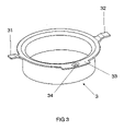
- FIG. 3 shows a schematic illustration of the annular, electrical connection of the vehicle lamp depicted in FIG. 1 ,
- FIG. 4 shows an enlarged illustration of the section of the lamp base, which is depicted in cross section in FIG. 1 , in accordance with the second exemplary embodiment of the invention
- FIG. 5 shows an enlarged illustration of the section of the lamp base, which is depicted in cross section in FIG. 1 , in accordance with the third exemplary embodiment of the invention.
- FIG. 6 shows a partially sectioned, schematic illustration of a side view of a vehicle lamp in accordance with a fourth exemplary embodiment of the invention with an auxiliary starting electrode on the protective bulb.
- the preferred exemplary embodiment of the invention depicted in FIG. 1 is a high-pressure discharge lamp, in particular a halogen metal-vapor high-pressure discharge lamp having an electrical power consumption of approximately 35 watts, which is envisaged for use in a motor vehicle headlight.
- This high-pressure discharge lamp has a discharge vessel, in the interior of which are arranged gas discharge electrodes and an ionizable filling comprising xenon and metal halides for the purpose of producing a gas discharge, and which is surrounded by a transparent, cylindrical protective bulb 1 .
- the protective bulb 1 is fixed directly to the discharge vessel.
- a tubular protrusion l a of the protective bulb 1 is fixed in the plastic lamp base 2 of the high-pressure discharge lamp. Details on the discharge vessel, the protective bulb 1 and the manner in which it is fixed in the lamp base 2 are described, for example, in laid-open specification EP 0 786 791 A1.
- the lamp base 2 has a cylindrical base sleeve 20 , which is made from an electrically insulating thermoplastic withstanding high temperatures and which has two integrally formed, diametrically arranged studs 21 , 22 .
- the two studs 21 , 22 extend along a diameter of the base sleeve 20 and are integrally formed on the outside of the base sleeve 20 .
- the thickness of the studs 21 , 22 i.e. their extent in the longitudinal direction of the lamp, is 3 mm.
- the end 23 of the lamp base 2 which is remote from the protective bulb 1 is in the form of a plug and is equipped with the electrical connections of the lamp.
- One electrical connection of the vehicle lamp is in the form of an annular metal contact 3 which forms part of the outside of the end 23 in the form of a plug.
- the second electrical connection is an axially arranged contact pin, which cannot be seen in the side view in FIG. 1 . Details of this contact pin are described, for example, in the above-cited laid-open specification.
- the annular metal contact 3 is depicted in FIG. 3 . It is made of stainless steel.
- the annular metal contact 3 has two integrally formed, diametrically arranged lugs 31 , 32 which extend radially outwards. These lugs 31 , 32 are each embedded in the plastic material of a stud 21 and 22 , respectively. The lugs 31 , 32 are embedded in this manner in the plastic material of the studs 21 , 22 during the manufacturing process of the base sleeve 20 by means of a plastic injection-molding process.
- the annular metal contact 3 has an integrally formed welding tab 33 , which is bent back in the radial direction, is provided with an aperture 34 and serves the purpose of making electrical contact with the power supply wire of the power return line 4 .
- the lugs 31 , 32 have a thickness or a metal sheet thickness of 0.4 mm. The free ends of the lugs 31 , 32 are embedded centrally in the plastic material of the respective stud 21 and 22 , as illustrated schematically in FIG. 2 .
- FIGS. 4 and 5 show two further exemplary embodiments for reinforcing the studs 21 , 22 of the high-pressure discharge lamp described in more detail above. These exemplary embodiments differ only in terms of the metal sheets which are embedded in the studs 21 , 22 or which surround the studs 21 , 22 . In all of the figures, the same reference numerals have also been used for identical lamp parts.
- a bent-back metal sheet 41 is embedded in each stud 21 , 22 of the base 20 of the high-pressure discharge lamp.
- a first limb 411 of the metal sheet 41 extends into the studs 21 or 22 and is completely surrounded by the plastic material of the stud.
- the second limb 412 of the metal sheet 41 is bent back at right angles from the first limb 411 and is embedded in the plastic material of the cylindrical base part 20 .
- the metal sheet 41 is not connected to the annular contact 3 .
- the upper side and the underside as well as that end face of the stud 21 or 22 which is oriented perpendicular to the radius of the lamp base 20 are surrounded by a metal sheet 51 which is essentially in the form of a U.
- the majority of the surface of the stud 21 or 22 is therefore formed by the metal sheet 51 .
- the U limb 511 of the metal sheet 51 which covers the upper side of the stud 21 or 22 , is provided with a lug 5110 , which is bent back at right angles from the U limb 511 and is embedded in the plastic material of the base 20 .
- the second U limb 512 covers the underside of the stud 21 or 22 , whereas the connecting section 513 of the U limbs 511 , 512 covers the abovementioned end face of the stud 21 and 22 , respectively.
- the metal sheet 51 is not connected to the annular contact 3 .
- the second limb 412 of the metal sheet 41 in accordance with the second exemplary embodiment of the invention or the lug 5110 of the metal sheet 51 in accordance with the third exemplary embodiment of the invention can be electrically conductively connected within the base 20 to an auxiliary electrode of the high-pressure discharge lamp, for example to an auxiliary starting electrode 6 of the high-pressure discharge lamp, the auxiliary starting electrode 6 being applied, for example, as an electrically conductive coating to the protective bulb 1 of the high-pressure discharge lamp, as is illustrated in FIG. 6 in accordance with the fourth exemplary embodiment.
- the electrical contact to the voltage source can be produced, for example, by means of the first limb 411 of the metal sheet 41 which is embedded in the stud 21 and which can protrude from the stud 21 for this purpose, or realized by means of the U limbs 511 , 512 of the metal sheet 51 which partially cover the surface of the stud 21 .
- the auxiliary starting electrode 6 may also be electrically conductively connected to the power return line 4 or be designed to be DC-isolated from the electrodes and power supply lines of the high-pressure discharge lamp.
- the fourth exemplary embodiment corresponds to the exemplary embodiment depicted in FIG. 1 in all details except for the auxiliary starting electrode 6 and the way in which contact is made with said auxiliary starting electrode 6 .
- the metal sheets are made of stainless steel or spring steel.
- the plastic base 20 and the studs 21 integrally formed therewith are made of a plastic which can be subjected to high thermal loads, from the group consisting of polyetherimide (PEI), polyphenylenesulfide (PPS) and liquid crystal polymer (LCP).
- PEI polyetherimide
- PPS polyphenylenesulfide
- LCP liquid crystal polymer
- Polyetherimide which is also known under the trade name ULTEM®, has a glass fiber content of 30 percent, and the studs 21 show a strength of more than 500 newtons, even without the metallic reinforcing means. The elongation at break of this material is 2 percent.
- LCP liquid crystal polymer
- Vectra® or Zenite® the content of glass fibers in the material is between 30 percent and 50 percent.
- the stud strength is approximately 150 newtons to 200 newtons, without metallic reinforcing means.
- the elongation at break has a value of 1.5 percent.
- LCP is a severely anisotropic, highly crystalline material, which forms crystalline regions even in the liquid phase, such that, the stud strength can be optimized by suitably aligning the crystals during casting and injection-molding of the base 20 .
Landscapes
- Engineering & Computer Science (AREA)
- General Engineering & Computer Science (AREA)
- Non-Portable Lighting Devices Or Systems Thereof (AREA)
- Snaps, Bayonet Connections, Set Pins, And Snap Rings (AREA)
- Fastening Of Light Sources Or Lamp Holders (AREA)
- Common Detailed Techniques For Electron Tubes Or Discharge Tubes (AREA)
- Connecting Device With Holders (AREA)
- Lighting Device Outwards From Vehicle And Optical Signal (AREA)
Abstract
Description
Claims (6)
Applications Claiming Priority (2)
| Application Number | Priority Date | Filing Date | Title |
|---|---|---|---|
| DE102004025268.8 | 2004-05-19 | ||
| DE102004025268A DE102004025268A1 (en) | 2004-05-19 | 2004-05-19 | vehicle lamp |
Publications (2)
| Publication Number | Publication Date |
|---|---|
| US20050259432A1 US20050259432A1 (en) | 2005-11-24 |
| US7275855B2 true US7275855B2 (en) | 2007-10-02 |
Family
ID=35079267
Family Applications (1)
| Application Number | Title | Priority Date | Filing Date |
|---|---|---|---|
| US11/132,381 Expired - Fee Related US7275855B2 (en) | 2004-05-19 | 2005-05-19 | Vehicle Lamp |
Country Status (7)
| Country | Link |
|---|---|
| US (1) | US7275855B2 (en) |
| EP (1) | EP1605490B1 (en) |
| JP (1) | JP4838535B2 (en) |
| CN (1) | CN1702804B (en) |
| AT (1) | ATE467226T1 (en) |
| CA (1) | CA2507906A1 (en) |
| DE (2) | DE102004025268A1 (en) |
Cited By (4)
| Publication number | Priority date | Publication date | Assignee | Title |
|---|---|---|---|---|
| US20080088806A1 (en) * | 2006-10-16 | 2008-04-17 | Sanyo Electric Co., Ltd. | Projection display |
| US20090027906A1 (en) * | 2004-08-05 | 2009-01-29 | Koninklijke Philips Electronics, N.V. | Lamp having improved vibration damping |
| US20100176709A1 (en) * | 2006-09-08 | 2010-07-15 | Karin Dressel | Lamp base |
| US20120176798A1 (en) * | 2009-09-08 | 2012-07-12 | Osram Ag | Lamp unit |
Families Citing this family (3)
| Publication number | Priority date | Publication date | Assignee | Title |
|---|---|---|---|---|
| KR20090068329A (en) * | 2006-09-14 | 2009-06-26 | 코닌클리즈케 필립스 일렉트로닉스 엔.브이. | Single-filament halogen incandescent lamps intended for automotive headlamps and methods for manufacturing the same |
| DE102007007523A1 (en) * | 2007-02-15 | 2008-08-21 | Zeibina Kunststoff-Technik Gmbh | Contacting and holding device for incandescent lamps |
| EP4176200A4 (en) * | 2020-07-06 | 2024-07-31 | Lumileds LLC | LED RETROFIT LAMP FOR A MOTOR VEHICLE LIGHTING SYSTEM AND METHOD FOR MANUFACTURING THE SAME |
Citations (4)
| Publication number | Priority date | Publication date | Assignee | Title |
|---|---|---|---|---|
| EP0786791A1 (en) | 1996-01-25 | 1997-07-30 | Patent-Treuhand-Gesellschaft für elektrische Glühlampen mbH | Electric lamp |
| US20050041420A1 (en) * | 2002-01-02 | 2005-02-24 | Helmut Tiesler-Wittig | Lamp and headlight for simple mounting |
| US6981793B2 (en) * | 2001-09-28 | 2006-01-03 | Patent-Treuhand-Gesellschaft für elektrische Glühlampen mbH | Headlamp bulb |
| US7004609B2 (en) * | 2001-09-28 | 2006-02-28 | Patent-Treuhand-Gesellschaft für elektrische Glühlampen mbH | Headlamp bulb |
Family Cites Families (7)
| Publication number | Priority date | Publication date | Assignee | Title |
|---|---|---|---|---|
| FR1493064A (en) * | 1966-07-13 | 1967-08-25 | Lampes Sa | Bayonet base for electric lamps |
| FR1590624A (en) * | 1968-06-14 | 1970-04-20 | ||
| US5747919A (en) * | 1994-12-29 | 1998-05-05 | Philips Electronics North America Corporation | Electric lamp having a hybrid skirted lamp base |
| JP2000156104A (en) * | 1998-11-20 | 2000-06-06 | Stanley Electric Co Ltd | Vehicle headlights |
| WO2001044869A1 (en) * | 1999-12-16 | 2001-06-21 | Nikon Corporation | Bayonet mount |
| JP4194251B2 (en) * | 2001-03-26 | 2008-12-10 | ヒロセ電機株式会社 | Lamp socket |
| JP3910410B2 (en) * | 2001-11-09 | 2007-04-25 | 株式会社小糸製作所 | Discharge bulb and manufacturing method thereof |
-
2004
- 2004-05-19 DE DE102004025268A patent/DE102004025268A1/en not_active Withdrawn
-
2005
- 2005-05-10 EP EP05010154A patent/EP1605490B1/en not_active Expired - Lifetime
- 2005-05-10 AT AT05010154T patent/ATE467226T1/en not_active IP Right Cessation
- 2005-05-10 DE DE502005009510T patent/DE502005009510D1/en not_active Expired - Lifetime
- 2005-05-18 CA CA002507906A patent/CA2507906A1/en not_active Abandoned
- 2005-05-18 JP JP2005145916A patent/JP4838535B2/en not_active Expired - Fee Related
- 2005-05-19 US US11/132,381 patent/US7275855B2/en not_active Expired - Fee Related
- 2005-05-19 CN CN2005100783322A patent/CN1702804B/en not_active Expired - Fee Related
Patent Citations (6)
| Publication number | Priority date | Publication date | Assignee | Title |
|---|---|---|---|---|
| EP0786791A1 (en) | 1996-01-25 | 1997-07-30 | Patent-Treuhand-Gesellschaft für elektrische Glühlampen mbH | Electric lamp |
| US6031323A (en) * | 1996-01-25 | 2000-02-29 | Patent-Treuhand-Gesellschaft Fuer Elektrische Gluehlampen Mbh | Electric lamp with mechanical connection |
| US6981793B2 (en) * | 2001-09-28 | 2006-01-03 | Patent-Treuhand-Gesellschaft für elektrische Glühlampen mbH | Headlamp bulb |
| US7004609B2 (en) * | 2001-09-28 | 2006-02-28 | Patent-Treuhand-Gesellschaft für elektrische Glühlampen mbH | Headlamp bulb |
| US20050041420A1 (en) * | 2002-01-02 | 2005-02-24 | Helmut Tiesler-Wittig | Lamp and headlight for simple mounting |
| US7097343B2 (en) * | 2002-01-02 | 2006-08-29 | Koninklijke Philips Electronics N.V. | Lamp and headlight for simple mounting |
Cited By (8)
| Publication number | Priority date | Publication date | Assignee | Title |
|---|---|---|---|---|
| US20090027906A1 (en) * | 2004-08-05 | 2009-01-29 | Koninklijke Philips Electronics, N.V. | Lamp having improved vibration damping |
| US7658535B2 (en) * | 2004-08-05 | 2010-02-09 | Koninklijke Philips Electronics, N.V. | Lamp having improved vibration damping |
| US20100176709A1 (en) * | 2006-09-08 | 2010-07-15 | Karin Dressel | Lamp base |
| US8162528B2 (en) | 2006-09-08 | 2012-04-24 | Osram Ag | Lamp base |
| US20080088806A1 (en) * | 2006-10-16 | 2008-04-17 | Sanyo Electric Co., Ltd. | Projection display |
| US8070300B2 (en) * | 2006-10-16 | 2011-12-06 | Sanyo Electric Co., Ltd. | Projection display with a detachable lamp |
| US20120176798A1 (en) * | 2009-09-08 | 2012-07-12 | Osram Ag | Lamp unit |
| US8770799B2 (en) * | 2009-09-08 | 2014-07-08 | Osram Ag | Lamp unit |
Also Published As
| Publication number | Publication date |
|---|---|
| ATE467226T1 (en) | 2010-05-15 |
| DE102004025268A1 (en) | 2005-12-08 |
| EP1605490B1 (en) | 2010-05-05 |
| CA2507906A1 (en) | 2005-11-19 |
| EP1605490A3 (en) | 2007-12-12 |
| EP1605490A2 (en) | 2005-12-14 |
| CN1702804A (en) | 2005-11-30 |
| JP2005332821A (en) | 2005-12-02 |
| DE502005009510D1 (en) | 2010-06-17 |
| CN1702804B (en) | 2010-09-29 |
| US20050259432A1 (en) | 2005-11-24 |
| JP4838535B2 (en) | 2011-12-14 |
Similar Documents
| Publication | Publication Date | Title |
|---|---|---|
| US6031323A (en) | Electric lamp with mechanical connection | |
| US7275855B2 (en) | Vehicle Lamp | |
| CN101911241B (en) | Compact fluorescent lamp with mechanical support means and starting aid | |
| US5627428A (en) | Single-based high-pressure discharge lamp particularly for automotive-type headlights | |
| EP2272078B1 (en) | Lamp and method of manufacturing a lamp | |
| US8742663B2 (en) | Transformer and lamp base element, lamp base, and discharge lamp having such a lamp base | |
| US20020011790A1 (en) | Straight fluorescent lamp with surface-mounted electrical conduit | |
| US6078128A (en) | Lamp eyelet | |
| CN102598193B (en) | There is the high-pressure discharge lamp of one-sided lamp holder | |
| US5345142A (en) | Single-ended low-pressure discharge lamp | |
| EP0653777B1 (en) | Discharge lamp provided with a bimetal switch, and bimetal switch suitable for a lamp | |
| JPH10510948A (en) | Discharge lamps, for example, discharge lamps for vehicle lighting devices | |
| US10074532B1 (en) | Semi-active antenna starting aid for HID arc tubes | |
| US20040080253A1 (en) | Seal and flag assembly for lamp base sidewire welding | |
| US20080205064A1 (en) | Lamp Assembly Comprising a Uv-Enhancer | |
| CA2637019A1 (en) | Electric lamp with an outer bulb and an integral lamp and a method for its production | |
| US6555949B2 (en) | Electric lamp with a base on one side | |
| EP2078326B1 (en) | Reversible lamp base | |
| CN102612624A (en) | high pressure discharge lamp | |
| JP2006310076A (en) | Tube type incandescent bulb | |
| US20100311279A1 (en) | Electrical Connector and Illuminating Module | |
| KR960010433B1 (en) | Single-ended low-pressure discharge lamp | |
| CA2414696A1 (en) | Compact low-pressure discharge lamp | |
| WO2004066686A1 (en) | Discharge lamp unit with a stable connection between lamp base and starter housing | |
| US20090267477A1 (en) | Electrical light source, in particular for use in a reflector |
Legal Events
| Date | Code | Title | Description |
|---|---|---|---|
| AS | Assignment |
Owner name: PATENT-TREUHAND-GESELLSCHAFT FUR ELEKTRISCH GLUHLA Free format text: ASSIGNMENT OF ASSIGNORS INTEREST;ASSIGNORS:PROTSCH, MATTHIAS;SCHMIDT-LEHMANN, THOMAS;REEL/FRAME:016581/0414 Effective date: 20050415 |
|
| STCF | Information on status: patent grant |
Free format text: PATENTED CASE |
|
| FPAY | Fee payment |
Year of fee payment: 4 |
|
| FEPP | Fee payment procedure |
Free format text: PAYOR NUMBER ASSIGNED (ORIGINAL EVENT CODE: ASPN); ENTITY STATUS OF PATENT OWNER: LARGE ENTITY |
|
| FPAY | Fee payment |
Year of fee payment: 8 |
|
| FEPP | Fee payment procedure |
Free format text: MAINTENANCE FEE REMINDER MAILED (ORIGINAL EVENT CODE: REM.); ENTITY STATUS OF PATENT OWNER: LARGE ENTITY |
|
| LAPS | Lapse for failure to pay maintenance fees |
Free format text: PATENT EXPIRED FOR FAILURE TO PAY MAINTENANCE FEES (ORIGINAL EVENT CODE: EXP.); ENTITY STATUS OF PATENT OWNER: LARGE ENTITY |
|
| STCH | Information on status: patent discontinuation |
Free format text: PATENT EXPIRED DUE TO NONPAYMENT OF MAINTENANCE FEES UNDER 37 CFR 1.362 |
|
| FP | Lapsed due to failure to pay maintenance fee |
Effective date: 20191002 |