BACKGROUND OF THE INVENTION
1. Field of the Invention
The present invention relates to a lighting module, and particularly relates to a lighting module with a heat-dissipation structure that is easy to assemble.
2. Background of the Invention
Electronic products are becoming increasingly lightweight and small. FIG. 1 illustrates a secure structure designed for a conventional flashlight that dissipates heat. A flashlight 1 a has a cavity 11 a formed inside for receiving a battery device 12 a. The flashlight 1 a includes conductive structures 13 a and 14 a arranged in a front portion and a rear portion thereof in order to sandwich and electrically connect the battery device 12 a. A lighting unit 15 a of the flashlight 1 a connects to the conductive structure 13 a so as to irradiate thereby. Due to the heat created by the irradiation of the lighting unit 15 a, damage may occur to the device affecting the product's service life. An aluminum sleeve 2 a is disposed to retain against the conductive structures 13 a for transferring heat. In addition, to secure the lighting unit 15 a in the flashlight 1 a, an aluminum ring 21 a with exterior screw threads is abutted against the conductive structures 13 a to secure the conductive structures 13 a inside the flashlight 1 a. The conventional secure structure mentioned above suffers from having many complicated steps for assembling the flashlight 1 a. The aluminum ring 21 a should be arranged inside the flashlight 1 a first to orientate the conductive structures 13 a, the aluminum sleeve 2 a, for heat dissipation, is then inserted, and the other components of the flashlight 1 a are assembled sequentially. Furthermore, the conductive structure 13 a, made from a polypropylene plate 132 a, (so called PP plate) is sandwiched by two metallic plates 131 and 133 a. The lighting unit 15 a contacts the metallic plates 133 a directly. The metallic plate 133 a has a peripheral portion folding downwardly to cover and contact the opposite metallic plate 131 a to dissipate the heat outwardly. The contact portions between the two metallic plates 131 and 133 a are restrained by the peripheral portion and screws 134 a that penetrate therethrough. After the aluminum ring 21 a is positioned to contact the metallic plate 133 a, another contact area therebetween is formed in an annular shape on the aluminum sleeve 2 a. The heat dissipation efficiency is restrained by the contact portion between the two metallic plates 131 and 133 a and the contact area between the aluminum ring 21 a and the metallic plate 133 a. Due to the nature of the design it is difficult to be improved thereby. In addition, the structure formed by the metallic plate 133 a and the aluminum ring 21 a, and between the aluminum ring 21 a and the aluminum sleeve 2 a, must be taken into consideration. Obviously, this structure has at least two heat chokes. The first occurs between the two metallic plates 131 and 133 a, and the other occurs between the aluminum ring 21 a and the metallic plate 133 a.
SUMMARY OF INVENTION
A lighting module is provided that can be assembled quickly and simply that also has a large area for heat dissipation and its design has better heat dissipation efficiency than the prior art Furthermore, it requires fewer components than the prior art, thereby reducing the costs of production.
A light module includes a lighting unit, a heat-dissipation plate and an insulative plate. The lighting unit has a leading contact. The heat-dissipation plate contacts the lighting module firmly and has a channel corresponding to the leading contact. The insulative plate is disposed under the heat-dissipation plate, and has a predetermined conductive pattern arranged thereon and a through hole corresponding to the channel. The leading contact of the lighting unit penetrates through the channel of the heat-dissipation plate and the through hole of the insulative plate to electrically connect to the predetermined conductive pattern of the insulative plate.
To provide a further understanding of the invention, the following detailed description illustrates embodiments and examples of the invention. Examples of the more important features of the invention have thus been summarized rather broadly in order that the detailed description thereof that follows may be better understood, and in order that the contributions to the art may be appreciated. There are, of course, additional features of the invention that will be described hereinafter which will form the subject of the claims appended hereto.
BRIEF DESCRIPTION OF THE DRAWINGS
These and other features, aspects, and advantages of the present invention will become better understood with regard to the following description, appended claims, and accompanying drawings, where:
FIG. 1 is a decomposition view of a secure structure adapted for a conventional flashlight for heat dissipation;
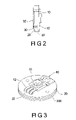
FIG. 2 is a side view of a lighting module according to the present invention;
FIG. 3 is a front view of the lighting module according to the present invention;
FIG. 3A is a front view of another embodiment of the lighting module according to the present invention; and
FIG. 4 is a perspective view of the lighting module according to the present invention.
DETAILED DESCRIPTION OF THE EMBODIMENTS
With respect to FIGS. 2 to 4, a lighting module according to the present invention includes a lighting unit 10 having a lead contact 12, a heat-dissipation plate 20 contacting the lighting unit 10 firmly and an insulative plate 30 disposed under the heat-dissipation plate 20. The heat-dissipation plate 20 has a channel 22 corresponding to the leading contact 12. The insulative plate 30 has a predetermined conductive pattern 32 arranged thereon and a through hole 34 corresponding to the channel 22. The leading contact 12 of the lighting unit 10 penetrates through the channel 22 of the heat-dissipation plate 20 and the through hole 34 of the insulative plate 30 to electrically connect to the predetermined conductive pattern 32 of the insulative plate 32. Therefore, the lighting module can be treated as a whole modulized device with improved efficiency and can be used as a flashlight or another apparatus, in order to avoid the conventional secure structure that is complicated and difficult to assemble.
In addition, the heat-dissipation plate 20 contacts the lighting unit 10 firmly, a contact area being formed therebetween is determined by the sizes thereof. This contact area is different from the contact portion between the aluminum ring 21 a and the metallic plate 133 a, because it transfers heat and is more efficient.
In addition, the lighting unit 10, the heat-dissipation plate 20 and the insulative plate 30, which are assembled as a whole module, can be used to increase the heat dissipation efficiency without other components, such as the conventional lighting unit 15 a, the polypropylene plate 132 a, the metallic plate 133 a, the aluminum ring 21 aand the aluminum sleeve 2 a, to reduce production costs.
The lead contact 12 of the lighting unit 10 can be folded to conduct the heat away from predetermined conductive pattern 32 of the insulative plate 30. Thus, the polypropylene plate 132 a and the metallic plate 133 a provided in the prior art were costly and excessively large.
The lighting unit 10 can include either an LED or a bulb. The lighting unit 10 can be fastened to the heat-dissipation plate 20 via screw 40.
The heat-dissipation plate 20 is a metallic plate made of copper or aluminum or an alloy comprised partly of copper or aluminum. In FIG. 3, a predetermined distance between the channel 22 of the heat-dissipation plate 20 and the lighting unit 10 is provided, and the lead contact 12 extends outwardly along the predetermined distance h and folds downwardly to penetrate the channel 22. Referring to FIG. 3A, the heat-dissipation plate 20 is adjacent to the lighting unit 10, and the leading contact 12 extends downwardly to penetrate the channel 22.
The heat-dissipation plate 20 further includes exterior screw threads (200) to enable the heat-dissipation plate 20 to be firmly attached to the flashlight or other illumination devices.
The insulative plate 30 is made of polypropylene materials.
According to the present invention, the advantages of the light module are:
1. The lighting module can be assembled easily and rapidly.
2. The lighting module has a large heat dissipation area and improves the efficiency of heat dissipation.
3. The lighting module has fewer components and a lower cost.
It should be apparent to those skilled in the art that the above description is only illustrative of specific embodiments and examples of the invention. The invention therefore covers various modifications and variations made to the herein-described structure and operations of the invention, provided they fall within the scope of the invention as defined in the following appended claims.