US7253968B2 - Optical pickup device, optical information recording and reproducing apparatus and objective lens - Google Patents
Optical pickup device, optical information recording and reproducing apparatus and objective lens Download PDFInfo
- Publication number
- US7253968B2 US7253968B2 US10/821,940 US82194004A US7253968B2 US 7253968 B2 US7253968 B2 US 7253968B2 US 82194004 A US82194004 A US 82194004A US 7253968 B2 US7253968 B2 US 7253968B2
- Authority
- US
- United States
- Prior art keywords
- plastic lens
- lens
- objective lens
- plastic
- optical
- Prior art date
- Legal status (The legal status is an assumption and is not a legal conclusion. Google has not performed a legal analysis and makes no representation as to the accuracy of the status listed.)
- Expired - Fee Related, expires
Links
Images


Classifications
-
- G—PHYSICS
- G11—INFORMATION STORAGE
- G11B—INFORMATION STORAGE BASED ON RELATIVE MOVEMENT BETWEEN RECORD CARRIER AND TRANSDUCER
- G11B7/00—Recording or reproducing by optical means, e.g. recording using a thermal beam of optical radiation by modifying optical properties or the physical structure, reproducing using an optical beam at lower power by sensing optical properties; Record carriers therefor
- G11B7/12—Heads, e.g. forming of the optical beam spot or modulation of the optical beam
- G11B7/135—Means for guiding the beam from the source to the record carrier or from the record carrier to the detector
- G11B7/1392—Means for controlling the beam wavefront, e.g. for correction of aberration
- G11B7/13922—Means for controlling the beam wavefront, e.g. for correction of aberration passive
-
- E—FIXED CONSTRUCTIONS
- E04—BUILDING
- E04F—FINISHING WORK ON BUILDINGS, e.g. STAIRS, FLOORS
- E04F17/00—Vertical ducts; Channels, e.g. for drainage
-
- E—FIXED CONSTRUCTIONS
- E03—WATER SUPPLY; SEWERAGE
- E03C—DOMESTIC PLUMBING INSTALLATIONS FOR FRESH WATER OR WASTE WATER; SINKS
- E03C1/00—Domestic plumbing installations for fresh water or waste water; Sinks
- E03C1/02—Plumbing installations for fresh water
-
- E—FIXED CONSTRUCTIONS
- E03—WATER SUPPLY; SEWERAGE
- E03C—DOMESTIC PLUMBING INSTALLATIONS FOR FRESH WATER OR WASTE WATER; SINKS
- E03C2201/00—Details, devices or methods not otherwise provided for
- E03C2201/60—Reducing noise in plumbing systems
-
- G—PHYSICS
- G11—INFORMATION STORAGE
- G11B—INFORMATION STORAGE BASED ON RELATIVE MOVEMENT BETWEEN RECORD CARRIER AND TRANSDUCER
- G11B7/00—Recording or reproducing by optical means, e.g. recording using a thermal beam of optical radiation by modifying optical properties or the physical structure, reproducing using an optical beam at lower power by sensing optical properties; Record carriers therefor
- G11B7/12—Heads, e.g. forming of the optical beam spot or modulation of the optical beam
- G11B7/135—Means for guiding the beam from the source to the record carrier or from the record carrier to the detector
- G11B7/1372—Lenses
- G11B2007/13727—Compound lenses, i.e. two or more lenses co-operating to perform a function, e.g. compound objective lens including a solid immersion lens, positive and negative lenses either bonded together or with adjustable spacing
Definitions
- the present invention relates to an optical pickup device, an optical information recording and reproducing apparatus and an objective lens.
- NA numerical aperture
- an objective lens having image-side numerical aperture NA of about 0.85 is needed for achieving high density.
- a plastic lens is mainly used for the reasons that the plastic lens is light in weight, and it can be manufactured at low cost on a mass production basis through injection molding that employs a mould. Therefore, even in the case of an optical pickup device for a high density optical disc, it is preferable to use a plastic lens as an objective lens for the same reasons.
- an objective lens is generally moved by an actuator in the direction of an optical axis and in the radial direction of a disc for conducting focusing and tracking.
- an electric current is made to flow through a focusing coil and a tracking coil which institute an actuator, and electromagnetic force thus generated between a magnet and the coil is used to move the objective lens.
- a temperature in the optical pickup device is changed under the condition that uneven temperature distribution is caused in the objective lens, spherical aberration of the high NA plastic lens is changed greatly, and recording/reproducing of information for the high density optical disc is obstructed.
- the reason for the foregoing is that deterioration of spherical aberration caused by temperature is extreme even when compared with a lens wherein temperature distribution is substantially even, and a difference of refractive index further grows greater in proportion to the fourth power of NA, because the refractive index is as great as 10 times in comparison especially with a glass lens.
- An object of the invention is to provide an optical pickup device wherein the aforementioned problem is solved, deterioration of spherical aberration is small, and stable recording/reproducing of information can be conducted for high density discs, even in the case where temperature in the optical pickup device is changed under the condition that uneven temperature distribution is caused in the objective lens that is composed of two plastic lenses.
- optical pickup device wherein an amount of changes of spherical aberration in the case of changes of temperature in the optical pickup device is small even in the case where an amount of electric current flowing through a focusing coil and a tracking coil is large, and stable recording/reproducing of information for high density optical discs can be conducted accordingly, and to provide an optical information recording and reproducing apparatus employing the aforesaid optical pickup device.
- An object of the invention is to provide an optical pickup device wherein the aforementioned problems are taken into consideration, an amount of changes of astigmatism in the case where temperature distribution that is non-rotational-symmetry about an optical axis is caused in the objective lens composed of two plastic lenses is small, and recording/reproducing of information can be conducted stably for high density optical discs, and to provide an optical information recording and reproducing apparatus employing the optical pickup device stated above.
- the structure described in Item 1 - 1 is an optical pickup device having therein a light source that emits a light flux having wavelength ⁇ , an objective lens composed of at least two plastic lenses including a first plastic lens having positive refracting power and a second plastic lens having positive refracting power, and an actuator that drives the objective lens wherein temperature distribution in the objective lens is changed to be uneven by heat generated when energizing the actuator, and the following expression (1-1) is satisfied by the objective lens when ⁇ 3SA ( ⁇ RMS) represents a rate of change of the tertiary (third order) spherical aberration of the objective lens, and f (mm) and m respectively represent a focal length of the objective lens for the light flux having wavelength ⁇ and magnification of an optical system.
- the structure described in Item 2 - 1 is an optical pickup device equipped with an objective lens composed of a light source emitting a light flux having wavelength ⁇ and of at least two of a first plastic lens having positive refractive power and a second plastic lens having positive refractive power, wherein temperature distribution in the objective lens is made to be uneven by heat generated when the actuator is energized, and the following expression (2-1) is satisfied when f (mm) represents a focal length of the objective lens, and d 1 (mm) represents a distance between the optical surface on the light source side of the first plastic lens and the optical surface on the optical information recording medium side of the first plastic lens on the optical axis. 0.6 ⁇ d 1 /f ⁇ 1.2 (2-1)
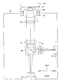
- FIG. 1 is a top view of primary portions showing the structure of an optical pickup device.
- FIG. 2 is a side view of primary portions showing the structure of an objective lens.
- FIG. 3( a ) is a top view of primary portions and FIG. 3( b ) is a longitudinal sectional view of primary portions, both showing the structure of an actuator.
- FIG. 4 shows graphs showing temperature characteristics in the case of giving a linear temperature distribution in the optical axis direction to an objective lens.
- FIG. 5 shows graphs showing temperature characteristics in the case of giving secondary temperature distribution in the radial direction to an objective lens.
- FIG. 6 shows front view (a), side view (b) and rear view (c) all of an objective lens for illustrating “uneven temperature distribution”.
- FIG. 7 shows graphs showing a relationship between TR and astigmatism in an objective lens in Inventive Examples 2-1 to 2-3 and Comparative Example.
- first plastic lens L 1 and second plastic lens L 2 both constituting objective lens OBJ have respectively first flange portion FL 1 and second flange portion FL 2 each being formed solidly with an optical functional portion, on a peripheral portion that is outside the optical functional portion (hatched portion in FIG. 5) , and the first plastic lens L 1 and the second plastic lens L 2 are integrated solidly by joining a part of the first flange portion and a part of the second flange portion (joining portion M in FIG. 6( b )) together.
- T 1 represents temperature of vertex P 1 of the first surface (an optical surface on the light source side of the first plastic lens L 1 ) in the course of driving an actuator (in the course of energizing the actuator)
- T 2 represents temperature of vertex P 2 of the fourth surface (an optical surface on the optical disc side of the second plastic lens L 2 )
- T 3 ° C.
- T 4 ° C.
- T 5 ° C.
- T 6 ° C.
- T 1 -T 6 are assumed to be measured after the temperature distribution change in the objective lens in the course of energizing the actuator becomes to be in a stationary state.
- TA >1.0° C. (R1)
- an occasion where temperature of the total objective lens is changed evenly means an occasion wherein the temperature distribution TA in the optical axis direction and temperature distributions in the radial directions TR 1 and TR 2 satisfy all of the three conditions (R1)-(R3).
- ⁇ 3SA rate of change ⁇ 3SA ( ⁇ RMS) of the tertiary spherical aberration of the objective lens in the case where temperature of the total objective lens is changed evenly
- ⁇ 3SA rate of change ⁇ 3SA ( ⁇ RMS) of the tertiary spherical aberration of the objective lens in the case where temperature of the total objective lens is changed evenly
- 3SA ( ⁇ RMS) represents a tertiary spherical aberration components of wavefront aberration measured under the condition where the change of temperature distribution in the objective lens becomes to be in a stationary state in ambient temperature of 25° C.
- 3SA′ ( ⁇ RMS) represents a tertiary spherical aberration components of wavefront aberration measured under the condition where the change of temperature distribution in the objective lens becomes to be in a stationary state in ambient temperature of 55° C.
- change of temperature distribution in the objective lens becomes to be in a stationary state means that an absolute value of a rate of temperature change is within 0.1° C./min at all measurement points of P 1 -P 6 (see FIG. 6 ).
- focal length f (mm) of the objective lens for a light flux having wavelength ⁇ is assumed to be a focal length obtained through measurement under the ambient temperature of 25° C.
- the invention can be applied to a high density optical disc as an optical information recording medium, and as a high density optical disc, there are given an optical disc with protective base board thickness of about 0.1 mm employing a violet semiconductor laser light source with wavelength of about 400 nm and an objective lens whose numerical aperture NA is raised to about 0.85, and an optical disc with protective base board thickness of about 0.6 mm employing a violet semiconductor laser light source with wavelength of about 400 nm and an objective lens whose numerical aperture NA is raised to about 0.65.
- an objective lens so that ⁇ 0.0003 ⁇ 3SA/(NA4 ⁇ f (1 ⁇ m)) ⁇ 0.0003 may be satisfied.
- a change (deterioration) it is possible to control a change (deterioration) to be small for spherical aberration in the case where temperature in an optical pickup device is changed under the condition that a focusing coil and a tracking coil are energized with high-current.
- the structure described in Item 1 - 2 is represented by the optical pickup device described in Item 1 - 1 wherein the objective lens satisfies the expression (1-1) stated above to control spherical aberration changes in the case where ambient temperature of the optical pickup device is changed in the course of energizing the actuator.
- the structure described in Item 1 - 3 is represented by the optical pickup device described in Item 1 - 1 or Item 1 - 2 wherein at least one of
- Item 1 - 4 The structure described in Item 1 - 4 is represented by the optical pickup device described in either one of Item 1 - 1 -Item 1 - 3 wherein numerical aperture NA on the image side of the objective lens is made to be 0.8 or more.
- Item 1 - 4 In the structure described in Item 1 - 4 , the same effect as that in either one of Item 1 - 1 -Item 1 - 3 can be obtained, and an optical pickup device can be applied properly on a high density optical disc having protective base board thickness of about 0.1 mm employing a violet semiconductor laser light source with wavelength of about 400 nm and an objective lens having numerical aperture NA of about 0.85 on the image side.
- the structure described in Item 1 - 5 is represented by the optical pickup device described in either one of Item 1 - 1 -Item 1 - 4 wherein the actuator is provided at least with a coil for focusing and a coil for tracking, and at least one of the coil for focusing and the coil for tracking is arranged to be positioned so that its center of gravity may be positioned to be closer to the light source than the center of gravity of the second plastic lens is.
- Item 1 - 6 The structure described in Item 1 - 6 is represented by the optical pickup device described in either one of Item 1 - 1 -Item 1 - 5 wherein the following expressions (1-2)-(1-4) are satisfied when ⁇ NL 1 represents a rate of change of refractive index of the first plastic lens for temperature changes,
- ⁇ NL 2 represents a rate of change of refractive index of the second plastic lens for temperature changes
- fB (mm) represents a back focus of the objective lens.
- Item 1 - 7 The structure described in Item 1 - 7 is represented by the optical pickup device described in either one of Item 1 - 1 -Item 1 - 6 wherein the following expression (1-5) is satisfied when f 1 (mm) represents a focal length of the first plastic lens for the light flux having wavelength ⁇ , m 1 represents an optical system magnification of the first plastic lens, f 2 (mm) represents a focal length of the second plastic lens for the light flux having wavelength ⁇ and m 2 represents an optical system magnification of the second plastic lens. 3.5 ⁇ f 1 ⁇ (1 ⁇ m 1)/( f 2 ⁇ (1 ⁇ m )) ⁇ 5.8 (1-5)
- the structure described in Item 1 - 8 is represented by the optical pickup device described in either one of Item 1 - 1 -Item 1 - 7 wherein the first plastic lens has a first flange portion on a peripheral portion that is outside the optical functional portion and the second plastic lens has a second flange portion on a peripheral portion that is outside the optical functional portion, and the first plastic lens and the second plastic lens are integrated solidly by joining a part of the first flange portion and a part of the second flange portion together, and when D 1 (mm) represents an outside diameter of the first plastic lens including the first flange portion and D 2 (mm) represents an outside diameter of the second plastic lens including the second flange portion, the following expression (1-6) is satisfied and the first plastic lens is held by a bobbin that is driven by the actuator. D1>D2 (1-6)
- the first plastic lens is arranged at the position that is closer to the focusing coil and the tracking coil which generate heat when the optical pickup device is operating, which causes troubles that uneven temperature distribution tends to be caused in the objective lens.
- the optical pickup device of the first embodiment it is possible to control changes of spherical aberration caused by unevenness of temperature distribution in the objective lens to be small when temperatures in the optical pickup device are changed, because the objective lens is designed so that the expression (1-1) is satisfied, thus, stable recording/reproducing of information can be conducted for high density optical discs.
- the optical information recording and reproducing apparatus described in Item 1 - 9 is equipped with the optical pickup device described in either one of Item 1 - 1 -Item 1 - 8 , and can conduct at least one of recording information on the optical information recording medium and reproducing information recorded on the optical information recording medium.
- the structure described in Item 1 - 10 is an objective lens for an optical pickup device composed of at least two plastic lenses including a first plastic lens having positive refracting power and a second plastic lens having positive refracting power, wherein the objective lens satisfies the following expression (1-1) when ⁇ 3SA ( ⁇ RMS) represents a rate of change of the tertiary spherical aberration of the objective lens in the case where temperature of the total objective lens is changed evenly, and f (mm) and m respectively represent a focal length of the objective lens for the light flux having wavelength ⁇ and magnification of an optical system, and thereby, a change of spherical aberration in the case where ambient temperature of the optical pickup device is changed is controlled, under the condition that temperature distribution in the objective lens is changed to be uneven by heat generated when energizing the actuator that drives the objective lens.
- the structure described in Item 1 - 11 is an objective lens described in Item 1 - 10 wherein the following expression (1-7) is satisfied. ⁇ 0.0003 ⁇ 3 SA /( NA 4 ⁇ f ⁇ (1 ⁇ m )) ⁇ 0.0003 (1-7)
- Item 1 - 11 In the structure described in Item 1 - 11 , the same effect as that in Item 1 - 10 can be obtained, and it is possible to control a change (deterioration) of spherical aberration to be small in the case where temperature in the optical pickup device is changed under the condition that the focusing coil and the tracking coil are energized with high-current.
- the structure described in Item 1 - 12 is represented by the objective lens described in Item 1 - 10 or Item 1 - 11 wherein at least one of
- Item 1 - 13 The structure described in Item 1 - 13 is represented by the objective lens described in either one of Item 1 - 10 -Item 1 - 12 wherein numerical aperture NA on the image side is made to be 0.8 or more.
- the same effect as that in either one of Item 1 - 10 -Item 1 - 12 can be obtained, and the first embodiment can be used properly for a high density optical disc having protective base board thickness of about 0.1 mm and using a violet semiconductor laser light source with wavelength of about 400 nm and an objective lens having numerical aperture NA of about 0.85 on the image side.
- Item 1 - 14 The structure described in Item 1 - 14 is represented by the objective lens described in either one of Item 1 - 10 -Item 1 - 13 wherein the following expressions (1-2)-(1-4) are satisfied when ⁇ NL 1 represents a rate of change of refractive index of the first plastic lens for temperature changes, ⁇ NL 2 represents a rate of change of refractive index of the second plastic lens for temperature changes, and fB (mm) represents a back focus of the objective lens. ⁇ 20 ⁇ 10 ⁇ 5 /° C. ⁇ NL 1 ⁇ 2 ⁇ 10 ⁇ 5 /° C. (1-2) 0.6 ⁇ NL 2 / ⁇ NL 1 ⁇ 1.5 (1-3) 0.1 ⁇ ( ⁇ NL 2 / ⁇ NL 1) ⁇ fB /( f ⁇ (1 ⁇ m )) ⁇ 0.2 (1-4)
- the structure described in Item 1 - 15 is represented by the objective lens wherein the following expressions (1-8)-(1-10) are satisfied. ⁇ 15 ⁇ 10 ⁇ 5 /° C. ⁇ NL 1 ⁇ 5 ⁇ 10 ⁇ 5 /° C. (1-8) 0.7 ⁇ NL 2 / ⁇ NL 1 ⁇ 1.4 (1-9) 0.12 ⁇ ( ⁇ NL 2 / ⁇ NL 1) ⁇ fB /( f ⁇ (1 ⁇ m )) ⁇ 0.18 (1-10)
- Item 1 - 15 In the structure described in Item 1 - 15 , the same effect as that in Item 1 - 14 can be obtained, and it is possible to control a change (deterioration) to be small for spherical aberration in the case where temperature in the optical pickup device is changed, even in the case where an amount of energizing for the focusing coil and the tracking coil grows greater.
- Item 1 - 16 The structure described in Item 1 - 16 is represented by the objective lens described in either one of Item 1 - 10 -Item 1 - 15 wherein the following expression (1-5) is satisfied when f 1 (mm) represents a focal length of the first plastic lens for the light flux having wavelength ⁇ , m 1 represents an optical system magnification of the first plastic lens, f 2 (mm) represents a focal length of the second plastic lens for the light flux having wavelength ⁇ and m 2 represents an optical system magnification of the second plastic lens. 3.5 ⁇ f 1 ⁇ (1 ⁇ m 1)/( f 2 ⁇ (1 ⁇ m )) ⁇ 5.8 (1-5)
- Item 1 - 17 The structure described in Item 1 - 17 is represented by the objective lens described in either one of Item 1 - 10 -Item 1 - 16 wherein the second plastic lens is a meniscus that is convex toward the first plastic lens.
- the form of the second plastic lens to be a meniscus that is convex toward the first plastic lens, occurrence of coma can be reduced and a tolerance for positional adjustment of a light source can be relaxed.
- the structure described in Item 1 - 18 is represented by the objective lens described in either one of Item 1 - 10 -Item 1 - 17 wherein the first plastic lens has a first flange portion on a peripheral portion that is outside the optical functional portion and the second plastic lens has a second flange portion on a peripheral portion that is outside the optical functional portion, and the first plastic lens and the second plastic lens are integrated solidly by joining a part of the first flange portion and a part of the second flange portion together, and when D 1 (mm) represents an outside diameter of the first plastic lens including the first flange portion and D 2 (mm) represents an outside diameter of the second plastic lens including the second flange portion, the following expression (1-6) is satisfied and the first plastic lens is held by a bobbin that is driven by the actuator. D1>D2 (1-6)
- the first plastic lens is arranged at the position that is closer to the focusing coil and the tracking coil which generate heat when the optical pickup device is operating, which causes troubles that uneven temperature distribution tends to be caused in the objective lens.
- FIG. 1 is a schematic diagram of optical pickup device PU of the present embodiment, and the optical pickup device PU is composed of violet semiconductor laser LD representing a light source emitting a light flux with wavelength ⁇ , polarized beam splitter BS, collimator CL, 1 ⁇ 4 wavelength plate WP, diaphragm ST, objective lens OBJ, biaxial actuator AC, cylindrical lens CY, concave lens NL, and photo-detector PD.
- the direction running parallel with the optical axis direction toward a light source is sometimes expressed as “front” for convenience' sake, and the direction toward an optical information recording medium is expressed as “the rear”.
- a divergent light flux with wavelength ⁇ emitted from the violet semiconductor laser LD is transmitted through the polarized beam splitter BS, and after becoming a circularly polarized collimated light flux through the collimator lens CL and 1 ⁇ 4 wavelength plate WP, a diameter of the light flux is regulated by the diaphragm ST, and the light flux becomes a spot formed by the objective lens OBJ on information recording surface RL through protective layer PL of high density optical disc OD.
- a reflected light flux modulated by information pits on the information recording surface RL passes through the objective lens OBJ, the diaphragm ST, 1 ⁇ 4 wavelength plate WP and collimator lens CL again to become a converged light flux, then, reflected by the polarized beam splitter BS, and passes through the cylindrical lens CY and concave lens NL to be given astigmatism, and is converged on the photo-detector PD.
- information recorded on optical disc OD can be read by the use of output signals of the photo-detector PD.
- the objective lens OBJ has a function to converge a laser beam emitted from the violet semiconductor laser LD on information recording surface RL of high density optical disc OD through its protective layer PL.
- the objective lens OBJ is a plastic lens of a two-group structure type composed of first plastic lens L 1 having positive power (refracting power) arranged to be closer to the violet semiconductor laser LD and second plastic lens L 2 having positive power arranged to be closer to high density optical disc OD, and image-side numerical aperture NA obtained by combining the aforementioned two plastic lenses is 0.85.
- objective lens OBJ used in the first embodiment it has only to be of a plastic lens structure with at least two groups, and it is not limited to the structure with only two groups shown in the present embodiment.
- first plastic lens L 1 and second plastic lens L 2 both have respectively first flange portion FL 1 and second flange portion FL 2 each being formed solidly with an optical functional portion, on a peripheral portion rather than the optical functional portion (hatched portion in FIG. 2 ), and the first plastic lens L 1 and the second plastic lens L 2 are integrated solidly by joining a part of the first flange portion FL 1 and a part of the second flange portion FL 2 (joining portion M in FIG. 2( b )) together.
- Outside diameter D 1 (mm) of the first plastic lens L 1 including the first flange portion FL 1 is greater than outside diameter D 2 (mm) of the second plastic lens L 2 including the second flange portion FL 2 , to satisfy the expression (1-6) mentioned above.
- a volume of the first plastic lens L 1 arranged to be closer to the light source is greater than that of the second plastic lens L 2 , and driving accuracy (positioning accuracy) by actuator AC for objective lens OBJ that is in the state of being held by bobbin B can be improved, as stated later.
- FIGS. 3( a ) and 3 ( b ) are detailed drawings in the vicinity of objective lens OBJ.
- the objective lens OBJ is held by bobbin B driven by biaxial actuator AC when the first flange portion FL 1 of the first plastic lens L 1 touches.
- biaxial actuator AC will be omitted here because they are known widely.
- the symbol MG represents a magnet.
- focusing coil FC and tracking coil TC are arranged to be front of the rear end of objective lens OBJ (plane of emergence of the second plastic lens L 2 in the present embodiment) in many cases, and the center of gravity GC of the focusing coil is positioned at a point in the vicinity of the center of a length of that coil in its longitudinal direction, and the center of gravity GC′ of the tracking coil is positioned at a point in the vicinity of the center of a length of that coil in its longitudinal direction.
- center of gravity positions GC and GC′ respectively of the focusing coil FC and the tracking coil TC are positioned to be closer than the center of gravity position GL 2 of the second plastic lens L 2 to violet semiconductor laser LD.
- temperature of objective lens OBJ rises under an influence of heat generated from the focusing coil FC and the tracking coil TC, and temperature on the peripheral portion on the plane of incidence of the first plastic lens L 1 becomes higher than temperature in the vicinity of an optical axis on the plane of emergence of the second plastic lens L 2 , because the focusing coil FC and the tracking coil TC are arranged to be front of the second plastic lens L 2 , thus, uneven temperature distribution is caused in the objective lens OBJ.
- the optical pickup device PU relating to the first embodiment, even when temperature in the optical pickup device PU is changed under the condition that uneven temperature distribution is caused in the objective lens OBJ, changes in spherical aberration can be controlled to be small, because the objective lens OBJ is designed to satisfy the expression (1-1), thus, stable recording/reproducing of information can be conducted for high density optical disc OD.
- f 1 (mm) represents a focal length of the first plastic lens L 1 for a light flux with wavelength ⁇
- m 1 represents optical system magnification of the first plastic lens L 1
- f 2 (mm) represents a focal length of the second plastic lens L 2 for a light flux with wavelength ⁇
- m 2 represents optical system magnification of the second plastic lens L 2 .
- objective lens OBJ so that ⁇ 0.0003 ⁇ 3SA/(NA4 ⁇ f ⁇ (1 ⁇ m)) ⁇ 0.0003 (expression (1-7)) may be satisfied, and to design so that ⁇ 15 ⁇ 10 ⁇ 5 /° C. ⁇ NL 1 ⁇ 5 ⁇ 10 ⁇ 5 /° C. (expression (1-8)), 0.7 ⁇ NL 2 / ⁇ NL 1 ⁇ 1.4 (expression (1-9)) and 0.12 ⁇ ( ⁇ NL 2 / ⁇ NL 1 ) ⁇ fB/(f ⁇ (1 ⁇ m)) ⁇ 0.18 (expression (1-10)) may be satisfied.
- the second plastic lens L 2 is a meniscus that is convex toward the first plastic lens L 1 .
- the objective lens made of plastic having high NA of a two-group structure if its form is designed so that the expression (1-4) is satisfied, coma caused on a final surface (an optical surface that is closest to an optical information recording medium) is large, in general, when a light flux having a field angle enters the objective lens, which makes a tolerance for positional adjustment of a light source to be severe.
- occurrence of the coma can be reduced and tolerance for positional adjustment for the light source can be relaxed.
- optical information recording and reproducing apparatus which is provided with the optical pickup device PU, a rotary driving device that holds optical information recording medium OD rotatably and a control device that controls driving of the various devices stated above, and conducts at least one of recording of information for optical information recording medium OD and reproducing of information recorded on optical information recording medium OD.
- Lens data of a plastic lens with NA of 0.85 designed so that a value of the expression (1-1) may be zero are shown in Table 1-1 as Example 1-1
- lens data of a plastic lens with NA of 0.85 designed so that a value of ⁇ 3SA/(NA 4 ⁇ f ⁇ (1 ⁇ m)) may be 0.0004, namely the expression (1-1) may not be satisfied are shown in Table 1-2 as Comparative Example 1-1
- lens data of a plastic lens with NA of 0.85 designed so that a value of ⁇ 3SA/(NA 4 ⁇ f ⁇ (1 ⁇ m)) may be ⁇ 0.0004, namely, the expression (1-1) may not be satisfied are shown in Table 1-3 as Comparative Example 1-2.
- focal length f for wavelength ⁇ (405 nm) is 1.765 mm
- optical system magnification m is 0, each of rate of change ⁇ NL 1 of the refractive index of the first plastic lens L 1 for temperature changes and rate of change ⁇ NL 2 of the refractive index of the second plastic lens L 2 for temperature changes is ⁇ 11 ⁇ 10 ⁇ 5 /° C.
- outside diameter D 1 of the first plastic lens L 1 including first flange portion FL 1 is 4.8 mm
- outside diameter D 2 of the second plastic lens L 2 including second flange portion FL 2 is 3.8 mm.
- NA represents a numerical aperture
- ⁇ (nm) is a design wavelength
- f (mm) represents a focal length
- m represents an optical system magnification
- r (mm) represents a radius of curvature
- d (mm) represents a distance between surfaces
- N ⁇ represents a refractive index in the design wavelength
- ⁇ d represents Abbe's number in d line
- an aspheric surface is expressed by the following Numeral 1 when X (mm) represents an amount of deformation from a plane that is tangent to the aspheric surface at its vertex
- h (mm) represents a height in the direction perpendicular to the optical axis and
- r (mm) represents a radius of curvature
- ⁇ represents a conic constant
- a 2i represents an aspheric surface coefficient.
- focal length f 1 (mm) of the first plastic lens L 1 for a light flux having wavelength ⁇ is 4.87 mm
- optical system magnification m 1 of the first plastic lens L 1 is 0
- focal length f 2 (mm) of the second plastic lens L 2 for a light flux having wavelength ⁇ is 1.65 mm
- optical system magnification m 2 of the second plastic lens L 2 is 0.37.
- focal length f 1 (mm) is 4.87 mm
- optical system magnification m 1 is 0, focal length f 2 (mm) is 1.70 mm
- optical system magnification m 2 is 0.35
- focal length f 1 (mm) is 4.65 mm
- optical system magnification m 1 is 0, focal length f 2 (mm) is 1.64 mm
- optical system magnification m 2 is 0.36.
- FIG. 4 shows results obtained through simulation of temperature characteristics wherein refractive index distribution corresponding to temperature distribution in the optical axis direction caused in objective lens OBJ by heat generated in focusing coil FC and tracking coil TC is given to a plastic lens of each of Example 1 and Comparative Examples 1 and 2.
- a linear temperature distribution wherein temperature falls gradually in the direction from the light source side to the optical disc side is assumed as a model of temperature distribution in the optical axis direction, and with respect to the axis of abscissas in FIG. 4 , temperature at a vertex (P 2 in FIG. 6 ) of the optical surface on the optical disc side of the second plastic lens L 2 is T 2 .
- “no energizing” corresponds to an occasion where uneven temperature distribution is not caused in objective lens OBJ, and temperature of the total objective lens OBJ rises evenly. Therefore, values of the temperature distribution TA in the optical axis direction and of the temperature distributions TR 1 and TR 2 in the radial directions are all zero, and none of the aforementioned three conditions (R1)-(R3) is satisfied.
- temperature distribution 1 corresponds to an occasion wherein temperature falls by 1° C. for a length of 1 mm from the light source side to the optical disc side. Since the lens thickness on the optical axis in Example 1-1 and in Comparative Examples 1-1 and 1-2 excluding an air distance of 0.05 mm between the first plastic lens L 1 and the second plastic lens L 2 is 3.55 mm, temperature difference TA between temperature at a vertex (P 1 in FIG. 6 ) of the optical surface on the light source side of the first plastic lens L 1 and temperature at a vertex (P 2 in FIG. 6 ) of the optical surface on the optical disc side of the second plastic lens L 2 is 3.55.
- the refractive index at P 1 is lower than that at P 2 by 39.05 ⁇ 10 ⁇ 5 .
- values of temperature distribution TA in the optical axis direction in “temperature distribution 1” and of temperature distributions in the radial directions TR 1 and TR 1 are respectively 3.55, 1.225 and 2.325.
- temperature distribution 2 corresponds to an occasion wherein temperature falls by 2° C. for a length of 1 mm from the light source side to the optical disc side, and temperature difference TA between temperature at a vertex P 1 of the optical surface on the light source side of the first plastic lens L 1 and temperature at a vertex P 2 of the optical surface on the optical disc side of the second plastic lens L 2 is 7.10. Therefore, the refractive index at P 1 is lower than that at P 2 by 78.1 ⁇ 10 ⁇ 5 .
- values of temperature distribution TA in the optical axis direction at “temperature distribution 2” and of temperature distributions in the radial directions TR 1 and TR 2 are respectively 7.10, 2.45 and 4.65.
- FIG. 5 shows results obtained through simulation of temperature characteristics wherein refractive index distribution corresponding to temperature distribution in the radial direction caused in objective lens OBJ by heat generated in focusing coil FC and tracking coil TC is given to a plastic lens of each of Example 1-1 and Comparative Examples 1-1 and 1-2.
- secondary temperature distribution in the radial direction wherein temperature rises gradually in the direction from the optical axis to the peripheral portion (which is rotational symmetry about an optical axis) is assumed as a model of temperature distribution in the optical axis direction, and the axis of abscissas in FIG. 5 represents temperature on the optical axis of the objective lens.
- “no energizing” corresponds to an occasion where uneven temperature distribution is not caused in objective lens OBJ, and temperature of the total objective lens OBJ rises evenly. Therefore, values of the temperature distribution TA in the optical axis direction and of the temperature distributions TR 1 and TR 2 in the radial directions are all zero, and none of the aforementioned three conditions (R1)-(R3) is satisfied.
- temperature distribution 1 corresponds to an occasion wherein the secondary coefficient of temperature distribution in the radial direction is ⁇ 3.82 ⁇ 10 ⁇ 5 , and this corresponds to an occasion wherein temperature on the outermost position (position at diameter 4.8) of the first plastic lens L 1 including first flange portion FL 1 is higher than temperature on the optical axis by 2° C.
- the refractive index at each of P 3 -P 6 is lower than that in each of P 1 and P 2 by 22.0 ⁇ 10 ⁇ 5 .
- values of the temperature distribution TA in the optical axis direction and of the temperature distributions TR 1 and TR 2 in the radial directions are respectively 0, 2 and 2, and all of the aforementioned three conditions (R1)-(R3) are satisfied.
- temperature distribution 2 corresponds to an occasion wherein the secondary coefficient of temperature distribution in the radial direction is ⁇ 7.64 ⁇ 10 ⁇ 5 , and this corresponds to an occasion wherein temperature on the outermost position (position at diameter 4.8) of the first plastic lens L 1 including first flange portion FL 1 is higher than temperature on the optical axis by 4° C.
- the refractive index at each of P 3 -P 6 is lower than that in each of P 1 and P 2 by 44.0 ⁇ 10 ⁇ 5 .
- values of the temperature distribution TA in the optical axis direction and of the temperature distributions TR 1 and TR 2 in the radial directions are respectively 0, 4 and 4, and all of the aforementioned three conditions (R1)-(R3) are satisfied.
- an ambient temperature of optical pickup device PU is 25° C. at the start of recording/reproducing in optical pickup device PU equipped with the objective lens OBJ in Example 1-1 and in Comparative Example 1-2 (therefore, temperature at vertex P 2 on the optical surface on the optical disc side of the second plastic lens L 2 is 25° C., and temperature distribution TA in the optical axis is zero), and temperature on vertex P 2 on the optical surface on the optical disc side of the second plastic lens L 2 at completion of recording/reproducing is 65° C., following upon a rise in ambient temperature for the optical pickup device PU, and temperature distribution in the optical axis direction given by “temperature distribution 2” in FIG. 4 is caused in objective lens OBJ by an influence of heat generation of actuator AC.
- an amount of change of wavefront aberration at completion of recording/reproducing for that at the start of recording/reproducing is about 0.04 ⁇ RMS in the objective lens in Comparative Example 2 that does not satisfy expression (1-1), and understood, from FIG. 4( a ), that an amount of change of wavefront aberration at completion of recording/reproducing for that at the start of recording/reproducing is controlled to be as small as about 0.03 ⁇ RMS or less in the objective lens OBJ in Example 1 that satisfies expression (1-1).
- an ambient temperature of optical pickup device PU is 25° C. at the start of recording/reproducing in optical pickup device PU equipped with the objective lens in Example 1 and in Comparative Example 1 (therefore, temperature on the optical axis of the objective lens is 25° C., and temperature distributions in the radial direction TR 1 and TR 2 are zero), and temperature on the optical axis of objective lens is 65° C., following upon a rise in ambient temperature for the optical pickup device PU, and temperature distribution in the radial direction given by “temperature distribution 2” in FIG. 5 is caused in the objective lens by an influence of heat generation of actuator AC.
- an amount of change of wavefront aberration at completion of recording/reproducing for that at the start of recording/reproducing is about 0.04 ⁇ RMS in the objective lens in Comparative Example 1 that does not satisfy expression (1-1), and understood, from FIG. 5( a ), that an amount of change of wavefront aberration at completion of recording/reproducing for that at the start of recording/reproducing is controlled to be as small as about 0.03 ⁇ RMS or less in the objective lens OBJ in Example 1 that satisfies expression (1-1).
- the objective lens OBJ in Example 1 it is understood that a change of spherical aberration is controlled to be small, and there are provided sufficient functions as an objective lens used in an optical pickup device for a high density optical disc for which an allowable range for wavefront aberration of objective lens OBJ is severe, even in the case where ambient temperature for optical pickup device PU is changed under the condition that uneven temperature distribution in the objective lens OBJ is caused by an influence of heat generation of actuator AC.
- An objective lens in Example 2 whose lens data are shown in Table 1-4 is a plastic lens having NA of 0.85 that is designed sot that a value of ⁇ 3SA/(NA 4 ⁇ f ⁇ (1 ⁇ m)) may be ⁇ 0.0002, and its focal length f for wavelength ⁇ (405 nm) is 1.765 mm, optical system magnification m is 0, rate of change ⁇ NL 1 of refractive index of first plastic lens L 1 for temperature changes is ⁇ 11 ⁇ 10 ⁇ 5 /° C., rate of change ⁇ NL 2 of refractive index of second plastic lens L 2 for temperature changes ⁇ 9 ⁇ 10 ⁇ 5 /° C., outside diameter D 1 of first plastic lens L 1 including first flange portion FL 1 is 4.8 mm and outside diameter D 2 of second plastic lens L 2 including second flange portion L 2 is 3.8 mm.
- objective lens OBJ in Example 1-3 whose lens data are shown in Table 1-5 is a plastic lens having NA of 0.85 that is designed so that a value of ⁇ 3SA/(NA 4 ⁇ f ⁇ (1 ⁇ m)) may be ⁇ 0.0001, and its focal length f for wavelength ⁇ (405 nm) is 1.765 mm, optical system magnification m is ⁇ 0.089, rate of change ⁇ NL 1 of refractive index of first plastic lens L 1 for temperature changes is ⁇ 11 ⁇ 10 ⁇ 5 /° C., rate of change ⁇ NL 2 of refractive index of second plastic lens L 2 for temperature changes is ⁇ 9 ⁇ 10 ⁇ 5 /° C., outside diameter D 1 of first plastic lens L 1 including first flange portion FL 1 is 4.8 mm and outside diameter D 2 of second plastic lens L 2 including second flange portion FL 2 is 3.8 mm.
- focal length f 1 (mm) is 5.38 mm
- optical system magnification m 1 is 0
- focal length f 2 (mm) is 1.60
- optical system magnification m 2 is 0.33
- focal length f 1 (mm) is 3.89 mm
- optical system magnification m 1 is ⁇ 0.11
- focal length f 2 (mm) is 1.73
- optical system magnification m 2 is 0.41.
- both objective lenses OBJ respectively in Examples 1-2 and 1-3 are designed so that the expression (1-1) may be satisfied, even when temperature in optical pickup device PU is changed in the state where temperature distribution is caused in objective lens OBJ, spherical aberration change is small, and the objective lens OBJ has sufficient power as an objective lens in the optical pickup device for a high density optical disc for which an allowable range for wavefront aberration of objective lens OBJ is severe.
- NA represents a numerical aperture
- ⁇ (nm) is a design wavelength
- f (mm) represents a focal length
- m represents an optical system magnification
- r (mm) represents a radius of curvature
- d (mm) represents a distance between surfaces
- N ⁇ represents a refractive index in the design wavelength
- ⁇ d represents Abbe's number in d line
- an aspheric surface is expressed by the following Numeral 1 when X (mm) represents an amount of deformation from a plane that is tangent to the aspheric surface at its vertex
- h (mm) represents a height in the direction perpendicular to the optical axis and
- r (mm) represents a radius of curvature
- ⁇ represents a conic constant
- a 2i represents an aspheric surface coefficient.
- the first embodiment makes it possible to obtain an optical pickup device wherein deterioration of spherical aberration is small, and stable recording/reproducing of information can be conducted for high density optical discs even when temperature in the optical pickup device is changed in the state in which uneven temperature distribution is caused in an objective lens composed of two plastic lenses.
- an optical pickup device wherein an amount of change of spherical aberration in the case of temperature change in an optical pickup device is small, and stable recording/reproducing of information can be conducted for high density optical discs even when an amount of energizing for a focusing coil and a tracking coil grows great, and to obtain an optical information recording and reproducing apparatus employing the aforementioned optical pickup device.
- an objective lens that is composed of two plastic lenses to be suitable as an objective lens for an optical pickup device for high density optical discs, and is excellent in recording/reproducing, even in the case where temperature in the optical pickup device is changed in the state where uneven temperature distribution is caused in the objective lens.
- “uneven temperature distribution” means that when driving an actuator (not shown) (when energizing a coil), under the assumption that T 1 (° C.) represents temperature of vertex P 1 of the first surface (an optical surface on the light source side of the first plastic lens L 1 ), T 2 (° C.) represents temperature of vertex P 2 of the fourth surface (an optical surface on the optical recording medium side of the second plastic lens L 2 ), and T 3 (° C.), T 4 (° C.), T 5 (° C.) and T 6 (° C.) represent temperatures respectively at points P 3 , P 4 , P 5 and P 6 where optional line CL that passes through the middle point of a lens thickness (thickness on an optical axis) of the first plastic lens L 1 and is perpendicular to the optical axis and line CL′ representing the line CL rotated by 90° intersect an outer circumference of the first flange portion FL 1 , and when TH represents the highest temperature among T 3 -T 6 , TL represents the lowest temperature and
- temperature distribution in the objective lens is even means an occasion where both expressions (2-3) and (2-4) are not satisfied simultaneously.
- a height of passing of marginal ray of light for the first plastic lens arranged at the light source side is higher than that for the second plastic lens arranged on the optical information recording medium side. Therefore, a ray of light with NA of 0.85 is easily affected by distribution of refractive index following upon temperature distribution.
- the structure described in Item 2 - 2 is the optical pickup device according to Item 2 - 1 , wherein the following expression (2-1′) is satisfied. 0.6 ⁇ d 1 /f ⁇ 0.92 (2-1′)
- first plastic lens L 1 and second plastic lens L 2 both constituting objective lens OBJ have respectively first flange portion FL 1 and second flange portion FL 2 each being formed solidly with each optical functional portion, on the peripheral portion that is outside the optical functional portion (hatched portion in FIG. 5) , and the first plastic lens L 1 and the second plastic lens L 2 are integrated solidly by joining a part of the first flange portion and a part of the second flange portion (joining portion M in FIG. 5( b )) together.
- the structure described in Item 2 - 3 is an optical pickup device having therein a light source that emits a light flux with wavelength ⁇ , an objective lens made up of at least two plastic lenses including a first plastic lens having a positive refractive power and a second plastic lens having a positive refractive power and an actuator that drives the objective lens, wherein heat generated in the course of energizing the actuator makes temperature distribution in the objective lens to be uneven, and the following expression (2-2) is satisfied when f 1 (mm) represents a focal length of the first plastic lens, ⁇ 1 represents a magnification of the first plastic lens, f 2 (mm) represents a focal length of the second plastic lens and ⁇ 2 represents a magnification of the second plastic lens.
- f 1 (mm) represents a focal length of the first plastic lens
- ⁇ 1 represents a magnification of the first plastic lens
- f 2 (mm) represents a focal length of the second plastic lens
- ⁇ 2 represents a magnification of the second plastic lens.
- the structure described in Item 2 - 4 is the optical pickup device described in Item 2 - 3 wherein the following expression (2-2′) is satisfied. 2.2 ⁇ f 1 ⁇ (1 ⁇ 1)/( f 2 ⁇ (1 ⁇ 2)) ⁇ 4.0 (2-2′)
- f 1 , ⁇ 1 , f 2 and ⁇ 2 it is more preferable to make the relationship of f 1 , ⁇ 1 , f 2 and ⁇ 2 to be within a range of expression (2-2′).
- the structure described in Item 2 - 5 is the optical pickup device according to either one of Items 2 - 1 - 2 - 4 , wherein it is possible to control astigmatism changes caused when temperature distribution in the objective lens becomes uneven in the course of energizing the actuator, when the objective lens satisfies the aforesaid expression (2-1), (2-1′), (2-2) or (2-2′).
- the structure described in Item 2 - 6 is the optical pickup device according to either one of Items 2 - 1 - 2 - 5 , wherein the following expressions (2-3) and (2-4) are satisfied when TP(° C.) represents temperature distribution in the circumferential direction of the objective lens in the course of energizing the actuator, and TRC(° C.) represents temperature distribution in the direction perpendicular to the optical axis.
- TP
- TR
- the structure described in Item 2 - 7 is the optical pickup device according to either one of Items 2 - 1 - 2 - 6 , wherein the following expressions (2-5) is satisfied when d 12 represents a distance between the first plastic lens and the second plastic lens on the optical axis. 0.1 ⁇ d 12 /f ⁇ 0.4 (2-5)
- the structure described in Item 2 - 8 is the optical pickup device according to either one of Items 2 - 1 - 2 - 7 , wherein image-side numerical aperture NA of the objective lens is made to be 0.8 or more.
- the optical pickup device can be used properly for a high density optical disc with a protective layer whose thickness is about 0.1 mm employing a violet semiconductor laser with wavelength of about 400 nm and an objective lens whose image-side numerical aperture NA is about 0.85.
- the structure described in Item 2 - 9 is the optical pickup device according to either one of Items 2 - 1 - 2 - 8 , wherein the actuator is provided with at least a coil for focusing and a coil for tracking, and at least one of the coil for focusing and the coil for tracking is arranged so that the coil may be positioned to be closer in terms of the center of gravity to the light source than the second plastic lens.
- the two-group-structured lens is in a tendency wherein a volume of the first plastic lens is larger, and the center of gravity of the two-group-structured lens is closer to the light source than that of the second plastic lens, thus, focusing and tracking can be conducted stably by making the center of gravity of the focusing coil and that of the tracking coil to be closer to the center of gravity of the second plastic lens.
- the structure described in Item 2 - 10 is the optical pickup device according to either one of Items 2 - 1 - 2 - 9 , wherein the first plastic lens has a first flange portion on a peripheral portion that is outside the optical functional portion and the second plastic lens has a second flange portion on a peripheral portion that is outside the optical functional portion, and the first plastic lens and the second plastic lens are integrated solidly by joining a part of the first flange portion and a part of the second flange portion together, and when D 1 (mm) represents an outside diameter of the first plastic lens including the first flange portion and D 2 (mm) represents an outside diameter of the second plastic lens including the second flange portion, the following expression (2-6) is satisfied and the first plastic lens is held by a bobbin that is driven by the actuator. D1>D2 (2-6)
- a flange is provided on the peripheral portion that is outside the optical functional portion of the plastic lens, and a two-group-structured lens is formed by joining the flanges, which is better in terms of cost and easiness of assembling a two-group-structured lens than making newly the parts for joining.
- the optical functional portion of the first plastic lens is greater than that of the second plastic lens, and therefore, the center of gravity of the objective lens is positioned to be closer to the first plastic lens than to the second plastic lens.
- the structure described in Item 2 - 11 is the optical pickup device according to Item 2 - 10 , wherein the following expression (2-7) is satisfied when E 1 (mm) represents an effective diameter of the light-source-side optical surface of the first plastic lens. 0.4 ⁇ E 1/D1 ⁇ 0.65 (2-7)
- making E 1 and D 1 to be smaller than the upper limit of the expression (2-7) means that a ratio of an effective diameter to an outside diameter of the objective lens is made to be small, and unevenness of temperature distribution in the optical functional portion is reduced.
- astigmatism changes caused by uneven temperature distribution can be controlled effectively by satisfying expressions (2-1) and (2-7) or expressions (2-2) and (2-7). It is further possible to prevent that an outside diameter of the objective lens becomes too large.
- the structure described in Item 2 - 12 is provided with the optical pickup device according to either one of Items 2 - 1 - 2 - 11 , and is capable of conducting at least one of recording of information on the optical information recording medium and reproducing of information recorded on the optical information recording medium.
- Item 2 - 12 makes it possible to manufacture optical information recording and reproducing apparatuses having the effects in either one of Items 2 - 1 - 2 - 11 .
- the structure described in Item 2 - 13 is an objective lens for an optical pickup device composed of at least two of the first plastic lens having positive refracting power and the second plastic lens having positive refracting power, wherein the following expression (2-1) is satisfied when f (mm) represents a focal length of the objective lens and d 1 (mm) represents a distance on the optical axis between the light-source-side optical surface of the first plastic lens and the optical surface on the optical information recording medium side, and thereby, it is possible to control astigmatism changes that is cause when temperature distribution in the objective lens is made to be uneven by heat generation in the course of energizing the actuator that drives the objective lens.
- f (mm) represents a focal length of the objective lens
- d 1 (mm) represents a distance on the optical axis between the light-source-side optical surface of the first plastic lens and the optical surface on the optical information recording medium side
- the structure described in Item 2 - 14 is the optical pickup device according to Item 2 - 13 , wherein the following expression (2-1′) is satisfied. 0.6 ⁇ d 1 /f ⁇ 0.92 (2-1′)
- a degree of transmission of a marginal ray of light is higher in a first plastic lens arranged to be closer to a light source than in a second plastic lens arranged to be closer to a optical information recording medium. Therefore, a ray of light with NA 0.85 tends to be affected by a distribution of refractive index caused by temperature distribution in the first plastic lens.
- the structure described in Item 2 - 12 makes it possible to reduce an influence of refractive index changes caused by temperature distribution under which the ray of light with NA 0.85 comes, by designing the objective lens so that expression (2-1) may be satisfied. Therefore, even in the optical pickup device employing an objective lens made up of a plastic lens that is composed of at least two groups, astigmatism changes on an information recording surface of an optical information recording medium in use can be controlled, and recording/reproducing of information for high density optical discs can be conducted stably.
- an value of d 1 /f it is more preferable to make an value of d 1 /f to be within a range of expression (2-1′) in Item 2 - 14 .
- the structure described in Item 2 - 15 is an objective lens for optical pickup composed of at least two plastic lenses including a first plastic lens having positive refracting power and a second plastic lens having positive refracting power, wherein the following expression (2-2) is satisfied when f 1 (mm) represents a focal length of the first plastic lens, ⁇ 1 represents a magnification of the first plastic lens, f 2 (mm) represents a focal length of the second plastic lens and ⁇ 2 represents a magnification of the second plastic lens, and thereby, there are controlled astigmatism changes which are caused when temperature distribution in the objective lens is made to be uneven by heat generated in the course of energizing an actuator that drives the objective lens.
- the structure described in Item 2 - 16 is the objective lens according to Item 2 - 15 , wherein the following expression (2-2′) is satisfied. 2.2 ⁇ f 1 ⁇ (1 ⁇ 1)/( f 2 ⁇ (1 ⁇ 2)) ⁇ 4.0 (2-2′)
- f 1 , ⁇ 1 , f 2 and ⁇ 2 it is more preferable to make the relationship of f 1 , ⁇ 1 , f 2 and ⁇ 2 to be within a range of expression (2-2′) of Item 2 - 16 .
- the structure described in Item 2 - 17 is the objective lens according to either one of Items 2 - 13 - 2 - 16 , wherein the following expressions (2-3) and (2-4) are satisfied when TP(° C.) represents temperature distribution in the circumferential direction of the objective lens in the course of energizing the actuator and TR(° C.) represents temperature distribution in the direction perpendicular to the optical axis.
- TP
- TR
- the structure described in Item 2 - 18 is the objective lens according to either one of Items 2 - 13 - 2 - 17 , wherein the following expressions (2-5) is satisfied when d 12 represents a distance on the optical axis between the first plastic lens and the second plastic lens. 0.1 ⁇ d 12 /f ⁇ 0.4 (2-5)
- the structure described in Item 2 - 19 is the objective lens according to either one of Items 2 - 13 - 2 - 18 , wherein numerical aperture NA on the image side is made to be 0.8 or more.
- an objective lens for an optical pickup device properly for a high density optical disc having a protective layer with a thickness of about 0.1 mm that uses a violet semiconductor laser light source with a wavelength of about 400 nm and an objective lens with image-side numerical aperture NA of about 0.85.
- the structure described in Item 2 - 20 is the objective lens according to either one of Items 2 - 13 - 2 - 19 , wherein each of the first plastic lens and the second plastic lens is a meniscus that is convex toward the light source, and the following expressions (2-8) is satisfied when r 1 represents a paraxial radius of curvature of the light-source-side optical surface of the second plastic lens and r 2 represents a paraxial radius of curvature of the information-recording-medium-side optical surface. 1.0 ⁇ ( r 2 +r 1)/( r 2 ⁇ r 1) ⁇ 1.7 (2-8)
- each of both surfaces of the second plastic lens is made to be a meniscus that is convex toward the light source, and it is possible to correct spherical aberration caused on the optical surface on the recording medium side of the second plastic lens and coma for a ray of light outside the optical axis, by making the paraxial radius of curvature thereof to be greater than the lower limit of the expression (2-8), and it is possible to make manufacturing of the second plastic lens to be easy and to diminish deterioration of wavefront aberration caused by movement in the direction perpendicular to the optical axis of the second plastic lens, by making the paraxial radius of curvature thereof to be less than the upper limit.
- the structure described in Item 2 - 21 is the objective lens according to either one of Items 2 - 13 - 2 - 20 , wherein the first plastic lens has a first flange portion on a peripheral portion that is outside the optical functional portion and the second plastic lens has a second flange portion on a peripheral portion that is outside the optical functional portion, and the first plastic lens and the second plastic lens are integrated solidly by joining a part of the first flange portion and a part of the second flange portion together, and when D 1 (mm) represents an outside diameter of the first plastic lens including the first flange portion and D 2 (mm) represents an outside diameter of the second plastic lens including the second flange portion, the following expression (2-6) is satisfied and the first plastic lens is held by a bobbin that is driven by the actuator. D1>D2 (2-6)
- a flange is provided on the peripheral portion that is outside the optical functional portion of the plastic lens, and a two-group-structured lens is formed by joining the flanges, which is better in terms of cost and easiness of assembling a two-group-structured lens than making newly the parts for joining.
- the optical functional portion of the first plastic lens is greater than that of the second plastic lens, and therefore, the center of gravity of the objective lens is positioned to be closer to the first plastic lens than to the second plastic lens.
- astigmatism changes originated from unevenness of temperature distribution in the objective lens can be controlled to be small, because the objective lens is designed so that the expression (2-1), (2-1′), (2-2) or (2-2′) may be satisfied.
- the structure described in Item 2 - 22 is the objective lens according to Item 2 - 21 , wherein the following expression (2-7) is satisfied when E 1 (mm) represents an effective diameter of the light-source-side optical surface of the first plastic lens. 0.4 ⁇ E 1 /D 1 ⁇ 0.65 (2-7)
- making E 1 and D 1 to be less than the upper limit of expression (2-7) means to make a ratio of an effective diameter to an outside diameter of the objective lens to be small, and unevenness of temperature distribution in an optical functional portion is lowered.
- it is possible to control effectively astigmatism changes which are caused by uneven temperature distribution by satisfying expressions (2-1) and (2-7) or expressions (2-2) and (2-7). It is also possible to prevent that an outside diameter of the objective lens becomes too large, by making them to be larger than the lower limit.
- the first plastic lens L 1 is located closer to a focusing coil FC and a tracking coil TC than the second plastic lens L 2 .
- the temperature of the objective lens OBJ raises in receipt of the influence of heat caused from the focusing coil FC and the tracking coil TC.
- the focusing coil FC and the tracking coil TC are arranged closer to the first plastic lens L 1 than the second plastic lens L′′ and mounted asymmetrically in terms of rotation around the optical axis of the objective lens, asymmetrical temperature distribution in terms of rotation around the optical axis is caused in the objective lens OBJ (especially, in the first plastic lens).
- astigmatism changes originated from unevenness of temperature distribution in the objective lens can be controlled to be small, because the objective lens is designed so that the expression (2-1), (2-1′), (2-2) or (2-2′) may be satisfied.
- recording/reproducing information can be conducted stably for a high density optical disk OD.
- first plastic lens L 1 and the second plastic lens L 2 it may be preferable to design the first plastic lens L 1 and the second plastic lens L 2 so as to satisfy the expressions (2-6) and (2-7), when E 1 represents an effective diameter of a light source side optical surface of the first plastic lens L 1 , D 1 is an outer diameter of the first plastic lens L 1 , and D 2 is an outer diameter of the first plastic lens L 2 .
- each of the first plastic lens L 1 and the second plastic lens L 2 is a meniscus lens being convex toward a violet semiconductor laser side.
- an objective lens which is structure in two groups with a high NA and is made of a plastic if its shape is designed so as to be smaller than the lower limit of the expression (2-8), when a light flux having an angle of view comes into the objective lens, coma aberration generated in the final place (an optical surface closest to an optical information recording medium) become larger. As a result, an allowable difference in the positional adjustment for the light source becomes more severe.
- the second plastic lens is a meniscus lens being convex toward the violet semiconductor laser side and is designed so as to satisfy the expression (2-8), the generation of a comma aberration can reduced and an allowable difference for the accuracy in the positional adjustment for the light source and the assembling process of the objective lens can be eased.
- optical pickup device a rotating driving device to hold rotationally an optical information recording medium
- optical information recording reproducing apparatus which incorporates an control device to control driving various types of devices and can conduct at least one of recording optical information for an optical information recording medium OD and reproducing information recorded in the optical information recording medium OD.
- NA represents a numerical aperture
- ⁇ (nm) represents a design wavelength
- f (mm) represents a focal length
- m represents a magnification of the total objective lens system
- r (mm) represents a radius of curvature
- n represents a refractive index at 25° C.
- ⁇ d Abbe's number in d line and ⁇ n/ ⁇ T (1/° C.) represents temperature-dependence of the refractive index of the plastic lens
- an aspheric surface is expressed by abovementioned Numeral 1 when X (mm) represents an amount of change from a plane that is tangential to the aspheric surface at its vertex, h (mm) represents a height in the direction perpendicular to the optical axis and r (mm) represents a radius of curvature, wherein ⁇ represents a conic constant and A 2i represents an aspheric surface coefficient.
- refractive index distribution (temperature distribution) expressed by each of expressions (A) and (B) is a distribution wherein the refractive index (temperature) in each of the first plastic lens L 1 and the second plastic lens L 2 becomes smaller (higher) in proportion to the second power of height h from an optical axis.
- TH in each of the expressions (2-3) and (2-4) is the same as T 3 and T 4 representing temperatures at P 3 and P 4
- TL is the same as each of T 5 and T 6 representing respectively temperatures at P 5 and P 6
- TC is the same as each of T 1 and T 2 representing respectively temperatures at P 1 and P 2 .
- temperature distribution TP in the circumferential direction is the same as temperature distribution TR in the direction perpendicular to the optical axis.
- FIG. 7 shows that an amount of tertiary astigmatism generated is reduced in the Examples 2-1-2-3 where expressions (2-1) and (2-2) are satisfied, compared with Comparative Example where there is generated tertiary astigmatism wherein an amount of generated astigmatism exceeds 0.07 ⁇ RMS representing Marechal's criterion under the condition that TR is 2° C.
- Example 2-3 wherein expressions (2-1)′, (2-2)′ and (2-8) are satisfied, an amount of tertiary astigmatism generated is reduced to a half or less, compared with Comparative Example.
- each of objective lenses in Examples 2-1, 2-2 and 2-3 is one wherein an amount of changes of astigmatism is controlled to be small even when uneven temperature distribution is caused in the objective lens by heat generated in an actuator, by satisfying expression (2-1), (2-1′), (2-2) or (2-2′), and sufficient properties as an objective lens of an optical pickup device for high density optical discs are provided.
- the second embodiment makes it possible to obtain an optical pickup device wherein an amount of changes of astigmatism is small in the case where temperature distribution that is non-rotational-symmetry about an optical axis is generated in the objective lens composed of two plastic lenses, and to obtain an optical information recording and reproducing apparatus employing the aforementioned optical pickup device.
- an objective lens that is composed of two plastic lenses, and is suitable as an objective lens used in an optical pickup device for high density optical discs, wherein changes of astigmatism are small and operations of recording/reproducing are excellent even when uneven temperature distribution is caused in the objective lens.
Landscapes
- Engineering & Computer Science (AREA)
- Physics & Mathematics (AREA)
- Architecture (AREA)
- Optics & Photonics (AREA)
- Structural Engineering (AREA)
- Life Sciences & Earth Sciences (AREA)
- Hydrology & Water Resources (AREA)
- Public Health (AREA)
- Water Supply & Treatment (AREA)
- Health & Medical Sciences (AREA)
- Civil Engineering (AREA)
- Lenses (AREA)
- Optical Head (AREA)
Abstract
−0.0004<Δ3SA/(NA 4 ·f·(1−m))<0.0004 (1-1)
where Δ3SA (λRMS) represents a rate of change of a third order spherical aberration of the objective lens when the temperature of an entire body of the objective lens uniformly changes, f (mm) represents the focal length of the objective lens for the light flux having wavelength λ, and m represents the magnification of the objective lens.
Description
−0.0004<Δ3SA/(NA 4 ·f·(1−m))<0.0004 (1-1)
0.6<d 1 /f<1.2 (2-1)
TA=T1−T2(° C.)
TR1=(T3+T4+T5+T6)/4−T1(° C.)
TR2=(T3+T4+T5+T6)/4−T2(° C.)
satisfy either one of the following three conditions (R1)-(R3), “uneven temperature distribution” is assumed to be caused. Further, T1-T6 are assumed to be measured after the temperature distribution change in the objective lens in the course of energizing the actuator becomes to be in a stationary state.
|TA|>1.0° C. (R1)
|TR1|>0.3° C. (R2)
|TR2|>0.3° C. (R3)
−20×10−5/° C.<ΔNL1<−2×10⁻⁵/° C. (1-2)
0.6<ΔNL2/ΔNL1<1.5 (1-3)
0.1<(ΔNL2/ΔNL1)·fB/(f·(1−m))<0.2 (1-4)
3.5<f1·(1−m1)/(f2·(1−m))<5.8 (1-5)
D1>D2 (1-6)
−0.0004<Δ3SA/(NA 4 ·f·(1−m))<0.0004 (1-1)
−0.0003<Δ3SA/(NA 4 ·f·(1−m))<0.0003 (1-7)
−20×10−5/° C.<ΔNL1<−2×10⁻⁵/° C. (1-2)
0.6<ΔNL2/ΔNL1<1.5 (1-3)
0.1<(ΔNL2/ΔNL1)·fB/(f·(1−m))<0.2 (1-4)
−15×10−5/° C.<ΔNL1<−5×10⁻⁵/° C. (1-8)
0.7<ΔNL2/ΔNL1<1.4 (1-9)
0.12<(ΔNL2/ΔNL1)·fB/(f·(1−m))<0.18 (1-10)
3.5<f1·(1−m1)/(f2·(1−m))<5.8 (1-5)
D1>D2 (1-6)
| TABLE 1-1 |
| NA = 0.85, λ = 405 nm, f = 1.765 mm, m = 0 |
| Paraxial data |
| Surface | ||||||
| No. | r (mm) | d (mm) | | νd | Remarks | |
| 0 | — | ∞ | — | — | |
|
| 1 | 2.14544 | 2.45000 | 1.52469 | 56.5 | |
|
| 2 | 8.08503 | 0.05000 | lens | |||
| 3 | 0.86617 | 1.10000 | 1.52469 | 56.5 | Second | |
| 4 | ∞ | 0.26984 | |
|||
| 5 | ∞ | 0.10000 | 1.61950 | 30.0 | Protective | |
| 6 | ∞ | — | — | — | layer | |
| Aspheric surface coefficient |
| First surface | Second surface | Third surface | |
| κ | −0.253147 | 18.319342 | −0.777817 |
| A4 | −0.387420E−02 | −0.532954E−03 | 0.126463E−00 |
| A6 | 0.213490E−02 | 0.973058E−03 | 0.988215E−02 |
| A8 | −0.235275E−02 | 0.117802E−01 | 0.178879E−00 |
| A10 | 0.959593E−03 | −0.273116E−01 | −0.928546E−01 |
| A12 | −0.276243E−03 | 0.101605E−01 | 0 |
| A14 | 0.476237E−04 | 0 | 0 |
| A16 | −0.122362E−04 | 0 | 0 |
| TABLE 1-2 |
| NA = 0.85, λ = 405 nm, f = 1.765 mm, m = 0 |
| Paraxial data |
| Surface | ||||||
| No. | r (mm) | d (mm) | | νd | Remarks | |
| 0 | — | ∞ | — | — | |
|
| 1 | 2.23319 | 2.45000 | 1.52469 | 56.5 | |
|
| 2 | 11.05425 | 0.05000 | plastic lens | |||
| 3 | 0.88915 | 1.10000 | 1.52469 | 56.5 | Second | |
| 4 | ∞ | 0.29705 | |
|||
| 5 | ∞ | 0.10000 | 1.61950 | 30.0 | Protective | |
| 6 | ∞ | — | — | — | layer | |
| Aspheric surface coefficient |
| First surface | Second surface | Third surface | |
| κ | −0.284027 | −10.315724 | −0.802652 |
| A4 | −0.536749E−02 | −0.514298E−02 | 0.123184E−00 |
| A6 | 0.241820E−02 | 0.273672E−02 | 0.172605E−02 |
| A8 | −0.238797E−02 | 0.146219E−01 | 0.154421E−00 |
| A10 | 0.954259E−03 | −0.254496E−01 | −0.798437E−01 |
| A12 | −0.268115E−03 | 0.850195E−02 | 0 |
| A14 | 0.481111E−04 | 0 | 0 |
| A16 | −0.141790E−04 | 0 | 0 |
| TABLE 1-3 |
| NA = 0.85, λ = 405 nm, f = 1.765 mm, m = 0 |
| Paraxial data |
| Surface | ||||||
| No. | r (mm) | d (mm) | | νd | Remarks | |
| 0 | — | ∞ | — | — | |
|
| 1 | 2.04533 | 2.45000 | 1.52469 | 56.5 | First | |
| 2 | 7.41179 | 0.05000 | plastic lens | |||
| 3 | 0.86077 | 1.10000 | 1.52469 | 56.5 | Second | |
| 4 | ∞ | 0.23512 | |
|||
| 5 | ∞ | 0.10000 | 1.61950 | 30.0 | Protective | |
| 6 | ∞ | — | — | — | layer | |
| Aspheric surface coefficient |
| First surface | Second surface | Third surface | |
| κ | −0.242730 | 22.889161 | −0.759406 |
| A4 | −0.382647E−02 | 0.459846E−02 | 0.131962E−00 |
| A6 | 0.223673E−02 | 0.249760E−02 | 0.169630E−01 |
| A8 | −0.232367E−02 | 0.814558E−02 | 0.186854E−00 |
| A10 | 0.953693E−03 | −0.317463E−01 | −0.950598E−01 |
| A12 | −0.276669E−03 | 0.132669E−01 | 0 |
| A14 | 0.396269E−04 | 0 | 0 |
| A16 | −0.942655E−05 | 0 | 0 |
| TABLE 1-4 |
| NA = 0.85, λ = 405 nm, f = 1.765 mm, m = 0 |
| Paraxial data |
| Surface | ||||||
| No. | r (mm) | d (mm) | | νd | Remarks | |
| 0 | — | ∞ | — | — | |
|
| 1 | 2.23667 | 2.50000 | 1.52469 | 56.5 | First | |
| 2 | 6.62678 | 0.05000 | plastic lens | |||
| 3 | 0.88192 | 1.10000 | 1.56013 | 56.0 | Second | |
| 4 | 27.61914 | 0.29757 | |
|||
| 5 | ∞ | 0.10000 | 1.61950 | 30.0 | Protective | |
| 6 | ∞ | — | — | — | layer | |
| Aspheric surface coefficient |
| First surface | Second surface | Third surface | |
| κ | −0.157134 | −1.033298 | −0.821555 |
| A4 | −0.461875E−02 | −0.617302E−02 | 0.112611E+00 |
| A6 | 0.945798E−03 | 0.168099E−01 | 0.417206E−01 |
| A8 | −0.129177E−02 | −0.570907E−02 | 0.911378E−01 |
| A10 | 0.370796E−03 | −0.162041E−01 | −0.401250E−01 |
| A12 | −0.863413E−04 | 0.740067E−02 | 0 |
| A14 | 0.315790E−05 | 0 | 0 |
| A16 | −0.591123E−05 | 0 | 0 |
| TABLE 1-5 |
| NA = 0.85, λ = 405 nm, f = 1.765 mm, m = −0.089 |
| Paraxial data |
| Surface | ||||||
| No. | r (mm) | d (mm) | | νd | Remarks | |
| 0 | — | 20.00000 | — | — | |
|
| 1 | 1.90447 | 2.50000 | 1.52469 | 56.5 | |
|
| 2 | 15.76058 | 0.05000 | plastic lens | |||
| 3 | 0.96921 | 1.10000 | 1.56013 | 56.0 | Second | |
| 4 | ∞ | 0.33479 | |
|||
| 5 | ∞ | 0.10000 | 1.61950 | 30.0 | Protective | |
| 6 | ∞ | — | — | — | layer | |
| Aspheric surface coefficient |
| First surface | Second surface | Third surface | |
| κ | −0.091995 | 19.909808 | −0.891431 |
| A4 | −0.824904E−02 | 0.264456E−01 | 0.101555E+00 |
| A6 | 0.281942E−04 | −0.138684E−01 | 0.293358E−02 |
| A8 | −0.194862E−02 | 0.248894E−01 | 0.828845E−01 |
| A10 | 0.778565E−03 | −0.274969E−01 | −0.514588E−01 |
| A12 | −0.327089E−03 | 0.779188E−02 | 0 |
| A14 | 0.755572E−04 | 0 | 0 |
| A16 | −0.164000E−04 | 0 | 0 |
TP=|TH−TL|>0.5 (2-3)
TR=|TH−TC|>0.5 (2-4)
0.6<d 1 /f<0.92 (2-1′)
2.2<f1·(1−β1)/(f2·(1−β2))<4.2 (2-2)
2.2<f1·(1−β1)/(f2·(1−β2))<4.0 (2-2′)
TP=|TH−TL|>0.5 (2-3)
TR=|TH−TC|>0.5 (2-4)
0.1<d 12 /f<0.4 (2-5)
D1>D2 (2-6)
0.4<E1/D1<0.65 (2-7)
0.6<d 1 /f<1.2 (2-1)
0.6<d 1 /f<0.92 (2-1′)
2.2<f 1·(1−β1)/(f 2·(1−β2))<4.2 (2-2)
2.2<f 1·(1−β1)/(f 2·(1−β2))<4.0 (2-2′)
TP=|TH−TL|>0.5 (2-3)
TR=|TH−TC|>0.5 (2-4)
0.1<d 12 /f<0.4 (2-5)
1.0<(r2+r1)/(r2−r1)<1.7 (2-8)
D1>D2 (2-6)
0.4<E1/D1<0.65 (2-7)
| TABLE 2-1 |
| Example 2-1 |
| NA = 0.85, λ = 405 nm, f = 1.765 mm, m = 0 |
| Paraxial data |
| Surface | |||||||
| No. | r (mm) | d (mm) | Nλ | νd | Δn/ | Remarks | |
| 0 | — | ∞ | — | — | | ||
| source | |||||||
| 1 | 1.8388 | 1.20 | 1.5247 | 56.4 | −1.1E−04 | |
|
| 2 | 10.2387 | 0.05 | plastic | ||||
| lens | |||||||
| 3 | 1.2476 | 1.63 | 1.5247 | 56.4 | −1.1E−04 | Second | |
| 4 | 3156.6018 | 0.22 | | ||||
| lens | |||||||
| 5 | ∞ | 0.10 | 1.6195 | 30.0 | Protective | ||
| 6 | ∞ | — | — | — | layer | ||
| Aspheric surface coefficient |
| First surface | Second surface | Third surface | |||
| κ | −2.0085E−01 | 2.2603E+01 | −1.1930E+00 | ||
| A4 | 1.5590E−04 | 1.7258E−02 | 7.3227E−02 | ||
| A6 | −4.8620E−03 | −2.7840E−02 | 1.2770E−02 | ||
| A8 | 4.7230E−04 | 2.8469E−02 | 7.9840E−03 | ||
| A10 | 1.4866E−03 | −1.3370E−02 | −2.1255E−04 | ||
| A12 | −1.1240E−03 | 1.9470E−03 | 0.0000E+00 | ||
| A14 | 3.5580E−04 | 0.0000E+00 | 0.0000E+00 | ||
| A16 | −6.9900E−05 | 0.0000E+00 | 0.0000E+00 | ||
| TABLE 2-2 |
| Example 2-2 |
| NA = 0.85, λ = 405 nm, f = 1.765 mm, m = 0 |
| Paraxial data |
| Surface | |||||||
| No. | r (mm) | d (mm) | Nλ | νd | Δn/ | Remarks | |
| 0 | — | ∞ | — | — | | ||
| source | |||||||
| 1 | 1.8640 | 1.83 | 1.5247 | 56.4 | −1.1E−04 | |
|
| 2 | 7.7564 | 0.05 | plastic | ||||
| lens | |||||||
| 3 | 1.0032 | 1.26 | 1.5247 | 56.4 | −1.1E−04 | Second | |
| 4 | 8.9979 | 0.24 | | ||||
| lens | |||||||
| 5 | ∞ | 0.10 | 1.6195 | 30.0 | Protective | ||
| 6 | ∞ | — | — | — | layer | ||
| Aspheric surface coefficient |
| First surface | Second surface | Third surface | |||
| κ | −2.2130E−01 | 7.0328E+00 | −8.6402E−01 | ||
| A4 | −2.1846E−03 | 2.2052E−02 | 1.0103E−01 | ||
| A6 | −9.5322E−04 | −2.2281E−02 | 3.8530E−02 | ||
| A8 | −7.7285E−04 | 2.4090E−02 | 1.8246E−02 | ||
| A10 | 9.3317E−04 | −1.7744E−02 | 2.8938E−02 | ||
| A12 | −8.4617E−04 | 3.7710E−03 | 0.0000E+00 | ||
| A14 | 3.1866E−04 | 0.0000E+00 | 0.0000E+00 | ||
| A16 | −5.6885E−05 | 0.0000E+00 | 0.0000E+00 | ||
| TABLE 2-3 |
| Example 2-3 |
| NA = 0.85, λ = 405 nm, f = 1.765 mm, m = 0 |
| Paraxial data |
| Surface | |||||||
| No. | r (mm) | d (mm) | Nλ | νd | Δn/ | Remarks | |
| 0 | — | ∞ | — | — | | ||
| source | |||||||
| 1 | 1.5934 | 1.10 | 1.5247 | 56.4 | −1.1E−04 | |
|
| 2 | 8.2529 | 0.60 | plastic | ||||
| lens | |||||||
| 3 | 1.0902 | 1.10 | 1.5247 | 56.4 | −1.1E−04 | Second | |
| 4 | ∞ | 0.26 | | ||||
| lens | |||||||
| 5 | ∞ | 0.10 | 1.6195 | 30.0 | Protective | ||
| 6 | ∞ | — | — | — | layer | ||
| Aspheric surface coefficient |
| First surface | Second surface | Third surface | |||
| κ | −1.4359E−01 | 2.5532E+01 | −1.0505E−01 | ||
| A4 | −6.8232E−03 | 8.0373E−03 | −2.3969E−03 | ||
| A6 | −2.5111E−04 | −2.3113E−03 | −5.5209E−02 | ||
| A8 | −1.3788E−03 | 2.7676E−04 | 4.9216E−02 | ||
| A10 | −3.7312E−04 | −2.1956E−03 | −4.3551E−02 | ||
| A12 | −4.5130E−06 | 4.6510E−04 | 0.0000E+00 | ||
| A14 | 3.0537E−08 | 0.0000E+00 | 0.0000E+00 | ||
| A16 | −4.4887E−05 | 0.0000E+00 | 0.0000E+00 | ||
| TABLE 2-4 |
| Comparative Example 2 |
| NA = 0.85, λ = 405 nm, f = 1.765 mm, m = 0 |
| Paraxial data |
| Surface | |||||||
| No. | r (mm) | d (mm) | Nλ | νd | Δn/ | Remarks | |
| 0 | — | ∞ | — | — | | ||
| source | |||||||
| 1 | 2.0966 | 2.50 | 1.5247 | 56.4 | −1.1E−04 | |
|
| 2 | 6.2900 | 0.05 | plastic | ||||
| lens | |||||||
| 3 | 0.8880 | 1.10 | 1.5601 | 56.7 | −9.0E−05 | Second | |
| 4 | ∞ | 0.26 | | ||||
| lens | |||||||
| 5 | ∞ | 0.10 | 1.6195 | 30.0 | Protective | ||
| 6 | ∞ | — | — | — | layer | ||
| Aspheric surface coefficient |
| First surface | Second surface | Third surface | |||
| κ | −1.6811E−01 | 4.8625E+00 | −8.0927E−01 | ||
| A4 | −4.6830E−03 | −2.2200E−03 | 1.1694E−01 | ||
| A6 | 6.1110E−04 | 1.7541E−02 | 2.8874E−02 | ||
| A8 | −9.4700E−04 | −9.5100E−03 | 1.2745E−01 | ||
| A10 | 2.3380E−04 | −1.7950E−02 | −8.7730E−02 | ||
| A12 | −1.5600E−04 | 8.9880E−03 | 0.0000E+00 | ||
| A14 | 6.6400E−05 | 0.0000E+00 | 0.0000E+00 | ||
| A16 | −1.8900E−05 | 0.0000E+00 | 0.0000E+00 | ||
| TABLE 2-5 |
| Values of expressions in Examples and Comparative Example |
| Comparative | |||||
| Example 1 | Example 2 | Example 3 | Example | ||
| f | 1.765 | 1.765 | 1.765 | 1.765 |
| NA | 0.85 | 0.85 | 0.85 | 0.85 |
| f1 | 4.07 | 4.22 | 3.56 | 4.97 |
| f2 | 2.38 | 2.04 | 2.08 | 1.59 |
| | 0 | 0 | 0 | 0 |
| β2 | 0.43 | 0.42 | 0.5 | 0.35 |
| D1 | 4.8 | 4.8 | 4.8 | 4.2 |
| D2 | 3.8 | 3.8 | 3.8 | 3.3 |
| E1 | 3.0 | 3.0 | 3.0 | 3.0 |
| Expression | 0.68 | 1.04 | 0.62 | 1.42 |
| (2-1) | ||||
| Expression | 3.02 | 3.55 | 3.4 | 4.86 |
| (2-2) | ||||
| Expression | 0.63 | 0.63 | 0.63 | 0.71 |
| (2-6) | ||||
| | 1 | 1.25 | 1 | 1 |
| (2-7) | ||||
| Expression | 0.03 | 0.03 | 0.34 | 0.03 |
| (2-8) | ||||
0.6<d 1 /f<1.3 (2-1)
2.2<f 1·(1−β1)/(f 2·(1−β2))<4.4. (2-2)
0.4<E1/D1<0.6 (2-6)
1.0<(r2+r1)/(r2−r1)<1.7 (2-7)
d12/f (2-8)
N 1(h)=N 01 +N h1 ·h 2 (A)
N 2(h)=N 02 +N h2 ·h 2 (B)
Claims (25)
−0.0004<Δ3SA/(NA 4 ·f·(1−m))<0.0004 (1-1)
−0.0003<Δ3SA/(NA 4 ·f·(1−m))<0.0003 (1-7).
|TA|>1.0,
|TR1|>0.3
|TR2|>0.3
TA=T1−T2(° C.)
TR1=(T3+T4+T5+T6)/4−T1(° C.)
TR2=(T3+T4+T5+T6)/4−T2(° C.)
−20×10−5/° C.<ΔNL1<−2×10⁻⁵/° C. (1-2)
0.6<ΔNL2/ΔNL1<1.5 (1-3)
0.1<(ΔNL2/ΔNL1)·fB/(f·(1−m))<0.2 (1-4)
−15×10−5/° C.<ΔNL1<−5×10⁻⁵/° C. (1-8)
0.7<ΔNL2/ΔNL1<1.4 (1-9)
0.12<(ΔNL2/ΔNL1)·fB/(f·(1−m))<0.18 (1-10).
3.5<f1·(1−m1)/(f2·(1−m))<5.8 (1-5)
D1>D2 (1-6)
0.6<d 1 /f<1.2 (2-1)
0.6<d 1 /f<0.92 (2-1′).
TP=|TH−TL|>0.5 (2-3)
TR=|TH−TC|>0.5 (2-4)
0.1<d 12 /f<0.4 (2-5)
1.0<(r2+r1)/(r2−r1)<1.7 (2-8)
D1>D2 (2-6)
0.4<E1/D1<0.65 (2-7)
2.2<f1·(1−β1)/(f2·(1−β2))<4.2 (2-2)
2.2<f1·(1−β1)/(f2·(1−β2))<4.0 (2-2′).
TP=|TH−TL|>0.5 (2-3)
TR=|TH−TC|>0.5 (2-4)
0.1<d 12 /f<0.4 (2-5)
1.0<(r2+r1)/(r2−r1)<1.7 (2-8)
D1>D2 (2-6)
0.4<E1/D1<0.65 (2-7)
Applications Claiming Priority (4)
| Application Number | Priority Date | Filing Date | Title |
|---|---|---|---|
| JP2003110770A JP2004318988A (en) | 2003-04-15 | 2003-04-15 | Optical pickup device, optical information recording/reproducing device and objective lens |
| JPJP2003-110770 | 2003-04-15 | ||
| JPJP2003-319517 | 2003-09-11 | ||
| JP2003319517A JP2005085423A (en) | 2003-09-11 | 2003-09-11 | Optical pickup device, optical information recording/reproducing device, and objective lens for optical pickup device |
Publications (2)
| Publication Number | Publication Date |
|---|---|
| US20040208110A1 US20040208110A1 (en) | 2004-10-21 |
| US7253968B2 true US7253968B2 (en) | 2007-08-07 |
Family
ID=32911481
Family Applications (1)
| Application Number | Title | Priority Date | Filing Date |
|---|---|---|---|
| US10/821,940 Expired - Fee Related US7253968B2 (en) | 2003-04-15 | 2004-04-12 | Optical pickup device, optical information recording and reproducing apparatus and objective lens |
Country Status (6)
| Country | Link |
|---|---|
| US (1) | US7253968B2 (en) |
| EP (1) | EP1469465A3 (en) |
| KR (1) | KR20040090443A (en) |
| CN (1) | CN100354957C (en) |
| SG (1) | SG127721A1 (en) |
| TW (1) | TWI303415B (en) |
Cited By (3)
| Publication number | Priority date | Publication date | Assignee | Title |
|---|---|---|---|---|
| US20070002717A1 (en) * | 2005-06-09 | 2007-01-04 | Funai Electric Co., Ltd. | Method for designing an optical pickup |
| US20070253073A1 (en) * | 2003-04-14 | 2007-11-01 | Hoya Corporation | Objective lens |
| US20120163155A1 (en) * | 2009-09-17 | 2012-06-28 | Panasonic Corporation | Optical System for Optical Pickup |
Families Citing this family (7)
| Publication number | Priority date | Publication date | Assignee | Title |
|---|---|---|---|---|
| JP2006079671A (en) | 2004-09-07 | 2006-03-23 | Konica Minolta Opto Inc | Objective lens for optical pickup, optical pickup, and optical information recording device |
| JP4989302B2 (en) * | 2007-05-10 | 2012-08-01 | Hoya株式会社 | Optical pickup optical system assembly method |
| JP5057298B2 (en) * | 2009-09-30 | 2012-10-24 | コニカミノルタアドバンストレイヤー株式会社 | Objective lens and optical pickup device |
| JP6299600B2 (en) * | 2012-10-15 | 2018-03-28 | ソニー株式会社 | Fine particle measuring device |
| KR20150129514A (en) * | 2014-05-12 | 2015-11-20 | 삼성전기주식회사 | Lens and lens module including the same |
| CN107436484B (en) * | 2017-09-15 | 2023-08-01 | 江西联创电子有限公司 | Projection lens |
| CN107505689B (en) * | 2017-09-15 | 2023-08-04 | 江西联创电子有限公司 | Projection lens system |
Citations (6)
| Publication number | Priority date | Publication date | Assignee | Title |
|---|---|---|---|---|
| EP1067530A2 (en) | 1999-07-09 | 2001-01-10 | Konica Corporation | Optical recording/reproducing apparatus, optical system therefore and coupling lens |
| JP2001194581A (en) | 2000-01-14 | 2001-07-19 | Konica Corp | Objective lens and optical pickup device |
| JP2002236252A (en) | 2000-10-16 | 2002-08-23 | Konica Corp | Objective lens, coupling lens, condensing optical system, optical pickup device and recording / reproducing device |
| US20020167739A1 (en) | 1999-09-01 | 2002-11-14 | Konica Corporation | Objective lens for pickup and light pickup apparatus |
| US20030002175A1 (en) | 2001-05-16 | 2003-01-02 | Toshiyuki Kojima | Objective lens and optical pickup apparatus |
| JP2003006908A (en) | 2001-06-19 | 2003-01-10 | Matsushita Electric Ind Co Ltd | Recording / reproducing optical system, objective lens, and optical head device |
Family Cites Families (3)
| Publication number | Priority date | Publication date | Assignee | Title |
|---|---|---|---|---|
| JP2001283459A (en) * | 2000-01-26 | 2001-10-12 | Konica Corp | Optical pickup device and objective lens for optical pickup device |
| WO2002033700A2 (en) * | 2000-10-16 | 2002-04-25 | Konica Corporation | Objective lens, coupling lens, light converging optical system, and optical pick-up apparatus |
| KR20020081077A (en) * | 2001-04-18 | 2002-10-26 | 코니카가부시끼가이샤 | Objective lens, converging optical system, optical pickup apparatus and recording and/or reproducing apparatus |
-
2004
- 2004-04-08 EP EP04252106A patent/EP1469465A3/en not_active Withdrawn
- 2004-04-08 SG SG200401995A patent/SG127721A1/en unknown
- 2004-04-10 KR KR1020040024690A patent/KR20040090443A/en not_active Withdrawn
- 2004-04-12 US US10/821,940 patent/US7253968B2/en not_active Expired - Fee Related
- 2004-04-12 CN CNB2004100328065A patent/CN100354957C/en not_active Expired - Fee Related
- 2004-04-12 TW TW093110106A patent/TWI303415B/en active
Patent Citations (6)
| Publication number | Priority date | Publication date | Assignee | Title |
|---|---|---|---|---|
| EP1067530A2 (en) | 1999-07-09 | 2001-01-10 | Konica Corporation | Optical recording/reproducing apparatus, optical system therefore and coupling lens |
| US20020167739A1 (en) | 1999-09-01 | 2002-11-14 | Konica Corporation | Objective lens for pickup and light pickup apparatus |
| JP2001194581A (en) | 2000-01-14 | 2001-07-19 | Konica Corp | Objective lens and optical pickup device |
| JP2002236252A (en) | 2000-10-16 | 2002-08-23 | Konica Corp | Objective lens, coupling lens, condensing optical system, optical pickup device and recording / reproducing device |
| US20030002175A1 (en) | 2001-05-16 | 2003-01-02 | Toshiyuki Kojima | Objective lens and optical pickup apparatus |
| JP2003006908A (en) | 2001-06-19 | 2003-01-10 | Matsushita Electric Ind Co Ltd | Recording / reproducing optical system, objective lens, and optical head device |
Non-Patent Citations (2)
| Title |
|---|
| Search and examination report from Intellectual Property Office of Singapore. |
| Search Report from the Austrian Patent Office. |
Cited By (6)
| Publication number | Priority date | Publication date | Assignee | Title |
|---|---|---|---|---|
| US20070253073A1 (en) * | 2003-04-14 | 2007-11-01 | Hoya Corporation | Objective lens |
| US7345829B2 (en) * | 2003-04-14 | 2008-03-18 | Hoya Corporation | Objective lens |
| US20070002717A1 (en) * | 2005-06-09 | 2007-01-04 | Funai Electric Co., Ltd. | Method for designing an optical pickup |
| US7680016B2 (en) * | 2005-09-06 | 2010-03-16 | Funai Electric Co., Ltd. | Method for designing an optical pickup |
| US20120163155A1 (en) * | 2009-09-17 | 2012-06-28 | Panasonic Corporation | Optical System for Optical Pickup |
| US8531926B2 (en) * | 2009-09-17 | 2013-09-10 | Panasonic Corporation | Optical system for optical pickup |
Also Published As
| Publication number | Publication date |
|---|---|
| EP1469465A3 (en) | 2009-03-25 |
| TW200509106A (en) | 2005-03-01 |
| CN100354957C (en) | 2007-12-12 |
| CN1551154A (en) | 2004-12-01 |
| SG127721A1 (en) | 2006-12-29 |
| EP1469465A2 (en) | 2004-10-20 |
| TWI303415B (en) | 2008-11-21 |
| KR20040090443A (en) | 2004-10-25 |
| US20040208110A1 (en) | 2004-10-21 |
Similar Documents
| Publication | Publication Date | Title |
|---|---|---|
| US7206276B2 (en) | Objective lens, optical element, optical pick-up apparatus and optical information recording and/or reproducing apparatus equipped therewith | |
| US7920456B2 (en) | Objective lens for optical pickup device, optical pickup device and optical information recording/reproducing apparatus | |
| US6927923B2 (en) | Objective lens, converging optical system, optical pickup apparatus and recording and/or reproducing apparatus | |
| US7031076B2 (en) | Objective lens, optical system and optical pickup apparatus | |
| US6665130B2 (en) | Objective lens, optical pickup apparatus and recording and/or reproducing apparatus | |
| US6950383B2 (en) | Objective lens, light converging optical system, optical pickup apparatus, and recording and/or reproducing apparatus | |
| US8199629B2 (en) | Objective lens for optical pickup device, and optical pickup device | |
| US7110344B2 (en) | Objective lens, optical pickup apparatus, and recording and/or reproducing apparatus | |
| US7253968B2 (en) | Optical pickup device, optical information recording and reproducing apparatus and objective lens | |
| US7417935B2 (en) | Optical system having an objective system and an optical aberration correcting element | |
| US7164645B2 (en) | Optical system for optical pickup apparatus | |
| US7733758B2 (en) | Objective lens for an optical pickup apparatus | |
| US20030048740A1 (en) | Optical element, optical pick-up device and manufacturing method of the optical element | |
| JP2005038481A (en) | Optical system for optical pickup device, optical pickup device, optical information recording and reproducing apparatus | |
| US7512056B2 (en) | Objective lens for optical pick-up devices, optical pick-up devices, and optical information recording and/or reproducing apparatus | |
| JP2004318988A (en) | Optical pickup device, optical information recording/reproducing device and objective lens | |
| EP1376186B1 (en) | Objective lens for optical pickup apparatus and recording/reproducing apparatus | |
| JP2005085423A (en) | Optical pickup device, optical information recording/reproducing device, and objective lens for optical pickup device | |
| JP2004264390A (en) | Objective lens for optical pickup device, optical pickup device and optical information recording/reproducing apparatus |
Legal Events
| Date | Code | Title | Description |
|---|---|---|---|
| AS | Assignment |
Owner name: KONICA MINOLTA OPTO, INC., JAPAN Free format text: ASSIGNMENT OF ASSIGNORS INTEREST;ASSIGNORS:KIMURA, TOHRU;MORI, NOBUYOSHI;NOGUCHI, KAZUTAKA;REEL/FRAME:015206/0166;SIGNING DATES FROM 20040316 TO 20040319 |
|
| FEPP | Fee payment procedure |
Free format text: PAYOR NUMBER ASSIGNED (ORIGINAL EVENT CODE: ASPN); ENTITY STATUS OF PATENT OWNER: LARGE ENTITY |
|
| FPAY | Fee payment |
Year of fee payment: 4 |
|
| REMI | Maintenance fee reminder mailed | ||
| LAPS | Lapse for failure to pay maintenance fees | ||
| STCH | Information on status: patent discontinuation |
Free format text: PATENT EXPIRED DUE TO NONPAYMENT OF MAINTENANCE FEES UNDER 37 CFR 1.362 |
|
| STCH | Information on status: patent discontinuation |
Free format text: PATENT EXPIRED DUE TO NONPAYMENT OF MAINTENANCE FEES UNDER 37 CFR 1.362 |
|
| FP | Lapsed due to failure to pay maintenance fee |
Effective date: 20150807 |