US7245452B1 - Disk drive with altitude detection via analysis of non-repeatable runout components - Google Patents
Disk drive with altitude detection via analysis of non-repeatable runout components Download PDFInfo
- Publication number
- US7245452B1 US7245452B1 US11/256,299 US25629905A US7245452B1 US 7245452 B1 US7245452 B1 US 7245452B1 US 25629905 A US25629905 A US 25629905A US 7245452 B1 US7245452 B1 US 7245452B1
- Authority
- US
- United States
- Prior art keywords
- nrro
- disk drive
- disk
- components
- contributory
- Prior art date
- Legal status (The legal status is an assumption and is not a legal conclusion. Google has not performed a legal analysis and makes no representation as to the accuracy of the status listed.)
- Expired - Fee Related, expires
Links
Images


Classifications
-
- G—PHYSICS
- G11—INFORMATION STORAGE
- G11B—INFORMATION STORAGE BASED ON RELATIVE MOVEMENT BETWEEN RECORD CARRIER AND TRANSDUCER
- G11B5/00—Recording by magnetisation or demagnetisation of a record carrier; Reproducing by magnetic means; Record carriers therefor
- G11B5/48—Disposition or mounting of heads or head supports relative to record carriers ; arrangements of heads, e.g. for scanning the record carrier to increase the relative speed
- G11B5/58—Disposition or mounting of heads or head supports relative to record carriers ; arrangements of heads, e.g. for scanning the record carrier to increase the relative speed with provision for moving the head for the purpose of maintaining alignment of the head relative to the record carrier during transducing operation, e.g. to compensate for surface irregularities of the latter or for track following
- G11B5/596—Disposition or mounting of heads or head supports relative to record carriers ; arrangements of heads, e.g. for scanning the record carrier to increase the relative speed with provision for moving the head for the purpose of maintaining alignment of the head relative to the record carrier during transducing operation, e.g. to compensate for surface irregularities of the latter or for track following for track following on disks
- G11B5/59627—Aligning for runout, eccentricity or offset compensation
Definitions
- the present invention generally relates to digital data storage devices and, more particularly, to determining the altitude at which a digital data storage device is operating.
- Disk drives are digital data storage devices which can enable a host device to store and retrieve large amounts of data in a fast and efficient manner.
- a typical disk drive includes a plurality of magnetic recording disks which are mounted to a rotatable hub of a spindle motor and rotated at a high speed.
- An array of read/write transducers is disposed adjacent surfaces of the disks to transfer data between the disks and the host device. The transducers can be radially positioned over the disks by a rotary actuator and a servo system.
- a plurality of nominally concentric tracks can be defined on each disk surface.
- a preamp and driver circuit generates write currents that are used by a first transducer to selectively magnetize the tracks during a data write command.
- a secondary transducer generally proximate to the first transducer, amplifies read signals detected by the transducer from the selective magnetization of the tracks during a data read command.
- the first and second transducers can be fashioned to be one in the same.
- a read/write channel and interface circuit are connected to the preamp and driver circuit to transfer the data between the disks and the host device.
- Each transducer (or transducer pair) is connected to a structure referred to as a “slider.”
- the slider is mounted on a spring-loaded flexible beam structure that can cause the slider with the connected transducer to press against a disk surface when the disk is stationary.
- the high rotational speed causes air to flow under the slider thereby generating a fluid or hydrodynamic bearing, commonly referred to as an “air bearing” by those skilled in the art.
- the purpose of the air bearing is to provide adequate and appropriate force on the transducer-bearing slider so that a threshold separation is maintained between the transducer and the disk.
- a transducer floats over the surface of a spinning disk without physically touching the disk.
- the space between a transducer and a spinning disk i.e., the transducer-to-disk clearance
- the head/disk clearance is referred to as the “head/disk clearance” or just “clearance.”
- Clearance is an important parameter for operation of a disk drive. If clearance is too large, a transducer cannot properly read and write a disk. If clearance is too small, there is chance that the transducer will crash into the spinning disk and cause physical damage to either or both the transducer and disk (referred to as “disk crash”).
- the operating clearance is also important even in the intermediate case(s) where the head has neither excessively large clearance nor unacceptably small clearance. The significance of this last regime is an outcome of the fact that optimal reading and writing performance may be carefully tuned under a fairly small range of allowable clearance values.
- a controller for a disk drive is configured to measure track misregistration, extract non-repeatable runout (NRRO) from measured track misregistration, determine one or more contributory components to (NRRO) at various radial locations of a disk, and compare the determined components to known values at different altitudes.
- a controller is configured to analyze contributory components to NRRO at a storage surface inner diameter (ID) region, middle diameter (MD) region, and an outer diameter (OD) region.
- ID storage surface inner diameter
- MD middle diameter
- OD outer diameter
- Disk drives capable of detecting altitude are advantageous because they may not require additional hardware or test techniques.
- Embodiments of the present invention may utilize software-based algorithms (i.e., firmware) to perform in situ analysis of contributory components to NRRO at one or more storage surface locations, and to compare NRRO contributory components to known values for the one or more NRRO contributory components at different altitudes.
- FIG. 1 is a perspective view of a disk drive that is configured to detect operating altitude in accordance with some embodiments of the present invention.
- FIG. 2 is a perspective view of a disk stack having a plurality of data storage disks.
- FIG. 3 is a perspective view of a portion of an actuator arm assembly having a plurality of actuator arms.
- FIG. 4 is a top view of a data storage disk and illustrates tracks and spokes, with each of the spokes being divided into a servo spoke and a data spoke.
- FIG. 5 illustrates a disk drive controller according to some embodiments of the present invention.
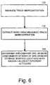
- FIG. 6 is a flowchart of operations implemented by a disk drive controller to detect altitude, according to some embodiments of the present invention.
- FIG. 7A is a graph that illustrates a windage torque component of non-repeatable runout for three different elevations at different locations of a disk storage surface.
- FIG. 7B is a graph that illustrates structural modes component of non-repeatable runout for three different elevations at different locations of a disk storage surface.
- phrases such as “between X and Y” and “between about X and Y” should be interpreted to include X and Y.
- phrases such as “between about X and Y” mean “between about X and about Y.”
- phrases such as “from about X to Y” mean “from about X to about Y.”
- spatially relative terms such as “under”, “below”, “lower”, “over”, “upper” and the like, may be used herein for ease of description to describe one element or feature's relationship to another element(s) or feature(s) as illustrated in the figures. It will be understood that the spatially relative terms are intended to encompass different orientations of the device in use or operation in addition to the orientation depicted in the figures. For example, if the device in the figures is inverted, elements described as “under” or “beneath” other elements or features would then be oriented “over” the other elements or features. Thus, the exemplary term “under” can encompass both an orientation of “over” and “under”.
- the device may be otherwise oriented (rotated 90 degrees or at other orientations) and the spatially relative descriptors used herein interpreted accordingly.
- the terms “upwardly”, “downwardly”, “vertical”, “horizontal” and the like are used herein for the purpose of explanation only unless specifically indicated otherwise.
- first”, “second”, etc. may be used herein to describe various elements, components, regions, layers and/or sections, these elements, components, regions, layers and/or sections should not be limited by these terms. These terms are only used to distinguish one element, component, region, layer or section from another element, component, region, layer or section. Thus, a “first” element, component, region, layer or section discussed below could also be termed a “second” element, component, region, layer or section without departing from the teachings of the present invention.
- the sequence of operations (or steps) is not limited to the order presented in the claims or figures unless specifically indicated otherwise.
- data storage disk and “disk” are intended to be interchangeable herein.
- transducer read/write transducer
- data transducer data transducer
- the present invention may be embodied in hardware (analog and/or discrete) and/or in software (including firmware, resident software, micro-code, etc.). Consequently, as used herein, the term “signal” may take the form of a continuous waveform and/or discrete value(s), such as digital value(s) in a memory or register.
- FIG. 1 A simplified diagrammatic representation of an exemplary disk drive that can incorporate embodiments of the present invention, generally designated as 10 , is illustrated in FIG. 1 .
- the disk drive 10 includes a disk stack 12 (illustrated as a single disk in FIG. 1 ) that is rotated by a spindle motor 14 .
- the spindle motor 14 is mounted to a base plate 16 .
- An actuator arm assembly 18 is also mounted to the base plate 16 .
- the disk drive 10 is configured to store and retrieve data responsive to write commands and read commands from a host device.
- a host device can include, but is not limited to, a desktop computer, a laptop computer, a personal digital assistant (PDA), a digital video recorder/player, a digital music recorder/player, and/or another electronic device that can be communicatively coupled to store and retrieve data in the disk drive 10 .
- PDA personal digital assistant
- the actuator arm assembly 18 includes a plurality of transducers 20 mounted to flexure arms 22 which are attached to actuator arms 24 that can rotate about a pivot bearing assembly 26 .
- Each transducer 20 may include, but is not limited to, a magnetoresistive (MR) element, a thin film inductive (TFI) element, and/or an inductive coil element.
- the actuator arm assembly 18 also includes a voice coil motor (VCM) 28 which moves the transducers 20 relative to the disk stack 12 .
- the spindle motor 14 and actuator arm assembly 18 are coupled to a controller and associated electronic circuits (collectively indicated as 30 ) mounted to a printed circuit board 32 .
- the controller 30 may include analog and/or digital circuitry, and typically includes a digital signal processor (DSP), a microprocessor-based controller and a random access memory (RAM) device.
- DSP digital signal processor
- RAM random access memory
- the disk stack 12 typically includes a plurality of disks 34 , each of which may have a pair of disk surfaces 36 , 36 .
- the disks 34 are mounted on a cylindrical shaft and are configured to rotate about axis 38 .
- the spindle motor 14 as mentioned above, rotates the disk stack 12 .
- the disks 34 are described as magnetic disks for purposes of illustration, alternatively, they may be optical disks or any other type of rewritable data storage disk.
- the plurality of transducers 20 are each adjacent to a different one of the disk surfaces 36 .
- Each transducer 20 is mounted to a corresponding flexure arm 22 which is attached to a corresponding portion of the actuator arm 24 that can rotate about the pivot bearing assembly 26 .
- the VCM 28 operates to move the actuator arm 24 and the transducers 20 relative to their respective disk surfaces 36 .
- FIG. 4 further illustrates one of the disks 34 of an exemplary disk drive, according to embodiments of the present invention.
- Data is stored on the disk 34 within a number of concentric tracks 40 (or cylinders).
- Each track is divided into a plurality of radially extending spokes (sectors) 42 on the disk 34 .
- Each spoke 42 is further divided into a servo spoke (sector) 44 and a data spoke (sector) 46 .
- the servo spokes 44 of the disk 34 are used to, among other things, accurately position a transducer 20 so that data can be properly written onto and read from the disk 34 .
- the servo spokes 44 can provide transducer location information such as a track identification field and data block address, for identifying the track and data block.
- the data spokes 46 are where non-servo related data (i.e., data from a host device) is stored and retrieved. Such data, upon proper conditions, may be overwritten.
- a host device can write data to and read data from the disk drive 10 by communicating respective write commands and read commands to the controller 30 that identify the associated block addresses of the disk 34 on which data is to be transferred.
- a controller 30 configured to detect disk drive altitude, according to some embodiments of the present invention, includes a data controller 70 , a servo controller 72 , a read/write channel 74 , and an instruction buffer 75 .
- the illustrated controller 30 includes two separate controllers 70 , 72 , instruction buffer 75 , and read/write channel 74 for purposes of illustration and discussion only. It is to be understood that the functionality that is described herein for one or more of those components may be consolidated in fewer components or distributed among more components.
- the controller 30 is configured to respond to read and write instructions from a host device 78 by reading and writing data on a head disk assembly (HDA) 77 .
- the HDA 77 can include the actuator arm assembly 18 , the disk stack 12 , and the spindle motor 14 ( FIGS. 1-3 ). More particularly, read instructions and write instructions with associated data and block addresses from the host device 78 can be buffered in the instruction buffer 75 .
- the data controller 70 can be configured to carry out a buffered write instruction by formatting the associated data into blocks with the appropriate header information, and to transfer the formatted data from the instruction buffer 75 , via the read/write channel 74 , to block addresses on the disk 34 that are identified by the write command.
- the data controller 70 can also be configured to carry out a buffered read instruction by reading, via the read write channel 74 , data from block addresses on the disk 34 that are identified by the read instruction and to transfer the data to the host device 78 .
- the servo controller 72 controls operation of the actuator arm 24 and generally performs two distinct functions: seek control and track following.
- the seek control function includes controllably moving the actuator arm 24 such that a transducer 20 is moved from an initial position to a target track position.
- the seek function is initiated when a host device 78 associated with the disk drive 10 issues a command to read data from or write data to a target track on a disk 34 .
- the track following function of the servo controller 72 is activated to center and maintain the transducer 20 on the target track until the desired data transfers are completed.
- the track following function of the servo controller 72 generally includes maintaining a transducer 20 at a desired position with respect to a track being followed (e.g., over a centerline of the track).
- a transducer 20 must be moved slightly during track following to maintain a desired position over a track. This is because, due to various factors, a track may appear to move beneath a transducer 20 .
- Runout generally refers to deviation from perfect circular motion and, more particularly, refers to variation in the distance between an external point of reference and a passing surface of a rotating object.
- “Repeatable runout” involves periodic deviations that occur with predictable regularity (hereafter “RRO”).
- “Nonrepeatable runout” involves random perturbations due to, for example, turbulent air flow inside the drive, bearing slop, shock events, and so on (hereafter “NRRO”).
- RRO is “repeatable” because it occurs in sync with a spinning disk.
- RRO may be caused by one or more of the following mechanical sources: a) spindle motor runout; b) disk slippage; c) disk warping; d) disturbances converted to RRO during a servo writing process due to, for example, NRRO, vibrations, resonances, media defects, or disk distortion due to clamping of the HDA.
- RRO may also be caused by electromagnetic imperfections due to low quality servo positioning bursts, even if they were mechanically recorded on the ideal circle. Such low quality servo positioning bursts can yield incorrect position information.
- Track misregistration can be mathematically deconvolved into RRO and NRRO components, as would be understood by one skilled in the art. Track misregistration is any relative off-track position between a transducer and a data track. Any relative motion, be it from actuator motion or runout, can create TMR. Embodiments of the present invention allow for altitude detection via TMR that results from purely disk runout or from purely actuator-related motions or from any combinations and constituents thereof.
- NRRO signatures at different frequencies provide a means for estimating, or at least bracketing, the altitude at which a disk drive is operating.
- the frequency or frequencies dependent “signatures” of NRRO are dependent upon construction, structures, assemblies, materials selection, operational characteristics, servo positioning algorithms, etc., of a given disk drive design.
- analysis of components of NRRO at different radial locations of a disk further enhance differences in the various NRRO signatures and thus allow a confident estimation of whether a particular disk drive is operating near sea level, near 5,000 feet above sea level, or at 10,000 feet and higher above sea level, for example.
- NRRO signatures be characterized on a case-by-case basis. A skilled practitioner can then decide which signature(s) to utilize individually or collectively to achieve a desired level of confidence in ascertaining the operating altitude or altitude range.
- a flowchart of operations carried out by a disk drive controller such as the controller 30 in FIG. 1 , to determine disk drive altitude, according to some embodiments of the present invention, is illustrated.
- the controller measures TMR (Block 100 ) and then extracts NRRO from the measured TMR (Block 110 ).
- One or more components of NRRO e.g., windage torque on an actuator, structural modes excited by airflow within a disk drive, etc.
- NRRO e.g., windage torque on an actuator, structural modes excited by airflow within a disk drive, etc.
- NRRO windage torque, structural modes, etc.
- spectral frequency and modal analysis
- statistical deconvolution algorithms well known to those skilled in this art.
- the practice of deconvolving the various elements of NRRO is a well understood technique to those skilled in this art.
- the storage surface of a disk is typically divided into an inner diameter (ID) region, a middle diameter (MD) region, and an outer diameter (OD) region.
- ID inner diameter
- MD middle diameter
- OD outer diameter
- components of NRRO are analyzed at one or more of the ID, MD, and OD regions.
- a controller may analyze windage torque at the OD region of a disk and structural modes at the MD region of the disk.
- embodiments of the present invention are not limited to just the ID, MD or OD radial regions of a disk. Any region of a disk may be utilized in accordance with embodiments of the present invention.
- windage torque is particularly affected by altitude in the OD region of a disk surface, and structural modes are particularly affected by altitude in the MD region.
- embodiments of the present invention are not limited to measurement and analysis of NRRO components at particular disk storage surface radial locations. Instead, NRRO components can be measured and analyzed at any disk storage surface radial location, without limitation. Moreover, any type or combination of NRRO components may be utilized.
- TMR and it's derivative NRRO
- TMR come from numerous sources related to sympathetic motion (resonance) of internal design features driven to cause TMR by air flow in the disk drive.
- numerous other discrete manifestations may occur.
- One such manifestation might be any one or more vibrational modes of the suspension 22 or the actuator arms 24 ( FIG. 3 ).
- one or more of the disks 36 ( FIG. 2 ) may be driven into resonance in one or more vibrational modes due to air flow.
- Another structure susceptible to multi-modal response is the flexible connector(s) that afford an electro-mechanical coupling between the actuator arm assembly 18 ( FIG. 3 ) and a printed circuit board 32 ( FIG. 1 ).
- a frequency band for example, may be a frequency range from one frequency F 1 to a higher frequency F 2 .
- a second frequency band could cover frequencies F 3 to F 4 , and so on. For a given drive design, these bands will constitute a “signature” of NRRO.
Landscapes
- Magnetic Record Carriers (AREA)
Abstract
Description
Claims (19)
Priority Applications (1)
| Application Number | Priority Date | Filing Date | Title |
|---|---|---|---|
| US11/256,299 US7245452B1 (en) | 2005-03-04 | 2005-10-21 | Disk drive with altitude detection via analysis of non-repeatable runout components |
Applications Claiming Priority (2)
| Application Number | Priority Date | Filing Date | Title |
|---|---|---|---|
| US65903205P | 2005-03-04 | 2005-03-04 | |
| US11/256,299 US7245452B1 (en) | 2005-03-04 | 2005-10-21 | Disk drive with altitude detection via analysis of non-repeatable runout components |
Publications (1)
| Publication Number | Publication Date |
|---|---|
| US7245452B1 true US7245452B1 (en) | 2007-07-17 |
Family
ID=38235603
Family Applications (1)
| Application Number | Title | Priority Date | Filing Date |
|---|---|---|---|
| US11/256,299 Expired - Fee Related US7245452B1 (en) | 2005-03-04 | 2005-10-21 | Disk drive with altitude detection via analysis of non-repeatable runout components |
Country Status (1)
| Country | Link |
|---|---|
| US (1) | US7245452B1 (en) |
Cited By (1)
| Publication number | Priority date | Publication date | Assignee | Title |
|---|---|---|---|---|
| US20090296262A1 (en) * | 2008-05-29 | 2009-12-03 | Fujitsu Limited | Flying height control method and circuit |
Citations (4)
| Publication number | Priority date | Publication date | Assignee | Title |
|---|---|---|---|---|
| US20030193727A1 (en) * | 2002-04-11 | 2003-10-16 | Seagate Technology Llc | Detecting head-disc interference using position error signal |
| US6771440B2 (en) * | 2001-12-18 | 2004-08-03 | International Business Machines Corporation | Adaptive event-based predictive failure analysis measurements in a hard disk drive |
| US20060044666A1 (en) * | 2004-08-27 | 2006-03-02 | Craig Fukushima | Method of performing self-servo write using a helium environment |
| US20060146443A1 (en) * | 2004-12-30 | 2006-07-06 | Joseph Chang | Method and apparatus for airflow transition edges on noise dampers in a hard disk drive |
-
2005
- 2005-10-21 US US11/256,299 patent/US7245452B1/en not_active Expired - Fee Related
Patent Citations (4)
| Publication number | Priority date | Publication date | Assignee | Title |
|---|---|---|---|---|
| US6771440B2 (en) * | 2001-12-18 | 2004-08-03 | International Business Machines Corporation | Adaptive event-based predictive failure analysis measurements in a hard disk drive |
| US20030193727A1 (en) * | 2002-04-11 | 2003-10-16 | Seagate Technology Llc | Detecting head-disc interference using position error signal |
| US20060044666A1 (en) * | 2004-08-27 | 2006-03-02 | Craig Fukushima | Method of performing self-servo write using a helium environment |
| US20060146443A1 (en) * | 2004-12-30 | 2006-07-06 | Joseph Chang | Method and apparatus for airflow transition edges on noise dampers in a hard disk drive |
Cited By (2)
| Publication number | Priority date | Publication date | Assignee | Title |
|---|---|---|---|---|
| US20090296262A1 (en) * | 2008-05-29 | 2009-12-03 | Fujitsu Limited | Flying height control method and circuit |
| US7692890B2 (en) | 2008-05-29 | 2010-04-06 | Toshiba Storage Device Corporation | Flying height control method and circuit |
Similar Documents
| Publication | Publication Date | Title |
|---|---|---|
| US7633698B2 (en) | Controlling a write inhibit threshold based on vibration | |
| JP4358700B2 (en) | Disk device and manufacturing method thereof | |
| US7499243B2 (en) | Disk drive with support structure for air dams and disk-vibration capacitive sensors | |
| US11776570B2 (en) | Reducing non-coherent repeatable runout in two-dimensional magnetic recording disk drives | |
| US7012777B1 (en) | Disk drive with capacitance sensing of disk vibration and feedforward control for removal of read/write head track misregistration | |
| US6963462B2 (en) | Servo detection control system, servo detection control method and hard disk drive | |
| US7567404B1 (en) | Method for measuring actuator velocity during self-servo-write | |
| US7450335B2 (en) | Reducing read/write head track misregistration | |
| US7391586B2 (en) | Servowriter ramp detection | |
| US7342736B1 (en) | Methods and disk drive that measure head flying height at power-on/off | |
| US7245452B1 (en) | Disk drive with altitude detection via analysis of non-repeatable runout components | |
| US6301797B1 (en) | Recognizing and compensating for disk shift in computer disk drives | |
| US20100238585A1 (en) | Method of controlling flying height of magnetic head of hard disk drive | |
| US7196513B2 (en) | Method for testing magnetic hard disk or magnetic head | |
| US7643239B2 (en) | Controller selection to reduce written-in run-out | |
| US6603630B1 (en) | Method and apparatus for monitoring track misregistration | |
| US7787209B1 (en) | Method and apparatus for compensating for repeatable runout using wide embedded runout correction fields | |
| US8089718B2 (en) | Method and apparatus for increasing storage capacity of a hard disk drive | |
| US7660071B1 (en) | Disk drive with altitude detection air vane | |
| JP2006209839A (en) | Servo track writer, magnetic disk device, and manufacturing method of magnetic disk device | |
| US7286318B1 (en) | Optimization of position mode seeking of a disk drive head based on measured open loop actuator response | |
| US6912098B2 (en) | Method for dynamically measuring suspension in-plane and out-plane thermal drift hard disk drives | |
| JP2004127495A (en) | Test method for hard magnetic disk or magnetic head | |
| US8068298B2 (en) | Harmonic selection for track following on a hard disk drive | |
| JP2007220204A (en) | Test method for disk drive device |
Legal Events
| Date | Code | Title | Description |
|---|---|---|---|
| AS | Assignment |
Owner name: MAXTOR CORPORATION, COLORADO Free format text: ASSIGNMENT OF ASSIGNORS INTEREST;ASSIGNORS:RIENER, TIMOTHY A.;SCHRECK, ERHARD;REEL/FRAME:017133/0829;SIGNING DATES FROM 20050928 TO 20051020 |
|
| STCF | Information on status: patent grant |
Free format text: PATENTED CASE |
|
| AS | Assignment |
Owner name: WELLS FARGO BANK, NATIONAL ASSOCIATION, AS COLLATERAL AGENT AND SECOND PRIORITY REPRESENTATIVE, CALIFORNIA Free format text: SECURITY AGREEMENT;ASSIGNORS:MAXTOR CORPORATION;SEAGATE TECHNOLOGY LLC;SEAGATE TECHNOLOGY INTERNATIONAL;REEL/FRAME:022757/0017 Effective date: 20090507 Owner name: JPMORGAN CHASE BANK, N.A., AS ADMINISTRATIVE AGENT AND FIRST PRIORITY REPRESENTATIVE, NEW YORK Free format text: SECURITY AGREEMENT;ASSIGNORS:MAXTOR CORPORATION;SEAGATE TECHNOLOGY LLC;SEAGATE TECHNOLOGY INTERNATIONAL;REEL/FRAME:022757/0017 Effective date: 20090507 Owner name: JPMORGAN CHASE BANK, N.A., AS ADMINISTRATIVE AGENT Free format text: SECURITY AGREEMENT;ASSIGNORS:MAXTOR CORPORATION;SEAGATE TECHNOLOGY LLC;SEAGATE TECHNOLOGY INTERNATIONAL;REEL/FRAME:022757/0017 Effective date: 20090507 Owner name: WELLS FARGO BANK, NATIONAL ASSOCIATION, AS COLLATE Free format text: SECURITY AGREEMENT;ASSIGNORS:MAXTOR CORPORATION;SEAGATE TECHNOLOGY LLC;SEAGATE TECHNOLOGY INTERNATIONAL;REEL/FRAME:022757/0017 Effective date: 20090507 |
|
| FPAY | Fee payment |
Year of fee payment: 4 |
|
| AS | Assignment |
Owner name: SEAGATE TECHNOLOGY INTERNATIONAL, CALIFORNIA Free format text: RELEASE;ASSIGNOR:JPMORGAN CHASE BANK, N.A., AS ADMINISTRATIVE AGENT;REEL/FRAME:025662/0001 Effective date: 20110114 Owner name: MAXTOR CORPORATION, CALIFORNIA Free format text: RELEASE;ASSIGNOR:JPMORGAN CHASE BANK, N.A., AS ADMINISTRATIVE AGENT;REEL/FRAME:025662/0001 Effective date: 20110114 Owner name: SEAGATE TECHNOLOGY HDD HOLDINGS, CALIFORNIA Free format text: RELEASE;ASSIGNOR:JPMORGAN CHASE BANK, N.A., AS ADMINISTRATIVE AGENT;REEL/FRAME:025662/0001 Effective date: 20110114 Owner name: SEAGATE TECHNOLOGY LLC, CALIFORNIA Free format text: RELEASE;ASSIGNOR:JPMORGAN CHASE BANK, N.A., AS ADMINISTRATIVE AGENT;REEL/FRAME:025662/0001 Effective date: 20110114 |
|
| AS | Assignment |
Owner name: THE BANK OF NOVA SCOTIA, AS ADMINISTRATIVE AGENT, CANADA Free format text: SECURITY AGREEMENT;ASSIGNOR:SEAGATE TECHNOLOGY LLC;REEL/FRAME:026010/0350 Effective date: 20110118 Owner name: THE BANK OF NOVA SCOTIA, AS ADMINISTRATIVE AGENT, Free format text: SECURITY AGREEMENT;ASSIGNOR:SEAGATE TECHNOLOGY LLC;REEL/FRAME:026010/0350 Effective date: 20110118 |
|
| AS | Assignment |
Owner name: SEAGATE TECHNOLOGY LLC, CALIFORNIA Free format text: TERMINATION AND RELEASE OF SECURITY INTEREST IN PATENT RIGHTS;ASSIGNOR:WELLS FARGO BANK, NATIONAL ASSOCIATION, AS COLLATERAL AGENT AND SECOND PRIORITY REPRESENTATIVE;REEL/FRAME:030833/0001 Effective date: 20130312 Owner name: SEAGATE TECHNOLOGY US HOLDINGS, INC., CALIFORNIA Free format text: TERMINATION AND RELEASE OF SECURITY INTEREST IN PATENT RIGHTS;ASSIGNOR:WELLS FARGO BANK, NATIONAL ASSOCIATION, AS COLLATERAL AGENT AND SECOND PRIORITY REPRESENTATIVE;REEL/FRAME:030833/0001 Effective date: 20130312 Owner name: SEAGATE TECHNOLOGY INTERNATIONAL, CAYMAN ISLANDS Free format text: TERMINATION AND RELEASE OF SECURITY INTEREST IN PATENT RIGHTS;ASSIGNOR:WELLS FARGO BANK, NATIONAL ASSOCIATION, AS COLLATERAL AGENT AND SECOND PRIORITY REPRESENTATIVE;REEL/FRAME:030833/0001 Effective date: 20130312 Owner name: EVAULT INC. (F/K/A I365 INC.), CALIFORNIA Free format text: TERMINATION AND RELEASE OF SECURITY INTEREST IN PATENT RIGHTS;ASSIGNOR:WELLS FARGO BANK, NATIONAL ASSOCIATION, AS COLLATERAL AGENT AND SECOND PRIORITY REPRESENTATIVE;REEL/FRAME:030833/0001 Effective date: 20130312 |
|
| FPAY | Fee payment |
Year of fee payment: 8 |
|
| FEPP | Fee payment procedure |
Free format text: MAINTENANCE FEE REMINDER MAILED (ORIGINAL EVENT CODE: REM.); ENTITY STATUS OF PATENT OWNER: LARGE ENTITY |
|
| LAPS | Lapse for failure to pay maintenance fees |
Free format text: PATENT EXPIRED FOR FAILURE TO PAY MAINTENANCE FEES (ORIGINAL EVENT CODE: EXP.); ENTITY STATUS OF PATENT OWNER: LARGE ENTITY |
|
| STCH | Information on status: patent discontinuation |
Free format text: PATENT EXPIRED DUE TO NONPAYMENT OF MAINTENANCE FEES UNDER 37 CFR 1.362 |
|
| FP | Lapsed due to failure to pay maintenance fee |
Effective date: 20190717 |
|
| AS | Assignment |
Owner name: SEAGATE TECHNOLOGY PUBLIC LIMITED COMPANY, CALIFORNIA Free format text: RELEASE BY SECURED PARTY;ASSIGNOR:THE BANK OF NOVA SCOTIA;REEL/FRAME:072193/0001 Effective date: 20250303 Owner name: SEAGATE TECHNOLOGY, CALIFORNIA Free format text: RELEASE BY SECURED PARTY;ASSIGNOR:THE BANK OF NOVA SCOTIA;REEL/FRAME:072193/0001 Effective date: 20250303 Owner name: SEAGATE TECHNOLOGY HDD HOLDINGS, CALIFORNIA Free format text: RELEASE BY SECURED PARTY;ASSIGNOR:THE BANK OF NOVA SCOTIA;REEL/FRAME:072193/0001 Effective date: 20250303 Owner name: I365 INC., CALIFORNIA Free format text: RELEASE BY SECURED PARTY;ASSIGNOR:THE BANK OF NOVA SCOTIA;REEL/FRAME:072193/0001 Effective date: 20250303 Owner name: SEAGATE TECHNOLOGY LLC, CALIFORNIA Free format text: RELEASE BY SECURED PARTY;ASSIGNOR:THE BANK OF NOVA SCOTIA;REEL/FRAME:072193/0001 Effective date: 20250303 Owner name: SEAGATE TECHNOLOGY INTERNATIONAL, CAYMAN ISLANDS Free format text: RELEASE BY SECURED PARTY;ASSIGNOR:THE BANK OF NOVA SCOTIA;REEL/FRAME:072193/0001 Effective date: 20250303 Owner name: SEAGATE HDD CAYMAN, CAYMAN ISLANDS Free format text: RELEASE BY SECURED PARTY;ASSIGNOR:THE BANK OF NOVA SCOTIA;REEL/FRAME:072193/0001 Effective date: 20250303 Owner name: SEAGATE TECHNOLOGY (US) HOLDINGS, INC., CALIFORNIA Free format text: RELEASE BY SECURED PARTY;ASSIGNOR:THE BANK OF NOVA SCOTIA;REEL/FRAME:072193/0001 Effective date: 20250303 Owner name: SEAGATE TECHNOLOGY PUBLIC LIMITED COMPANY, CALIFORNIA Free format text: RELEASE OF SECURITY INTEREST;ASSIGNOR:THE BANK OF NOVA SCOTIA;REEL/FRAME:072193/0001 Effective date: 20250303 Owner name: SEAGATE TECHNOLOGY, CALIFORNIA Free format text: RELEASE OF SECURITY INTEREST;ASSIGNOR:THE BANK OF NOVA SCOTIA;REEL/FRAME:072193/0001 Effective date: 20250303 Owner name: SEAGATE TECHNOLOGY HDD HOLDINGS, CALIFORNIA Free format text: RELEASE OF SECURITY INTEREST;ASSIGNOR:THE BANK OF NOVA SCOTIA;REEL/FRAME:072193/0001 Effective date: 20250303 Owner name: I365 INC., CALIFORNIA Free format text: RELEASE OF SECURITY INTEREST;ASSIGNOR:THE BANK OF NOVA SCOTIA;REEL/FRAME:072193/0001 Effective date: 20250303 Owner name: SEAGATE TECHNOLOGY LLC, CALIFORNIA Free format text: RELEASE OF SECURITY INTEREST;ASSIGNOR:THE BANK OF NOVA SCOTIA;REEL/FRAME:072193/0001 Effective date: 20250303 Owner name: SEAGATE TECHNOLOGY INTERNATIONAL, CAYMAN ISLANDS Free format text: RELEASE OF SECURITY INTEREST;ASSIGNOR:THE BANK OF NOVA SCOTIA;REEL/FRAME:072193/0001 Effective date: 20250303 Owner name: SEAGATE HDD CAYMAN, CAYMAN ISLANDS Free format text: RELEASE OF SECURITY INTEREST;ASSIGNOR:THE BANK OF NOVA SCOTIA;REEL/FRAME:072193/0001 Effective date: 20250303 Owner name: SEAGATE TECHNOLOGY (US) HOLDINGS, INC., CALIFORNIA Free format text: RELEASE OF SECURITY INTEREST;ASSIGNOR:THE BANK OF NOVA SCOTIA;REEL/FRAME:072193/0001 Effective date: 20250303 |