US7242763B2 - Systems and methods for far-end noise reduction and near-end noise compensation in a mixed time-frequency domain compander to improve signal quality in communications systems - Google Patents
Systems and methods for far-end noise reduction and near-end noise compensation in a mixed time-frequency domain compander to improve signal quality in communications systems Download PDFInfo
- Publication number
- US7242763B2 US7242763B2 US10/303,797 US30379702A US7242763B2 US 7242763 B2 US7242763 B2 US 7242763B2 US 30379702 A US30379702 A US 30379702A US 7242763 B2 US7242763 B2 US 7242763B2
- Authority
- US
- United States
- Prior art keywords
- gain
- gain value
- compander
- noise
- far
- Prior art date
- Legal status (The legal status is an assumption and is not a legal conclusion. Google has not performed a legal analysis and makes no representation as to the accuracy of the status listed.)
- Expired - Fee Related, expires
Links
Images


Classifications
-
- H—ELECTRICITY
- H04—ELECTRIC COMMUNICATION TECHNIQUE
- H04B—TRANSMISSION
- H04B1/00—Details of transmission systems, not covered by a single one of groups H04B3/00 - H04B13/00; Details of transmission systems not characterised by the medium used for transmission
- H04B1/06—Receivers
- H04B1/10—Means associated with receiver for limiting or suppressing noise or interference
- H04B1/12—Neutralising, balancing, or compensation arrangements
- H04B1/123—Neutralising, balancing, or compensation arrangements using adaptive balancing or compensation means
Definitions
- the present invention is directed to communications systems, and more particularly to a communications system using far-end noise reduction and near-end noise compensation to improve the clarity of the communications link.
- an elementary realization of a near-end noise compensator consists of a noise-adaptive gain controller for the far-end signal, whereby the gain applied is proportionate to the near-end noise level.
- noise compensation leads to far-end noise modulation (i.e., far-end noise is modulated by near-end noise).
- far-end noise is modulated by near-end noise
- all the level changes of the near-end noise are echoed in the far-end noise, which is an unwanted and annoying artifact.
- the near-end noise follows a pattern of loud-soft-loud
- the far-end noise follows the same pattern.
- Noise compensation should be designed such that near-end noise purposely and only modulates far-end speech, but no modulation should result for the far-end noise.
- amplitude modulation of a near-stationary signal such as steady background noise sounds unnatural and artificial while amplitude modulation of a non-stationary signal, such as speech, is acceptable to an extent.
- Human ears are by a magnitude more sensitive to amplitude modulation of near stationary noise than to amplitude modulation of speech.
- the present invention meets the needs described above in a noise-adaptive compander that amplifies the individual frequency components of the far-end signal by a gain value based on the noise estimates of a near-end signal and a far-end signal.
- the invention is directed toward a noise-adaptive compander adapted to amplify a far-end signal based on a near-end noise level estimate of a near-end signal and constrained by a far-end noise level estimate.
- the compander contains a first filter bank that separates the far-end signal into a number of frequency bands.
- the compander also contains a first noise estimator, which generates a noise estimate sequence from the near-end signal and a second noise estimator that generates a noise estimate sequence from the far-end signal.
- the compander further contains several gain units for computing the gain values for the far-end signal.
- the compander contains a noise-adaptive gain control (NGC) unit, which generates a gain value using the near-end noise estimate generated by a noise estimator.
- the NGC gain is used to calculate a “total” gain value for the full band signal.
- the transition points for the expander region, the linear region, the compressor region, and the limiter region are determined by the underlying compander rule applied, which can be either input-bounded, output-bounded, or mixed input-output bounded, as describe in the U.S.
- the total gain value is then used to create a compression gain curve according to the pre-selected rule (i.e., input, output, and input-output bounded compression).
- the total gain value is used to set the level of the linear gain region.
- the compression gain computation consists of two parts. First, a target gain value is computed, which is represented by the static compression curve. Second, a dynamic response is computed, which is determined by the attack and release time constants as described in the U.S. patent application Ser. No. 09/956,954 entitled “Noise Compensation Methods and Systems for Increasing the Clarity of Voice Communications” by Walter Etter, and herein incorporated by reference.
- the subband signal level determines the point on the compression curve and thereby sets the target gain value for the subband.
- the target compression gain is filtered by the attack and release control within the compressor gain computation unit.
- the far-end noise estimate and the pre-set maximum amount of noise reduction are used to set the expander gain curve.
- the subband signal level determines the point on the expansion curve and thereby set the target expansion gain value for the subband.
- the target expansion gain is subsequently filtered by the attack and release control within the expander gain computation unit.
- a master gain unit selects a master gain value for each subband.
- the master gain value is equal to the minimum out of the compression gain value, the expander gain value, and the total gain value. In the absence of an AGC gain unit, the total gain value equals the noise-adaptive gain value.
- the subband gain values are combined with the corresponding subband signals of the far-end signal in a combiner unit.
- the combiner unit is typically a multiplier unit which multiplies the master gain value with the appropriate subband signal of the far-end signal.
- the compander contains a synthesis filter bank, which receives the output of the combiner unit and recombines the subbands of the modified far-end signal into a full band signal.
- the present invention may also include an AGC gain unit which computes a level normalization gain value for the far-end signal.
- the level normalization gain value is computed for the full band signal rather than for each subband.
- the compander may also include a combiner unit for combining the noise-adaptive gain value and the level-normalization gain value into the total gain value. This newly computed total gain value is then used to create the compression gain curve in the compression gain unit.
- the compander may further include a scaling unit, which is used to apply a scaling factor to the master gain values for each subband in the far-end signal.
- the scaling factor reduces the individual master gain values to a value of less than or equal to one to avoid saturation.
- the compander may further include a gain smoothing unit that smoothes each subband master gain value by averaging each master gain value with the immediately neighboring values. That is, the master gain, G M , at frequency index k, is averaged with the master gain values having frequency indices k ⁇ 1 and k+1. Additionally, the compander may further include a limiter unit to reduce any peaks in the reconstructed full band signal and a reverse scaling unit to amplify the full band signal by multiplying the full band signal with the inverse of the scaling factor.
- the present invention also includes a method for amplifying the far-end signal based on near-end noise estimates.
- FIG. 1 is a block diagram illustrating an exemplary two-way noise-adaptive compander.
- FIG. 2 is an illustration of an exemplary input-output characteristic curve for the compander in accordance with the present invention.
- FIG. 3 is an illustration of a block diagram illustrating an exemplary mixed time-frequency domain compander.
- FIG. 4 is an illustration of coupling between a noise compensation gain and a noise reduction gain curve used in conjunction with the mixed time-frequency compander.
- FIG. 5 is an illustration of an exemplary mixed time-frequency compander gain curve that corresponds to the input-output characteristics curve shown in FIG. 2 .
- FIG. 6 is an illustration for the construction of an exemplary input-output compander characteristic curve.
- FIG. 7 is a logic flow diagram illustrating an exemplary routine for amplifying a far-end signal using noise estimates of both a far-end and a near-end signal.
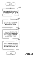
- FIG. 8 is a logic flow diagram illustrating an exemplary routine for computing a master gain value in accordance with the present invention.
- FIG. 9 is a logic flow diagram illustrating an exemplary routine for combining a scaled gain factor with the subband components of the far-end signal in the mixed time-frequency compander and reconstructing the modified far-end signal.
- the present invention is typically embodied in a mixed time-frequency domain compander, where the expander and compressor are implemented in the frequency domain (subband signals), while the limiter and the linear gain sections are implemented in the time-domain (full band signal).
- the gain of the linear gain section is calculated using subband signals, the gain is applied to the full band signal via a scaling procedure.
- the scaling procedure first scales back the compander gain in the frequency domain by the scaling factor and then performs the reciprocal reverse scaling on the time-domain (full band) signal. If the linear gain were applied in the frequency-domain, overflow (clipping) could not be prevented in the time-domain.
- clipping overflow
- a single frequency component may well be under the clipping level, the sum of all frequency components, which is essentially calculated in the inverse Fourier transform, may result in overflow in the time domain, depending on the phase relationship of the individual frequency components.
- the compander By realizing the expander part of the compander in the frequency domain, the compander is capable of reducing far-end noise in a wider dynamic range from low-level to high-level noise, whereas only low-level noise is reduced in a typical time-domain only expander. Furthermore, the compander operating on subband signals greatly reduces intermodulation between the individual subband signals, which occurs when far-end speech modulates far-end noise. For example, in a typical time-domain compander, a loud voiced vowel with strong frequency components at lower frequencies (e.g. /a/, /u/, /o/) may cause a short-term reduction of the compensation gain throughout the entire frequency spectrum leading to noticeable far-end noise modulations or fluctuations.
- Yet another advantage of the exemplary compander operating on subband signals is the ability to generate louder far-end speech. More so, if the compressor range is adapted to the near-end noise level. Higher speech levels in turn increase intelligibility in severely noisy environments.
- Yet another advantage of the exemplary compander is that cross-modulation (i.e., where the near-end noise modulates the far-end noise) is avoided.
- far-end noise is always at or below its original level and therefore is not affected by a time-variant noise compensation gain. This property is achieved by coupling far-end noise reduction with near-end noise compensation.
- FIG. 1 is a block diagram illustrating an exemplary two-way “compander” 100 .
- the term “compander” is derived from combing the terms “compressor” and “expander.”
- the two-way compander 100 consists of a far-end compander 105 dedicated to process the far-end signal 101 , a far-end noise estimator 110 , a near-end compander 115 dedicated to process the near-end signal 102 , and a near-end noise estimator 120 .
- Both the far-end compander 105 and the near-end compander 115 may operate both as a compressor and as an expander to regulate a signal, as the term implies.
- the far-end noise estimator 110 uses the far-end signal to derive a far-end noise estimate sequence, N X .
- the near-end noise estimator 120 uses the near-end signal to derive a near-end noise estimate sequence, N Y .
- Both noise estimate sequences, N X and N Y are then passed to the far-end compander 105 and near-end compander 115 , which use the noise estimates to calculate the appropriate gain level that need to be applied to the far-end signal 101 and the near-end signal 102 .
- the far-end compander 105 then applies the gain to the far-end signal 101 and passes it on to the near-end.
- the near-end compander 115 applies the gain to the near-end signal 102 and passes it to the far-end.
- Simple noise estimators use the signal level (time-domain noise estimator) or the signal spectrum (frequency domain noise estimator) during speech pauses to derive a noise estimate.
- Advanced noise estimators continuously adapt to noise, not only during speech pauses, but also during speech activity. Continuously adapting noise estimators are described in Etter, W., “Contributions to Noise Suppression in Monophonic Speech Signals,” Ph.D. thesis, Swiss Federal Institute of Technologies, ETH, Diss. No. 10210, Zurich, 1993 and in U.S. patent application Ser. No. 09/107,919 entitled “Estimating the Noise Component of a Signal” filed Jun. 30, 1998 by Walter Etter.
- the compander 100 of the present invention may be used in a device, such as a telephone handset, or in a subsystem of a communications network, such as a Mobile Switching Center (MSC), or any other communications network that is capable of handling voice communications.
- MSC Mobile Switching Center
- far-end and near-end are typically associated with the implementation in a device, such as a telephone for purposes of this application, the terms “far-end” and “near-end” are not subject to such a narrow interpretation and are used to describe the implementation of the compander in any communications system (either device or network).
- the terms “far-end” and “near-end” may be replaced by the terms “A-side” and “B-side.”
- FIG. 2 is an exemplary input-output curve for the compander 100 .
- the input-output curve 200 has five (5) separate regions, namely a linear attenuation region 205 , an expander region 210 , a linear amplification range 215 , a compressor amplification region 220 , and a limiter region 225 .
- the vertical axis of the gain curve 200 represents the level of a signal output from the compander used to drive an audio speaker amplifier or the like.
- the horizontal axis represents the signal level input in the compander from an input device, such as a microphone preamplifier.
- the compander 100 While operating in the expander region 210 of the gain curve 200 , the compander 100 amplifies the far-end signal by a value that depends on the far-end noise estimate, N X . As shown in FIG. 2 , the far-end noise signal, N X , shifts the expander region 210 either upward or downwards depending upon the noise level, N X .
- the expander utilized in the present invention is known as a “noise-adaptive” expander.
- the expander region 210 allows the compander 100 to amplify relatively low input signal level variations into relatively high output signal level variations.
- the compander 100 operates in the linear amplification region 215 along the gain curve 200 .
- the point on the curve where the transition between the expander region 210 and the linear amplification region 215 occurs is known as the linear onset point 230 .
- the compander 100 applies a linear amount of amplification to the input signal. In other words, the input signal is amplified in the entire linear region by an equal amount.
- the compander 100 ceases operating in the linear region 215 and begins to operate in the compression region 220 .
- the point on the curve where the transition between the linear amplification region 215 and the compressor region 220 occurs is known as the compressor onset point 235 .
- the compander 100 is then adapted to operate in a limiter region 225 . It should be noted that whenever the compander 100 is operating in the linear gain region, it is adapted to apply an amount of amplification determined by the near-end noise level, N Y . Whenever the compander is operating in either the compressor region 220 or the limiter region 225 , the amount of amplification determined by the near-end noise level is not fully applied, but gradually reduced for an increased input level.
- FIG. 3 is a block diagram illustrating an exemplary embodiment of a mixed time-frequency “compander” 300 .
- the compander 300 may be adapted to operate either as an expander (i.e., in the expander region) or as a compressor (i.e., in the compression region).
- the level of noise reduction applied by the compander to reduce the far-end noise within a communications system is determined by both far-end and near-end noise levels.
- compander 300 may be either a compander for the far-end signal or a compander for the near-end signal, as depicted in FIG. 1 . However, to simplify the explanation, the operation of the far-end compander 105 is described.
- FIG. 1 is a general block diagram of a two-way compander.
- FIG. 1 does not illustrate any specific realization of the far-end noise estimator 110 and the near-end noise estimator 120 or the far-end compander 105 and the near-end compander 115 .
- Each of these units may be realized in either the time domain or the frequency domain.
- the far-end estimator 110 , the near-end estimator 120 , the far-end compander 105 and the near-end compander 115 all conceptually include an analysis filter bank that splits the input signals into a number of frequency bands.
- each of the analysis filter banks that have the same input signal may be combined.
- the same analysis filter bank may be used for the far-end noise estimator 110 and the far-end noise adaptive compander 105 . Therefore, only one analysis filter bank 305 is used in FIG. 3 for the far-end signal.
- the far-end signal 101 is input into a filter bank 305 , which is typically a discrete Fourier Transform (DFT). However those skilled in the art will appreciate that other filters banks, such as wavelet or critical band filter banks, may be employed without departing from the scope of the invention.
- the filter bank 305 splits the far-end signal 101 into a number of subband signals, which are provided to the compander 105 . In FIG. 3 , the subband signals and subband gain values are represented by the thick lines, whereas the full band signal and the full band gain values are represented by the thin lines.
- the subband signals are input to a far-end noise estimator 310 , which is adapted to detect and estimate the noise levels within each frequency band associated with an input device at the far-end. Typically, the input device is a microphone. Those skilled in the art however, will appreciate that other input devices, such as an audio playback system, or the like may be used as an input device without departing from the scope of the invention.
- the far-end noise estimator 310 constantly generates a noise estimate, N X , for each subband of the far-end signal 101 .
- the noise estimate N X along with the subband signals are then input into an expander gain unit 315 , which calculates an expander gain value, G E , for each subband.
- the expander gain value, G E is determined using a single gain curve, more specifically a prototype expander gain curve, which is either stored in a look-up table or calculated using the expander gain unit 315 .
- the position of the gain curve is adjusted in the expander gain unit 315 for each subband to reflect the far-end noise level in each subband.
- the expander gain unit 315 uses the noise estimate, N X , to determine the appropriate gain curve for each subband and thereby set the linear onset point 230 on the gain curve 200 .
- the subband signals are also input to a compressor gain unit 320 , which calculates individual compressor gain values, G C , for each of the subbands.
- the compressor gain unit 320 uses a single compression gain curve, more specifically a prototype compression gain curve, to calculate the compression gain, G C , for each subband. The position of this gain curve is adjusted in the compressor gain unit 320 to reflect the total gain value, G TOT .
- the full band signal may also be input into an AGC gain unit 340 , which calculates a level-normalization gain value, G A .
- the near-end full band signal is input into a second filter bank 325 , which separates the full band signal into a number of subband signals.
- Each subband signal is then sent to the near-end noise estimator 330 , which generates the noise estimate sequence, N Y for each subband.
- the noise estimate sequences, N Y are then passed to a NGC gain unit 335 , which calculates a single noise-adaptive gain value G N .
- the noise-adaptive gain value, G N is then multiplied with the previously calculated level-normalizing gain value, G A , to create a total gain, G TOT , for the far-end compander 105 .
- the AGC unit 340 may be excluded from the compander 300 , in which case the total gain is equal to the noise-adaptive gain value.
- a frequency-domain noise estimator instead of a frequency-domain noise estimator, a considerably simpler time-domain noise estimator can be used, which does not require the analysis filter bank on the near-side.
- a time-domain estimator only provides one full band noise estimate, as opposed to a noise spectrum.
- a time-domain noise estimator is generally inferior to a frequency-domain noise estimator in terms of accuracy and adaptation speed.
- the total gain, G TOT is input to the compressor gain unit 320 , where it is used to vary a compressor onset point on the compressor gain curves (i.e., the point along the gain curves where the linear gain region ends and a compression region begins).
- the onset point for the compression region is varied by shifting the entire compression curve downwards or upwards.
- the expander gain values, G E , for each subband, the compressor gain values, G C , for each subband, and the total gain value, G TOT are then input into a master gain unit 345 .
- the master gain unit 345 selects a master gain value, G M , for each subband of the far-end signal 101 .
- the master gain value, G M is used to amplify or reduce each of the corresponding subband signals of the far-end signal 101 .
- the noise reduction gain is coupled to the noise compensation gain by limiting the expander gain to G TOT . In other words, noise reduction is coupled to noise compensation by keeping the amount of noise reduction equal to the amount of noise compensation or when the amount of noise reduction equals the amount of noise compensation plus a constant value.
- the expander gain curve when combined with the linear gain curve and the compressor gain curve to create the compander system curve (described below), insures that there is no time-variable gain in the far-end noise region.
- the far-end noise signal remains at its original level (or a fixed amount below its original level).
- the master gain values, G M , for each subband are then passed through a gain smoothing unit 350 .
- the gain smoothing unit 350 filters each subband master gain value, G M .
- This smoothing operation may be performed along the frequency axis, along the time axis, or along both the time and frequency axes.
- the master gain value, G M (k,i) for a frequency index k, and time index i may be calculated by determining a weighted average of only three neighboring values. That is, only the master gain values at frequency indices k ⁇ 1, k, and k+1 and the time indices i (current time index), i ⁇ 1 and i ⁇ 2 (passed time indices) are taken into account.
- smoothing the master gain values is a two-step process. First, smoothing along the frequency axis may be calculated from the equation:
- G _ M ⁇ ( k , i ) 1 4 ⁇ G M , ⁇ ( k - 1 , i ) + 1 2 ⁇ G M ⁇ ( k , i ) + 1 4 ⁇ G M , ⁇ ( k + 1 , i )
- smoothing along the time axis may be calculated using the equation:
- G ⁇ M ⁇ ( k , i ) 1 2 ⁇ G _ M , ⁇ ( k , i ) + 1 3 ⁇ G _ M ⁇ ( k , i - 1 ) + 1 6 ⁇ G _ M , ⁇ ( k , i - 2 )
- smoothing may be a single step process in which smoothing is applied only along a single axis.
- the smoothed master gain values may be calculated using the equation:
- G ⁇ M ⁇ ( k , i ) 1 4 ⁇ G M , ⁇ ( k - 1 , i ) + 1 2 ⁇ G M ⁇ ( k , i ) + 1 4 ⁇ G M , ⁇ ( k + 1 , i )
- the smoothed master gain values may be calculated using the equation:
- G ⁇ M ⁇ ( k , i ) 1 2 ⁇ G M , ⁇ ( k , i ) + 1 3 ⁇ G M ⁇ ( k , i - 1 ) + 1 6 ⁇ G M , ⁇ ( k , i - 2 )
- critical band weighting in which frequency bands within critical bands are averaged.
- the smoothed gain values ⁇ tilde over (G) ⁇ M (k,i) are then passed through a scaling unit 355 .
- the scaling unit 355 insures that the largest gain value is scaled to a value less than or equal to one.
- the maximum gain value, max ⁇ tilde over (G) ⁇ M (0,i), ⁇ tilde over (G) ⁇ M (1,i), . . . ⁇ tilde over (G) ⁇ M (N ⁇ 1,i) ⁇ is determined out of the N subbands at each time instance, i.
- ⁇ tilde over (G) ⁇ M (N ⁇ 1,i) ⁇ is determined from the subband master gain values.
- the maximum gain value is then used to scale all of the other gain values.
- a larger scaling factor may be used, such as the maximum gain value rounded up to the nearest power of 2. For example, if the maximum gain value is 7, max ⁇ tilde over (G) ⁇ M (0,i), ⁇ tilde over (G) ⁇ M (1,i), . . . ⁇ tilde over (G) ⁇ M (N ⁇ 1,i) ⁇ may be rounded up to 8 (2 3 ).
- the scaling unit 355 is implemented on a DSP, rounding up to the nearest power of 2 allows the use of simple and inexpensive shift operation, rather than requiring a complex division to perform the scaling.
- the scaled gain values may be calculated using the equation:
- G ⁇ M ⁇ ( k , i ) 1 c * G ⁇ M ⁇ ( k , i ) for 0 ⁇ k ⁇ N - 1
- the inverse Fourier transform will produce a time-domain signal without saturating. Note that maximum of the filter master gain values is smaller than the total gain.
- the scaled master gain values, ⁇ M (time and frequency indices not shown for simplicity) are then combined with the corresponding subband signals to modify the far-end signal.
- the modified subband signals are then passed through a synthesis filter bank 360 , which combines the subband signals into a full band signal.
- the synthesis filter is an inverse discrete Fourier transform unit.
- wavelet or critical band filter banks may be employed without departing from the scope of the invention.
- the limiter 365 reduces the “peaks” in the time-domain signal so that any subsequent reverse scaling, or amplification, does not result in saturation.
- the output of the limiter 365 is input to a reverse scaling unit 370 , which amplifies the time-domain signal up to the desired amplitude level by multiplying the output of the limiter by the scaling factor, c.
- the reverse scaling unit 370 provides the linear gain, reduced by the compressor gain, the expander gain, and the limiter gain. In other words, the linear gain and the limiter gain are applied to the full band signal, while the expander gain and the compressor gain are applied to the subband signals.
- FIG. 4 is an illustration of the coupling between the noise compensation gain curve 400 and the noise reduction gain curve 401 when noise reduction and noise compensation are implemented in two separate entities.
- the noise reduction to the noise compensation By coupling the noise reduction to the noise compensation, cross modulation of the far-end noise by the near-end noise is avoided.
- G TOT 420 Once the total gain, G TOT 420 , has been calculated (described above), the coupling of the compensation gain curve 400 to the noise reduction gain curve 401 is achieved by reducing the noise reduction gain curve 401 by an equal amount (or an equal amount plus a constant) in the region where far-end noise occurs. If the compensation gain 405 is combined with an equal but negative noise reduction gain 435 , these parts sum up to a value of zero gain in the far-end noise region.
- G NR may be added to the far-end noise region.
- the noise compensation and noise reduction are separate entities, these functions are carried out in sequence. That is, the far-end signal is first processed by the noise reduction and then by the noise compensation, or vice versa.
- line 440 is the horizontal coordinate (abscissa) of the noise reduction graph 401 . Since the total gain, G TOT 420 , is already applied in the noise compensation entity, zero gain is applied in the linear section 430 of the noise reduction entity.
- line 445 is the horizontal coordinate (abscissa) of the noise reduction graph 401 , which means that a gain of G TOT 420 is applied in the linear region 430 .
- the noise compensation gain 400 and the noise reduction gain 401 represent the two parts of the compander gain curve. In this case, the coupling is established directly by a compander gain curve, as illustrated in FIG. 5 .
- FIG. 5 is an illustration of an exemplary compander gain curve 500 for compander 100 with coupling between the noise compensation gain curve 400 and the noise reduction gain curve 401 in order to avoid cross modulation.
- the total gain in the far-end noise region 435 is constant and independent of the near-end noise, N Y . Consequently, the far-end noise will not be modulated by the near-end noise. Furthermore, if the total gain in the far-end noise region 435 is negative, as shown in FIG. 5A , the far-end noise is reduced by an equal amount.
- FIG. 6 is an illustration for the build-up construction of the compander input-output characteristic that corresponds to the gain curve 500 .
- the expander gain 425 and the compressor gain 410 are applied to the subband signals.
- the linear gain 405 is applied to the full band signal via a scaling procedure but the range of the linear gain section 405 is set separately for each subband.
- the limiter gain 415 is also applied to the full band signal.
- FIG. 6 shows the combined effect of these four compander sections for a single subband.
- FIG. 7 is a logic flow diagram illustrating an exemplary routine 700 for reducing the far-end noise and compensating for near-end noise in a communications system.
- the routine 700 begins at 705 in which the far-end signal is separated into individual subbands.
- all of the subbands are passed to a far-end noise estimator unit 310 for the far-end signal, where a noise estimate sequence, N X , is generated for each subband.
- the near-end signal is passed through a filter bank 225 and separated into individual subbands.
- the subbands of the near-end signal are input to the near-end noise estimator 330 , which generates a near-end noise estimate, N Y , for each subband.
- a full band noise-adaptive gain value is computed using the noise estimates, N Y , of the subbands.
- a level normalization gain value is computed at 730 using the full band far-end signal.
- the level normalization gain value and the noise-adaptive gain value are combined to create a total gain value, G TOT .
- the total gain value, G TOT is passed to a compressor gain unit 320 along with the far-end subband signals.
- the total gain value, G TOT is used by the compressor gain unit 320 to vary the compressor onset point on the compressor gain curves.
- the onset point for the compression region can be controlled in three different ways: input-bounded, output-bounded, or mixed input-output bounded.
- an expander gain value, G E is computed using the far-end noise estimate, N X , for each subband.
- a master gain unit 345 computes a master gain value, G M , for each subband of the far-end signal.
- the master gain value of each subband is combined with the corresponding far-end subband signal.
- FIG. 8 is a logic flow diagram illustrating routing 800 from step 750 ( FIG. 7 ) of an exemplary method for computing the scaled master gain value, ⁇ tilde over (G) ⁇ M , for each subband.
- the master gain value, G M for each subband is selected by taking the minimum value among the expander gain, G E , the compressor gain value, G C , the total gain value, G TOT , and a user-configurable maximum gain value, G MAX .
- each master gain value, G M is smoothed by applying a smoothing filter. This filtering operation can be performed along the frequency axis, along the time axis, or both the frequency and time axis.
- each master gain value is smoothed by using a second order finite-impulse response (FIR) filter with three coefficients, in which case only three neighboring values are used.
- FIR finite-impulse response
- G _ M ⁇ ( k , i ) 1 4 ⁇ G M , ⁇ ( k - 1 , i ) + 1 2 ⁇ G M ⁇ ( k , i ) + 1 4 ⁇ G M , ⁇ ( k + 1 , i )
- G M (k,i) is the master gain value for the k th subband at time instance i.
- the master gain ⁇ tilde over (G) ⁇ M (k,i) smoothed across time may be represented by the equation
- G ⁇ M ⁇ ( k , i ) 1 2 ⁇ G _ M , ⁇ ( k , i ) + 1 3 ⁇ G _ M ⁇ ( k , i - 1 ) + 1 6 ⁇ G _ M , ⁇ ( k , i - 2 )
- a scaling factor, c is calculated and applied to each of the smoothed subband master gain values.
- each smoothed master gain value is divided by the scaling factor, c, to produce a scaled master gain value equal to or less than one for each subband.
- the scaled gain values may be calculated using the equation:
- G ⁇ M ⁇ ( k , i ) 1 c * G ⁇ M ⁇ ( k , i ) for 0 ⁇ k ⁇ N - 1
- a larger scaling factor may be used, such as the maximum gain value rounded up to the nearest power of 2 (2, 4, 8, 16, 32, etc.).
- FIG. 9 is a logic flow diagram illustrating routine 900 from step 755 of FIG. 7 illustrating an exemplary routine for combining the scaled subband gain values with the far-end subband signals.
- Routine 900 begins at 905 , in which the subbands are combined into a full band signal.
- a synthesis filter bank 360 is typically used to recombine the individual subband signals into a single full band signal.
- the full band signal is then input to a limiter 365 along with the scaling factor, c.
- the limiter 365 reduces the “peaks” in the full band signal to eliminate any potential saturation when the full band signal is amplified.
- the full band signal is input to a reverse scaling unit 370 , which amplifies the full band signal by multiplying it by the scaling factor, c. The scaled full band signal is then provided to the near-end.
Landscapes
- Engineering & Computer Science (AREA)
- Computer Networks & Wireless Communication (AREA)
- Signal Processing (AREA)
- Soundproofing, Sound Blocking, And Sound Damping (AREA)
Abstract
Description
G TOT =G A * G N
Alternatively, the
G M=min{G E ,G C ,G TOT ,G MAX}
where GMAX is a pre-set maximum value that may be configured by the user and is used to set the maximum gain of the compander. For example, GMAX may be set to 20 dB. In the
Next, smoothing along the time axis may be calculated using the equation:
Alternatively, smoothing may be a single step process in which smoothing is applied only along a single axis. For the special case, when smoothing is applied along only the frequency axis, the smoothed master gain values may be calculated using the equation:
For the special case, when smoothing is applied only along the time-axis, the smoothed master gain values may be calculated using the equation:
Those skilled in the art will appreciate that other weighting schemes may be applied. For example, smoothing across frequency bands may be performed by critical band weighting, in which frequency bands within critical bands are averaged. For a review of critical bands, see Zwicker, E. and Fastl, H., “Psychoacoustics,” published by Springer 1990.
where c may be determined by the equation c=max{{tilde over (G)}M (0,i), {tilde over (G)}M (1,i) . . . {tilde over (G)}M (N−1,i)} as indicated above. By scaling the gain values in this way, the inverse Fourier transform will produce a time-domain signal without saturating. Note that maximum of the filter master gain values is smaller than the total gain. That is, max{{tilde over (G)}M (0,i), {tilde over (G)}M (1,i), . . . {tilde over (G)}M (N−1,i)}≦GTOT. Therefore, to further reduce the complexity of the algorithm, one can also derive the scaling factor from the total gain GTOT by using c≈GTOT
G M=min{G E ,G C ,G TOT ,G MAX}
At 810, each master gain value, GM, is smoothed by applying a smoothing filter. This filtering operation can be performed along the frequency axis, along the time axis, or both the frequency and time axis. In the exemplary embodiment, each master gain value is smoothed by using a second order finite-impulse response (FIR) filter with three coefficients, in which case only three neighboring values are used. Thus, the master gain values smoothed across frequency may be represented by the equations:
where GM(k,i) is the master gain value for the kth subband at time instance i. Likewise, the master gain {tilde over (G)}M (k,i), smoothed across time may be represented by the equation
For implementation efficiency, a larger scaling factor may be used, such as the maximum gain value rounded up to the nearest power of 2 (2, 4, 8, 16, 32, etc.).
Claims (29)
Priority Applications (1)
| Application Number | Priority Date | Filing Date | Title |
|---|---|---|---|
| US10/303,797 US7242763B2 (en) | 2002-11-26 | 2002-11-26 | Systems and methods for far-end noise reduction and near-end noise compensation in a mixed time-frequency domain compander to improve signal quality in communications systems |
Applications Claiming Priority (1)
| Application Number | Priority Date | Filing Date | Title |
|---|---|---|---|
| US10/303,797 US7242763B2 (en) | 2002-11-26 | 2002-11-26 | Systems and methods for far-end noise reduction and near-end noise compensation in a mixed time-frequency domain compander to improve signal quality in communications systems |
Publications (2)
| Publication Number | Publication Date |
|---|---|
| US20040101038A1 US20040101038A1 (en) | 2004-05-27 |
| US7242763B2 true US7242763B2 (en) | 2007-07-10 |
Family
ID=32325074
Family Applications (1)
| Application Number | Title | Priority Date | Filing Date |
|---|---|---|---|
| US10/303,797 Expired - Fee Related US7242763B2 (en) | 2002-11-26 | 2002-11-26 | Systems and methods for far-end noise reduction and near-end noise compensation in a mixed time-frequency domain compander to improve signal quality in communications systems |
Country Status (1)
| Country | Link |
|---|---|
| US (1) | US7242763B2 (en) |
Cited By (13)
| Publication number | Priority date | Publication date | Assignee | Title |
|---|---|---|---|---|
| US20050163372A1 (en) * | 2004-01-28 | 2005-07-28 | Shingo Kida | Video signal processor and method of processing video signal |
| US20060271356A1 (en) * | 2005-04-01 | 2006-11-30 | Vos Koen B | Systems, methods, and apparatus for quantization of spectral envelope representation |
| US20090147938A1 (en) * | 2007-12-10 | 2009-06-11 | Microsoft Corporation | Removing near-end frequencies from far-end sound |
| US20090147942A1 (en) * | 2007-12-10 | 2009-06-11 | Microsoft Corporation | Reducing Echo |
| US20090150149A1 (en) * | 2007-12-10 | 2009-06-11 | Microsoft Corporation | Identifying far-end sound |
| US20090299742A1 (en) * | 2008-05-29 | 2009-12-03 | Qualcomm Incorporated | Systems, methods, apparatus, and computer program products for spectral contrast enhancement |
| US20100296668A1 (en) * | 2009-04-23 | 2010-11-25 | Qualcomm Incorporated | Systems, methods, apparatus, and computer-readable media for automatic control of active noise cancellation |
| US20120095755A1 (en) * | 2009-06-19 | 2012-04-19 | Fujitsu Limited | Audio signal processing system and audio signal processing method |
| US20120259625A1 (en) * | 2009-09-14 | 2012-10-11 | Srs Labs, Inc. | System for processing an audio signal to enhance speech intelligibility |
| US8538749B2 (en) | 2008-07-18 | 2013-09-17 | Qualcomm Incorporated | Systems, methods, apparatus, and computer program products for enhanced intelligibility |
| US8639294B2 (en) | 2012-05-01 | 2014-01-28 | Audyssey Laboratories, Inc. | System and method for performing automatic gain control in mobile phone environments |
| US9053697B2 (en) | 2010-06-01 | 2015-06-09 | Qualcomm Incorporated | Systems, methods, devices, apparatus, and computer program products for audio equalization |
| US10951859B2 (en) | 2018-05-30 | 2021-03-16 | Microsoft Technology Licensing, Llc | Videoconferencing device and method |
Families Citing this family (15)
| Publication number | Priority date | Publication date | Assignee | Title |
|---|---|---|---|---|
| US7260209B2 (en) * | 2003-03-27 | 2007-08-21 | Tellabs Operations, Inc. | Methods and apparatus for improving voice quality in an environment with noise |
| PT1875463T (en) | 2005-04-22 | 2019-01-24 | Qualcomm Inc | Systems, methods, and apparatus for gain factor smoothing |
| US9454974B2 (en) * | 2006-07-31 | 2016-09-27 | Qualcomm Incorporated | Systems, methods, and apparatus for gain factor limiting |
| US8275611B2 (en) * | 2007-01-18 | 2012-09-25 | Stmicroelectronics Asia Pacific Pte., Ltd. | Adaptive noise suppression for digital speech signals |
| US8868418B2 (en) * | 2007-06-15 | 2014-10-21 | Alon Konchitsky | Receiver intelligibility enhancement system |
| US20080312916A1 (en) * | 2007-06-15 | 2008-12-18 | Mr. Alon Konchitsky | Receiver Intelligibility Enhancement System |
| US8868417B2 (en) * | 2007-06-15 | 2014-10-21 | Alon Konchitsky | Handset intelligibility enhancement system using adaptive filters and signal buffers |
| US20100057475A1 (en) * | 2008-08-26 | 2010-03-04 | Nelson Sollenberger | Method and system for digital gain control in an audio codec |
| EP2234105B1 (en) * | 2009-03-23 | 2011-06-08 | Harman Becker Automotive Systems GmbH | Background noise estimation |
| US20120257761A1 (en) * | 2011-04-11 | 2012-10-11 | Samsung Electronics Co. Ltd. | Apparatus and method for auto adjustment of volume in a portable terminal |
| CN103325380B (en) | 2012-03-23 | 2017-09-12 | 杜比实验室特许公司 | Gain for signal enhancing is post-processed |
| EP2898506B1 (en) * | 2012-09-21 | 2018-01-17 | Dolby Laboratories Licensing Corporation | Layered approach to spatial audio coding |
| US9647624B2 (en) * | 2014-12-31 | 2017-05-09 | Stmicroelectronics Asia Pacific Pte Ltd. | Adaptive loudness levelling method for digital audio signals in frequency domain |
| KR101715198B1 (en) * | 2015-11-18 | 2017-03-10 | 광주과학기술원 | Speech Reinforcement Method Using Selective Power Budget |
| US10410654B2 (en) * | 2017-10-27 | 2019-09-10 | Bestechnic (Shanghai) Co., Ltd. | Active noise control headphones |
Citations (10)
| Publication number | Priority date | Publication date | Assignee | Title |
|---|---|---|---|---|
| US4628526A (en) | 1983-09-22 | 1986-12-09 | Blaupunkt-Werke Gmbh | Method and system for matching the sound output of a loudspeaker to the ambient noise level |
| US4829565A (en) | 1987-10-20 | 1989-05-09 | Goldberg Robert M | Telephone with background volume control |
| US5107539A (en) | 1989-09-01 | 1992-04-21 | Pioneer Electronic Corporation | Automatic sound volume controller |
| US5509081A (en) | 1992-10-21 | 1996-04-16 | Nokia Technology Gmbh | Sound reproduction system |
| US5524148A (en) | 1993-12-29 | 1996-06-04 | At&T Corp. | Background noise compensation in a telephone network |
| US5553134A (en) | 1993-12-29 | 1996-09-03 | Lucent Technologies Inc. | Background noise compensation in a telephone set |
| WO1997010586A1 (en) | 1995-09-14 | 1997-03-20 | Ericsson Inc. | System for adaptively filtering audio signals to enhance speech intelligibility in noisy environmental conditions |
| US20030091182A1 (en) * | 1999-11-03 | 2003-05-15 | Tellabs Operations, Inc. | Consolidated voice activity detection and noise estimation |
| US7010118B2 (en) * | 2001-09-21 | 2006-03-07 | Agere Systems, Inc. | Noise compensation methods and systems for increasing the clarity of voice communications |
| US7058368B2 (en) * | 2002-06-27 | 2006-06-06 | Nortel Networks Limited | Adaptive feedforward noise cancellation circuit |
-
2002
- 2002-11-26 US US10/303,797 patent/US7242763B2/en not_active Expired - Fee Related
Patent Citations (10)
| Publication number | Priority date | Publication date | Assignee | Title |
|---|---|---|---|---|
| US4628526A (en) | 1983-09-22 | 1986-12-09 | Blaupunkt-Werke Gmbh | Method and system for matching the sound output of a loudspeaker to the ambient noise level |
| US4829565A (en) | 1987-10-20 | 1989-05-09 | Goldberg Robert M | Telephone with background volume control |
| US5107539A (en) | 1989-09-01 | 1992-04-21 | Pioneer Electronic Corporation | Automatic sound volume controller |
| US5509081A (en) | 1992-10-21 | 1996-04-16 | Nokia Technology Gmbh | Sound reproduction system |
| US5524148A (en) | 1993-12-29 | 1996-06-04 | At&T Corp. | Background noise compensation in a telephone network |
| US5553134A (en) | 1993-12-29 | 1996-09-03 | Lucent Technologies Inc. | Background noise compensation in a telephone set |
| WO1997010586A1 (en) | 1995-09-14 | 1997-03-20 | Ericsson Inc. | System for adaptively filtering audio signals to enhance speech intelligibility in noisy environmental conditions |
| US20030091182A1 (en) * | 1999-11-03 | 2003-05-15 | Tellabs Operations, Inc. | Consolidated voice activity detection and noise estimation |
| US7010118B2 (en) * | 2001-09-21 | 2006-03-07 | Agere Systems, Inc. | Noise compensation methods and systems for increasing the clarity of voice communications |
| US7058368B2 (en) * | 2002-06-27 | 2006-06-06 | Nortel Networks Limited | Adaptive feedforward noise cancellation circuit |
Non-Patent Citations (7)
| Title |
|---|
| E.A. Kretsinger, N.B. Young, "The use of fast limiting to improve the intelligibility of speech in noise," Speech Monogr., vol. 27, 1960, pp. 63-69. |
| E.F. Stikvoort, "Digital dynamic range compressor for audio," J. Audio Eng. Soc., vol. 34, No. 1/2, Jan./Feb. 1986, pp. 3-9. |
| I.B. Thomas, R.J. Niederjohn, "Enhancement of speech intelligibility at high noise levels by filtering and clipping," J. of the Acoust. Soc. Of Am., vol. 16, 1968, pp. 412-415. |
| R.J. Niederjohn, J.H. Grotelueschen, "The Enhancement of Speech Intelligibility in High Noise Levels by High-Pass Filtering Followed by Rapid Amplitude Compression," IEEE Trans. On Acoustics, Speech and Signal Proc., vol. ASSP-24, No. 4, Aug. 1976, pp. 277-282. |
| W. Etter, "Contribution to Noise Suppression in Monophonic Speech Signals," PhD. Thesis, Swiss Federal Institute of Technologies, ETH, Diss. No. 10210, Zurich, 1993. |
| W.Etter, G.S. Moschytz, "Noise Reduction by Noise-Adaptive Spectral Magnitude Expansion." J. Audio Eng. Soc., vol. 42, No. 5, May 1994, pp. 341-349. |
| Zwicker, E., Fastl, H., "Psychoacoustics," Springer 1990. |
Cited By (35)
| Publication number | Priority date | Publication date | Assignee | Title |
|---|---|---|---|---|
| US7394932B2 (en) * | 2004-01-28 | 2008-07-01 | Victor Company Of Japan, Ltd. | Video signal processor and method of processing video signal |
| US20050163372A1 (en) * | 2004-01-28 | 2005-07-28 | Shingo Kida | Video signal processor and method of processing video signal |
| US8140324B2 (en) | 2005-04-01 | 2012-03-20 | Qualcomm Incorporated | Systems, methods, and apparatus for gain coding |
| US20060277042A1 (en) * | 2005-04-01 | 2006-12-07 | Vos Koen B | Systems, methods, and apparatus for anti-sparseness filtering |
| US20060282263A1 (en) * | 2005-04-01 | 2006-12-14 | Vos Koen B | Systems, methods, and apparatus for highband time warping |
| US20070088542A1 (en) * | 2005-04-01 | 2007-04-19 | Vos Koen B | Systems, methods, and apparatus for wideband speech coding |
| US20070088541A1 (en) * | 2005-04-01 | 2007-04-19 | Vos Koen B | Systems, methods, and apparatus for highband burst suppression |
| US20080126086A1 (en) * | 2005-04-01 | 2008-05-29 | Qualcomm Incorporated | Systems, methods, and apparatus for gain coding |
| US20060277038A1 (en) * | 2005-04-01 | 2006-12-07 | Qualcomm Incorporated | Systems, methods, and apparatus for highband excitation generation |
| US8484036B2 (en) | 2005-04-01 | 2013-07-09 | Qualcomm Incorporated | Systems, methods, and apparatus for wideband speech coding |
| US8364494B2 (en) | 2005-04-01 | 2013-01-29 | Qualcomm Incorporated | Systems, methods, and apparatus for split-band filtering and encoding of a wideband signal |
| US8260611B2 (en) | 2005-04-01 | 2012-09-04 | Qualcomm Incorporated | Systems, methods, and apparatus for highband excitation generation |
| US8332228B2 (en) | 2005-04-01 | 2012-12-11 | Qualcomm Incorporated | Systems, methods, and apparatus for anti-sparseness filtering |
| US8244526B2 (en) | 2005-04-01 | 2012-08-14 | Qualcomm Incorporated | Systems, methods, and apparatus for highband burst suppression |
| US8069040B2 (en) | 2005-04-01 | 2011-11-29 | Qualcomm Incorporated | Systems, methods, and apparatus for quantization of spectral envelope representation |
| US8078474B2 (en) | 2005-04-01 | 2011-12-13 | Qualcomm Incorporated | Systems, methods, and apparatus for highband time warping |
| US20060271356A1 (en) * | 2005-04-01 | 2006-11-30 | Vos Koen B | Systems, methods, and apparatus for quantization of spectral envelope representation |
| US20090150149A1 (en) * | 2007-12-10 | 2009-06-11 | Microsoft Corporation | Identifying far-end sound |
| US8744069B2 (en) | 2007-12-10 | 2014-06-03 | Microsoft Corporation | Removing near-end frequencies from far-end sound |
| US20090147938A1 (en) * | 2007-12-10 | 2009-06-11 | Microsoft Corporation | Removing near-end frequencies from far-end sound |
| US8219387B2 (en) | 2007-12-10 | 2012-07-10 | Microsoft Corporation | Identifying far-end sound |
| US8433061B2 (en) | 2007-12-10 | 2013-04-30 | Microsoft Corporation | Reducing echo |
| US20090147942A1 (en) * | 2007-12-10 | 2009-06-11 | Microsoft Corporation | Reducing Echo |
| US20090299742A1 (en) * | 2008-05-29 | 2009-12-03 | Qualcomm Incorporated | Systems, methods, apparatus, and computer program products for spectral contrast enhancement |
| US8831936B2 (en) | 2008-05-29 | 2014-09-09 | Qualcomm Incorporated | Systems, methods, apparatus, and computer program products for speech signal processing using spectral contrast enhancement |
| US8538749B2 (en) | 2008-07-18 | 2013-09-17 | Qualcomm Incorporated | Systems, methods, apparatus, and computer program products for enhanced intelligibility |
| US20100296668A1 (en) * | 2009-04-23 | 2010-11-25 | Qualcomm Incorporated | Systems, methods, apparatus, and computer-readable media for automatic control of active noise cancellation |
| US9202456B2 (en) | 2009-04-23 | 2015-12-01 | Qualcomm Incorporated | Systems, methods, apparatus, and computer-readable media for automatic control of active noise cancellation |
| US8676571B2 (en) * | 2009-06-19 | 2014-03-18 | Fujitsu Limited | Audio signal processing system and audio signal processing method |
| US20120095755A1 (en) * | 2009-06-19 | 2012-04-19 | Fujitsu Limited | Audio signal processing system and audio signal processing method |
| US8386247B2 (en) * | 2009-09-14 | 2013-02-26 | Dts Llc | System for processing an audio signal to enhance speech intelligibility |
| US20120259625A1 (en) * | 2009-09-14 | 2012-10-11 | Srs Labs, Inc. | System for processing an audio signal to enhance speech intelligibility |
| US9053697B2 (en) | 2010-06-01 | 2015-06-09 | Qualcomm Incorporated | Systems, methods, devices, apparatus, and computer program products for audio equalization |
| US8639294B2 (en) | 2012-05-01 | 2014-01-28 | Audyssey Laboratories, Inc. | System and method for performing automatic gain control in mobile phone environments |
| US10951859B2 (en) | 2018-05-30 | 2021-03-16 | Microsoft Technology Licensing, Llc | Videoconferencing device and method |
Also Published As
| Publication number | Publication date |
|---|---|
| US20040101038A1 (en) | 2004-05-27 |
Similar Documents
| Publication | Publication Date | Title |
|---|---|---|
| US7242763B2 (en) | Systems and methods for far-end noise reduction and near-end noise compensation in a mixed time-frequency domain compander to improve signal quality in communications systems | |
| US9076456B1 (en) | System and method for providing voice equalization | |
| US11296668B2 (en) | Methods and apparatus for adjusting a level of an audio signal | |
| US8886525B2 (en) | System and method for adaptive intelligent noise suppression | |
| EP1312162B1 (en) | Voice enhancement system | |
| CN102016984B (en) | System and method for dynamic sound delivery | |
| US8634578B2 (en) | Multiband dynamics compressor with spectral balance compensation | |
| US8199933B2 (en) | Calculating and adjusting the perceived loudness and/or the perceived spectral balance of an audio signal | |
| CN100464509C (en) | noise suppressor | |
| KR101855969B1 (en) | A digital compressor for compressing an audio signal | |
| US20030223597A1 (en) | Adapative noise compensation for dynamic signal enhancement | |
| US20200154202A1 (en) | Method and electronic device for managing loudness of audio signal | |
| US6970558B1 (en) | Method and device for suppressing noise in telephone devices |
Legal Events
| Date | Code | Title | Description |
|---|---|---|---|
| AS | Assignment |
Owner name: LUCENT TECHNOLOGIES, INC., NEW JERSEY Free format text: ASSIGNMENT OF ASSIGNORS INTEREST;ASSIGNOR:ETTER, WALTER;REEL/FRAME:013538/0869 Effective date: 20021001 |
|
| FEPP | Fee payment procedure |
Free format text: PAYOR NUMBER ASSIGNED (ORIGINAL EVENT CODE: ASPN); ENTITY STATUS OF PATENT OWNER: LARGE ENTITY |
|
| FPAY | Fee payment |
Year of fee payment: 4 |
|
| REMI | Maintenance fee reminder mailed | ||
| LAPS | Lapse for failure to pay maintenance fees | ||
| STCH | Information on status: patent discontinuation |
Free format text: PATENT EXPIRED DUE TO NONPAYMENT OF MAINTENANCE FEES UNDER 37 CFR 1.362 |
|
| STCH | Information on status: patent discontinuation |
Free format text: PATENT EXPIRED DUE TO NONPAYMENT OF MAINTENANCE FEES UNDER 37 CFR 1.362 |
|
| FP | Lapsed due to failure to pay maintenance fee |
Effective date: 20150710 |