US7240477B1 - Flexible router for liquid tubes and electrical ribbon cables - Google Patents
Flexible router for liquid tubes and electrical ribbon cables Download PDFInfo
- Publication number
- US7240477B1 US7240477B1 US11/384,986 US38498606A US7240477B1 US 7240477 B1 US7240477 B1 US 7240477B1 US 38498606 A US38498606 A US 38498606A US 7240477 B1 US7240477 B1 US 7240477B1
- Authority
- US
- United States
- Prior art keywords
- terminator
- mounting bracket
- router
- link
- end mounting
- Prior art date
- Legal status (The legal status is an assumption and is not a legal conclusion. Google has not performed a legal analysis and makes no representation as to the accuracy of the status listed.)
- Expired - Fee Related
Links
Images


Classifications
-
- F—MECHANICAL ENGINEERING; LIGHTING; HEATING; WEAPONS; BLASTING
- F16—ENGINEERING ELEMENTS AND UNITS; GENERAL MEASURES FOR PRODUCING AND MAINTAINING EFFECTIVE FUNCTIONING OF MACHINES OR INSTALLATIONS; THERMAL INSULATION IN GENERAL
- F16G—BELTS, CABLES, OR ROPES, PREDOMINANTLY USED FOR DRIVING PURPOSES; CHAINS; FITTINGS PREDOMINANTLY USED THEREFOR
- F16G13/00—Chains
- F16G13/12—Hauling- or hoisting-chains so called ornamental chains
- F16G13/16—Hauling- or hoisting-chains so called ornamental chains with arrangements for holding electric cables, hoses, or the like
-
- F—MECHANICAL ENGINEERING; LIGHTING; HEATING; WEAPONS; BLASTING
- F16—ENGINEERING ELEMENTS AND UNITS; GENERAL MEASURES FOR PRODUCING AND MAINTAINING EFFECTIVE FUNCTIONING OF MACHINES OR INSTALLATIONS; THERMAL INSULATION IN GENERAL
- F16L—PIPES; JOINTS OR FITTINGS FOR PIPES; SUPPORTS FOR PIPES, CABLES OR PROTECTIVE TUBING; MEANS FOR THERMAL INSULATION IN GENERAL
- F16L3/00—Supports for pipes, cables or protective tubing, e.g. hangers, holders, clamps, cleats, clips, brackets
- F16L3/26—Supports for pipes, cables or protective tubing, e.g. hangers, holders, clamps, cleats, clips, brackets specially adapted for supporting the pipes all along their length, e.g. pipe channels or ducts
-
- H—ELECTRICITY
- H02—GENERATION; CONVERSION OR DISTRIBUTION OF ELECTRIC POWER
- H02G—INSTALLATION OF ELECTRIC CABLES OR LINES, OR OF COMBINED OPTICAL AND ELECTRIC CABLES OR LINES
- H02G11/00—Arrangements of electric cables or lines between relatively-movable parts
- H02G11/006—Arrangements of electric cables or lines between relatively-movable parts using extensible carrier for the cable, e.g. self-coiling spring
Definitions
- This present invention relates to a flexible router for simultaneously securing a number of liquid carrying tubes and electrical ribbon cables.
- Various types of analytical tests related to patient diagnosis and therapy can be performed by analysis of a liquid sample taken from a patient's infections, bodily fluids or abscesses. These assays are typically conducted with automated clinical analyzers onto which liquid patient samples have been loaded. The analyzer extracts liquid sample from a container and combines the sample with various reagents in special reaction cuvettes. Usually the sample-reagent solution is incubated or otherwise processed before being analyzed. Analytical measurements are performed using a beam of interrogating radiation interacting with the sample-reagent combination to generate absorption readings or the like. The readings allow determination of end-point or rate values from which an amount of analyte related to the health of the patient may be determined using well-known calibration techniques.
- a large number of liquid sample and reagent aspiration/dispensing probes are usually employed in order to extract incoming sample from a container, dispense aliquot portions of said sample into an aliquot array, to aspirate aliquot samples from the array and dispense aliquot samples into a reaction cuvette, and/or to extract reaction reagents from a container and directly dispense aspirated reagents into a reaction cuvette.
- a very large number of electrical cables are interconnected between the various electromechanical controlling and controlled devices.
- a popular electrical cable is shaped like a flat ribbon and is formed of a number of electrical conductors covered by an insulator and placed side-by-side. Ribbon electrical cables are frequently utilized to direct electrical signals between stationary printed circuit boards and electromechanical devices that are translated horizontally and vertically for millions of cycles.
- a latch may be sufficient to retain the cable securely.
- latches are usually found to be inadequate over periods of sustained use. Thus, a need exists for a retaining device which secures the cable firmly irrespective of substantial sustained movement.
- sample and reagent aspiration and dispensing probes In order to minimize impact upon patients as well as to decrease the costs of clinical assays, the volumes of liquid sample aliquots and reagents are increasingly made smaller, in the range of about 1 microliter to five microliters; therefore, the pumping systems associated with sample and reagent aspiration and dispensing probes must be capable of handling precise precisely known and controlled liquid volumes. Almost all sample and reagent aspiration/dispensing probes are mounted on translatable arms having both horizontal and vertical motion in order to translate probes between locations as well as to raise and lower probes into and out of containers.
- a popular practice is to attach a probe to a pumping system using flexible tubing within a guide chain; furthermore, to reduce pumping volume uncertainties, the tubing is filled with an inert liquid, as opposed to air, between the pumping system and the probe.
- the tube is also generally secured on and between stationary and/or moving parts using a guide with circular dimensions.
- line guide elements which are interconnected to form an energy conducting guide chain, like those available from Igus GMBH (KoIn, Germany).
- U.S. Pat. No. 6,745,555 discloses an energy guiding chain, in which the articulated joints include joint elements that are elastically deformable in the bending direction of the chain links and designed as separate components, where the joint elements extend partially between the inside and outside lateral surfaces of the straps.
- U.S. Pat. No. 6,550,233 discloses an energy guiding chain having a plurality of plastic chain links that are connected to one another, each of which includes two side straps and two cross-members, where the cross-members are connected to the side straps in detachable fashion.
- a snap mechanism is provided which interacts with a snap ridge provided on each end of the cross-members.
- U.S. Pat. No. 6,170,249 discloses an energy guiding chain for accommodating cables and hoses.
- the chain has laterally spaced parallel side-plates with upper and lower cross-members.
- a cross-sectional space for cables and hoses is defined by the side-plates and the upper and lower edges of the side-plates.
- the cross-sectional space is expanded since at least one of the cross-members is detachably mounted on the side-plates.
- U.S. Pat. No. 5,980,409 discloses an energy transmission chain with high lateral stability, particularly when installed in a lateral position.
- the present invention meets the combined needs for securing flat cables and fluid carrying tubes and adapted to eliminate an undesirable pumping action of the fluid within the tubes by providing a number of multiple tube-cable links adapted to simultaneously secure a flat ribbon electrical cable and a number of fluid tubes, the fluid tubes being constrained to be translated in a linear plane, the tube-cable links flexibly joined to one another forming a flexible energy tube-cable-router, in combination with a pair of mounting brackets at both ends of a said tube-cable-router, one mounting bracket suitable for mounting proximate a stable electrical power and control source, the other mounting bracket located proximate a moveable liquid aspiration/dispensing probe.
- FIG. 1 is a perspective view of a flexible tube-cable-router exemplary of the present invention
- FIG. 2 is an exploded view of the tube-cable-router of FIG. 1 ;
- FIG. 3 is a perspective view of a first mounting bracket adapted to retain a first end of the tube-cable-router of FIG. 1 ;
- FIG. 3A is a front elevation view of the mounting bracket of FIG. 3 ;
- FIG. 3B is a top plan view of the mounting bracket of FIG. 3 ;
- FIG. 3C is a side elevation view of the mounting bracket of FIG. 3 ;
- FIG. 4 is a perspective view of a link adapted to simultaneously retain a number of tubes as well as a flat electrical cable and adapted to mate with the mounting bracket of FIG. 3 ;
- FIG. 4A is a front elevation view of the link of FIG. 3 ;
- FIG. 4B is a bottom plan view of the link of FIG. 3 ;
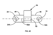
- FIG. 4C is a side elevation view of the link of FIG. 3 ;
- FIG. 5 is a perspective view of a second mounting bracket adapted to retain a second end of the tube-cable-router of FIG. 1 ;
- FIG. 5A is a front elevation view of the mounting bracket of FIG. 4 ;
- FIG. 5B is a top plan view of the mounting bracket of FIG. 4 ;
- FIG. 5C is a side elevation view of the mounting bracket of FIG. 4 ;
- FIG. 6 is an illustration of tubes carried with their longitudinal axes maintained in a plane containing the central radius of curvature of the tube-cable-router of FIG. 1 .
- FIG. 1 is a perspective assembly view of the flexible tube-cable-router 10 of the present invention constructed by assembling together an articulated number of individual dual-end link members 12 to form a two-ended chain of link members 12 .
- a first end mounting bracket terminator 14 is attached to one end of the chain of link members 12 and a second end mounting bracket terminator 16 is attached to the remaining end of the chain of link members 12 .
- FIG. 2 is a exploded perspective view of the flexible tube-cable-router 10 of FIG. 1 and illustrates how the two-ended chain of link members 12 is assembled by successively placing link hinge pins 18 into link hinge openings 20 and also placing terminator hinge pins 22 of first end mounting bracket terminator 14 into link hinge openings 20 as well as placing link hinge pins 18 into terminator hinge openings 24 of second end mounting bracket terminator 16 .
- Tube-cable-router 10 is provided with a number of unique features described hereinafter in order to facilitate assembly and secure clamping of a number of fluid tubes 78 (seen in FIG. 6 ) and a flat ribbon electrical cable 80 (seen in FIG. 6 ).
- FIG. 3 is a left front perspective view of the second end mounting bracket terminator 16 of FIG. 1 and illustrates a first pair of parallel open side tube grooves 26 formed in a second groove plane ( 26 P) in a base member 28 and having axis 26 A essentially parallel to the longitudinal direction of travel of flexible tube-cable-router 10 in order to carry a pair of liquid tubes 78 (in broken lines) therein.
- a second pair of parallel open side tube grooves 30 (best seen in FIG.
- 3A is also formed in the second groove plane ( 26 P) in a shoulder member 32 and having axis 30 A essentially parallel to the longitudinal direction of travel of flexible tube-cable-router 10 in order to carry another pair of liquid tubes 78 therein, shoulder member 32 flaring outwardly from base member 28 to simultaneously secure a flat ribbon electrical cable and a number of fluid tubes.
- a cable platform 34 is integrally superposed over base member 28 and comprises a transverse opening 36 defined by the upper surface 29 of base member 28 and the lower surface 37 of a flexible clasp 38 attached only at one end 39 to base member upper surface 29 .
- FIG. 3A shows how the transverse opening 36 is dimensioned to accept a flat ribbon cable 80 (shown in dashed lines) between base member upper surface 29 and flexible clasp 38 .
- the unattached end 41 of flexible clasp 38 is formed as a obliquely angled upwards step 42 . Best seen in FIG.
- a terminator tab member 44 extends laterally from each shoulder member 32 a distance beyond base member 28 and terminator hinge openings 24 of second end mounting bracket terminator 16 are formed therein.
- Upper surface 29 of base member 28 is seen in FIG. 3B as openly exposed between shoulder members 32 with a pair of mounting holes 45 formed therein and inline with the longitudinal direction of travel of flexible tube-cable-router 10 in order to allow securing flexible tube-cable-router 10 to an appropriate surface.
- FIG. 4 is a left perspective view of the link member 12 of FIG. 1 , each link member 12 having two parallel tab elements 46 extending in one direction from a rectangular shaped link base cross-member 47 (best seen in FIG. 4B ) having two parallel tongue elements 48 extending in an opposite direction from the cross-member.
- link hinge openings 24 are formed in recessed portions 46 R of tab elements 46 and transverse, cylindrical link hinge pins 18 are outwardly formed on tongue elements 48 .
- next adjacent link members 12 have overlapping sections and are joined by engaging the cylindrical hinge pins 18 of one link member 12 into the hinge openings 24 of a next adjacent link member 12 to pivot or rotate within a pivoting plane formed perpendicular to the central axis 18 A of hinge pins 18 and the central axis 24 A of hinge openings 24 ( FIGS. 4B and 4C ).
- the diametrical dimensions of hinge pins 18 and hinge openings 24 are chosen to have as little clearance as possible therebetween so that an assembly of interconnected link members 12 has high lateral stability.
- Link base cross-member 47 comprises a cut-away central portion 47 C (best seen in FIG. 4B ) with two open top parallel tube grooves 50 formed essentially parallel to the longitudinal direction of travel of flexible tube-cable-router 10 in order to carry a pair of liquid tubes therein.
- base cross-member 47 comprises outwardly opposed flange portions 47 F with two open side parallel tube grooves 52 formed essentially parallel to the longitudinal direction of travel of flexible tube-cable-router 10 in order to carry a pair of liquid tubes therein.
- FIG. 4A shows parallel tube grooves 50 and 52 as having their longitudinal axis 50 A and 52 A, respectively in a groove plane 52 P perpendicular to the pivoting plane PP ( FIG. 4B ).
- the flexible tube-cable-router 10 of the present invention is formed by assembling together an articulated number of individual dual-end links 12 with high lateral stability, the longitudinal axis of tubes carried by flexible tube-cable-router 10 are constantly maintained in a plane perpendicular to the groove plane and containing the central radius of curvature of tube-cable-router 10 . Because the longitudinal axis of tubes 78 carried by flexible tube-cable-router 10 are maintained in a plane containing the central radius of curvature of tube-cable-router 10 , “peristaltic-type” pumping action of fluid carried within such tubes is minimized as the curved section of tubes is moved in the direction of travel of tube-cable-router 10 . The elimination of peristaltic pumping, in combination with carrying flat ribbon cable 80 next described, is a key feature of the present invention.
- a link cable platform 54 is integrally superposed over link base cross-member 47 and comprising a transverse opening 56 defined by the upper surface 55 of link base cross-member 47 and the lower surface 59 of a flexible clasp 60 attached only at one end 61 to link base cross-member upper surface 55 .
- FIG. 4A shows how the transverse opening 56 is formed as a cross-sectional opening to accommodate a flat ribbon cable 80 (shown in dashed lines) between link base cross-member 47 and flexible clasp 58 .
- the unattached end 63 of flexible clasp 58 is formed as a obliquely angled upwards step 62 . Best seen in FIG.
- tab elements 46 having link hinge openings 24 formed in recessed portions 46 R thereof, extend laterally in one direction from rectangular shaped link base cross-member 47 and tongue elements 48 , having link hinge pins 18 are outwardly formed thereon, extend in an opposite direction from the cross-member.
- the lower surface 47 L of link base cross-member 47 is seen in FIG. 4B as openly exposed between flange portions 47 F with a pair of open bottom parallel tube grooves 50 formed essentially parallel to the longitudinal direction of travel of flexible tube-cable-router 10 in order to carry a pair of liquid tubes 78 therein.
- FIG. 5 is a left front perspective view of the first end mounting bracket terminator 14 of FIG. 1 and illustrates a first pair of parallel open side tube grooves 66 formed in a central region 68 C of a tube tower 68 and essentially parallel to the longitudinal direction of travel of flexible tube-cable-router 10 in order to carry a pair of liquid tubes therein.
- a second pair of parallel open side tube grooves 70 (also seen in FIG. 5A ) is formed in end regions 68 E of tube tower 68 and essentially parallel to the longitudinal direction of travel of flexible tube-cable-router 10 in order to carry a pair of liquid tubes 78 therein.
- the tube tower 68 is flexibly hinged at only one side to a vertical side wall 71 extending upwards from a mounting bracket terminator base 72 , being superposed thereover.
- An upwardly extending opposing sidewall 73 of mounting bracket terminator base 72 has an inclined upper surface 73 S (seen in FIG. 5A ) so that a transverse cross-sectional opening 77 is created between upper surface 73 S and tube tower 68 , enabling accommodation of a flat ribbon cable 80 (shown as dashed lines in FIG. 5A ) between tube tower 68 and mounting bracket terminator base 72 .
- a flat ribbon cable 80 shown as dashed lines in FIG. 5A
- first end mounting bracket terminator 14 comprises a frontward extending flare portion 72 F and tab elements 74 extending in an opposite direction from the frontward extending flare portion 72 F, tab elements 74 having link hinge pins 76 formed outwardly thereon.
- a mounting hole 72 H is formed in flare portion 72 F to allow securing assembled flexible tube-cable-router 10 to an appropriate surface.
- Cable-router 10 is illustrated in FIG. 6 as carrying one pair of liquid tubes 78 within the first pair of parallel open side tube grooves 26 formed in a base member 28 of mounting bracket terminator 16 and essentially parallel to the longitudinal direction of travel of flexible tube-cable-router 10 in addition to carrying another pair of tubes 78 within the second pair of parallel open side tube grooves 26 of mounting bracket terminator 16 of essentially parallel to the longitudinal direction of travel of flexible tube-cable-router 10 .
- FIG. 6 illustrates carrying one pair of liquid tubes 78 within the first pair of parallel open side tube grooves 26 formed in a base member 28 of mounting bracket terminator 16 and essentially parallel to the longitudinal direction of travel of flexible tube-cable-router 10 in addition to carrying another pair of tubes 78 within the second pair of parallel open side tube grooves 26 of mounting bracket terminator 16 of essentially parallel to the longitudinal direction of travel of flexible tube-cable-router 10 .
- FIG. 6 also shows parallel tube grooves 50 and 52 of link member 12 as having their longitudinal axis 50 A and 52 A, respectively in a groove plane perpendicular to the pivoting plane so that the longitudinal axis of tubes 78 are constantly maintained in a plane perpendicular to the groove plane and containing the central radius of curvature of tube-cable-router 10 .
- FIG. 6 illustrates bracket terminator 14 as carrying one pair of tubes 78 within the first pair of parallel open side tube grooves 66 and carrying another pair of tubes 78 within the second pair of parallel open side tube grooves 70 , both essentially parallel to the longitudinal direction of travel of flexible tube-cable-router 10 .
- a key feature of the present invention is maintaining the longitudinal axis of tubes 78 in a plane containing the central radius of curvature of tube-cable-router 10 so that “peristaltic-type” pumping action of fluid carried within such tubes 78 is minimized as the curved section of tubes 78 is moved in the direction of travel of tube-cable-router 10 .
- Cable-router 10 is further illustrated in FIG. 6 as carrying a single flat ribbon cable 80 within the transverse opening 36 defined by the upper surface 29 of base member 28 and the lower surface 37 of the flexible clasp 38 of the second end mounting bracket terminator 16 .
- the illustration of a single cable 80 is not intended to be limiting, as is obvious to an artesian, more than one such ribbon cable 80 may be carried within the transverse opening 36 with simple adjustments of the dimensions of upper surface 29 and lower surface 37 of clasp 38 .
- FIG. 6 illustrates bracket terminator 14 as carrying flat ribbon cable 80 within the transverse opening 77 defined by between tube tower 68 and mounting bracket terminator base 72 of bracket terminator 14 .
- FIG. 6 illustrates cable-router 10 as carrying flat ribbon cable 80 within transverse opening 56 defined by the upper surface 55 of link base cross-member 47 and the lower surface 59 of clasp 60 attached only at one end 61 to link base cross-member upper surface 55 of link member 12 .
- Cable-router 10 may be molded from any of a number of thermoplastic resin materials, including polyolefins, low density polyethylene, high impact polystyrene and polycarbonate. Clamp 10 can also be comprised of a combination of such resins. Preferably however, because of the necessity for precise dimensioning, an engineering plastic like acrylonitrile butadiene styrene, ABS, a copolymer of acrylonitrile, butadiene, and styrene may be advantageously employed. ABS plastics generally possess medium strength and performance and medium cost and are often used as the cost and performance dividing line between standard plastics (PVC, polyethylene, polystyrene, etc.) and engineering plastics (acrylic, nylon, acetal, etc.).
- transverse opening 36 can be adjusted to accommodate more than one ribbon cable 80 . Accordingly, while the present invention has been described herein in detail in relation to specific embodiments, it is to be understood that this disclosure is only illustrative and exemplary of the present invention and is made merely for purposes of providing a full and enabling disclosure of the invention. The foregoing disclosure is not intended or to be construed to limit the present invention or otherwise to exclude any such other embodiments, adaptations, variations, modifications and equivalent arrangements, the present invention being limited only by the claims appended hereto and the equivalents thereof.
Landscapes
- Engineering & Computer Science (AREA)
- General Engineering & Computer Science (AREA)
- Mechanical Engineering (AREA)
- Insulated Conductors (AREA)
- Supports For Pipes And Cables (AREA)
- Electric Cable Arrangement Between Relatively Moving Parts (AREA)
Abstract
Description
Claims (5)
Priority Applications (2)
| Application Number | Priority Date | Filing Date | Title |
|---|---|---|---|
| US11/384,986 US7240477B1 (en) | 2006-03-20 | 2006-03-20 | Flexible router for liquid tubes and electrical ribbon cables |
| PCT/US2007/064083 WO2007109510A2 (en) | 2006-03-20 | 2007-03-15 | A flexible router for liquid tubes and electrical ribbon cables |
Applications Claiming Priority (1)
| Application Number | Priority Date | Filing Date | Title |
|---|---|---|---|
| US11/384,986 US7240477B1 (en) | 2006-03-20 | 2006-03-20 | Flexible router for liquid tubes and electrical ribbon cables |
Publications (1)
| Publication Number | Publication Date |
|---|---|
| US7240477B1 true US7240477B1 (en) | 2007-07-10 |
Family
ID=38226917
Family Applications (1)
| Application Number | Title | Priority Date | Filing Date |
|---|---|---|---|
| US11/384,986 Expired - Fee Related US7240477B1 (en) | 2006-03-20 | 2006-03-20 | Flexible router for liquid tubes and electrical ribbon cables |
Country Status (2)
| Country | Link |
|---|---|
| US (1) | US7240477B1 (en) |
| WO (1) | WO2007109510A2 (en) |
Cited By (19)
| Publication number | Priority date | Publication date | Assignee | Title |
|---|---|---|---|---|
| WO2009049769A1 (en) * | 2007-10-10 | 2009-04-23 | Ondal Industrietechnik Gmbh | Suspension device |
| US20110146598A1 (en) * | 2009-12-22 | 2011-06-23 | Alstom Technology Ltd. | Cuff for boiler tube assembly and method of manufacture |
| US20110204190A1 (en) * | 2009-03-25 | 2011-08-25 | Dyden Corporation | Elongated structure for movable section |
| US20110240805A1 (en) * | 2010-04-02 | 2011-10-06 | Tsubakimoto Chain Co. | Multi-joint cable protection and guide device |
| DE102010032921A1 (en) * | 2010-07-30 | 2012-04-19 | Kabelschlepp Gmbh | Cable guide device with a ball-cable connection |
| US20130020290A1 (en) * | 2010-03-25 | 2013-01-24 | Trumpf Werkzeugmaschinen Gmbh + Co. Kg | Supply Line Routing Device |
| JP2014074440A (en) * | 2012-10-03 | 2014-04-24 | Tsubakimoto Chain Co | Cable protection and guiding device |
| US20180112739A1 (en) * | 2015-04-24 | 2018-04-26 | Hewlett Packard Enterprise Development Lp | Cable track |
| US20180128349A1 (en) * | 2015-04-27 | 2018-05-10 | Tsubakimoto Chain Co. | Long-object guide device and affixation member |
| EP3364070A1 (en) * | 2017-01-09 | 2018-08-22 | FMH Conveyors LLC | Roller chain outer plate links: arrangements, systems of use, and methods |
| US20180331523A1 (en) * | 2017-05-11 | 2018-11-15 | Hellermanntyton Gmbh | Cable channel module, modular assembly of cable channel modules and method of assembling a modular assembly |
| US10377327B1 (en) * | 2018-02-20 | 2019-08-13 | Yazaki Corporation | Curvature regulating member and power supply device |
| USD912364S1 (en) | 2017-01-09 | 2021-03-02 | Fmh Conveyors Llc | Roller chain outer plate link |
| US11171473B2 (en) * | 2018-11-01 | 2021-11-09 | Braitkorea Co., Ltd. | Support module for transmission line sleeve |
| USD980576S1 (en) | 2020-12-01 | 2023-03-07 | Fmh Conveyors Llc | Roller chain outer plate link |
| US11732841B2 (en) * | 2017-03-07 | 2023-08-22 | Stryker Corporation | Medical multi-link boom |
| WO2023189703A1 (en) * | 2022-03-30 | 2023-10-05 | 住友電装株式会社 | Movement-path-restricting component for electric cable, and path-restricting wire harness |
| US20240052652A1 (en) * | 2019-10-02 | 2024-02-15 | Technische Universität Dresden | Method for Producing a Textile Transverse Force Reinforcement, Supporting Device, Transverse Force Reinforcement, Concrete Component, and Yarn Placement File |
| US12460749B2 (en) | 2023-04-28 | 2025-11-04 | Hellermanntyton Corporation | Cradle mount fixings |
Families Citing this family (1)
| Publication number | Priority date | Publication date | Assignee | Title |
|---|---|---|---|---|
| DE202015101341U1 (en) | 2015-03-16 | 2015-03-20 | Igus Gmbh | Energy guiding chain with holder for an external line and corresponding receiving element |
Citations (14)
| Publication number | Priority date | Publication date | Assignee | Title |
|---|---|---|---|---|
| US4840023A (en) * | 1986-09-15 | 1989-06-20 | Tecno S.P.A. Mobili E Forniture Per Arredamento | Flexible cable guide with two-directional joints |
| US4852342A (en) | 1987-07-01 | 1989-08-01 | Mansign Engineering Limited | Cable handling chain |
| US4988838A (en) * | 1988-01-26 | 1991-01-29 | W. H Dunn & Son Limited | Line protecting apparatus |
| US5824957A (en) * | 1991-09-03 | 1998-10-20 | Technology Finance Corporation (Proprietary) Limited | Electrical cable containment |
| US5829243A (en) * | 1995-12-19 | 1998-11-03 | Hughes; Ceiriog | Replaceable tip cable handler |
| US5900586A (en) * | 1994-10-18 | 1999-05-04 | Smed Inc. | Cable carriers with individual sleeve units carried by a hose |
| US5980409A (en) | 1995-11-10 | 1999-11-09 | Igus Spritzgussteile Fur Die Industrie Gmbh | Energy transmission chain |
| US6170249B1 (en) | 1996-12-23 | 2001-01-09 | Igus Spritzgubbteile Fur Die Industrie Gmbh | Energy-supply chain |
| US6190277B1 (en) | 1997-07-10 | 2001-02-20 | Igus Spritzgussteile für die Industrie GmbH | Energy transmission chain |
| US6321524B1 (en) * | 1997-05-15 | 2001-11-27 | Hans Thyge Raunkjaer | System for the routing of bundles of wires |
| US6425238B1 (en) | 1998-05-05 | 2002-07-30 | Igus Spritzgussteile für die Industrie GmbH | Energy guiding chain |
| US6550233B2 (en) | 1999-04-19 | 2003-04-22 | Igus Spritzgussteile für die Industrie GmbH | Energy guiding chain |
| US6695014B2 (en) | 2000-02-16 | 2004-02-24 | Igus Spritzgubteile Fur Die Industrie Gmbh | Energy guiding chain |
| US6745555B2 (en) | 2001-04-23 | 2004-06-08 | Igus Spritzgussteile für die Industrie GmbH | Energy guiding chain |
-
2006
- 2006-03-20 US US11/384,986 patent/US7240477B1/en not_active Expired - Fee Related
-
2007
- 2007-03-15 WO PCT/US2007/064083 patent/WO2007109510A2/en not_active Ceased
Patent Citations (15)
| Publication number | Priority date | Publication date | Assignee | Title |
|---|---|---|---|---|
| US4840023A (en) * | 1986-09-15 | 1989-06-20 | Tecno S.P.A. Mobili E Forniture Per Arredamento | Flexible cable guide with two-directional joints |
| US4852342A (en) | 1987-07-01 | 1989-08-01 | Mansign Engineering Limited | Cable handling chain |
| US4988838A (en) * | 1988-01-26 | 1991-01-29 | W. H Dunn & Son Limited | Line protecting apparatus |
| US5824957A (en) * | 1991-09-03 | 1998-10-20 | Technology Finance Corporation (Proprietary) Limited | Electrical cable containment |
| US5900586A (en) * | 1994-10-18 | 1999-05-04 | Smed Inc. | Cable carriers with individual sleeve units carried by a hose |
| US5980409A (en) | 1995-11-10 | 1999-11-09 | Igus Spritzgussteile Fur Die Industrie Gmbh | Energy transmission chain |
| US5829243A (en) * | 1995-12-19 | 1998-11-03 | Hughes; Ceiriog | Replaceable tip cable handler |
| US6170249B1 (en) | 1996-12-23 | 2001-01-09 | Igus Spritzgubbteile Fur Die Industrie Gmbh | Energy-supply chain |
| US6321524B1 (en) * | 1997-05-15 | 2001-11-27 | Hans Thyge Raunkjaer | System for the routing of bundles of wires |
| US6190277B1 (en) | 1997-07-10 | 2001-02-20 | Igus Spritzgussteile für die Industrie GmbH | Energy transmission chain |
| US6425238B1 (en) | 1998-05-05 | 2002-07-30 | Igus Spritzgussteile für die Industrie GmbH | Energy guiding chain |
| US6612104B2 (en) | 1998-05-05 | 2003-09-02 | Igus Spritzgussteile Fur Die Industrie Gmbh | Energy guiding chain |
| US6550233B2 (en) | 1999-04-19 | 2003-04-22 | Igus Spritzgussteile für die Industrie GmbH | Energy guiding chain |
| US6695014B2 (en) | 2000-02-16 | 2004-02-24 | Igus Spritzgubteile Fur Die Industrie Gmbh | Energy guiding chain |
| US6745555B2 (en) | 2001-04-23 | 2004-06-08 | Igus Spritzgussteile für die Industrie GmbH | Energy guiding chain |
Cited By (33)
| Publication number | Priority date | Publication date | Assignee | Title |
|---|---|---|---|---|
| WO2009049769A1 (en) * | 2007-10-10 | 2009-04-23 | Ondal Industrietechnik Gmbh | Suspension device |
| US20100258694A1 (en) * | 2007-10-10 | 2010-10-14 | Ondal Industrietechnik Gmbh | Suspension device |
| US8950714B2 (en) * | 2009-03-25 | 2015-02-10 | Dyden Corporation | Elongated structure for movable section |
| US20110204190A1 (en) * | 2009-03-25 | 2011-08-25 | Dyden Corporation | Elongated structure for movable section |
| CN102379074B (en) * | 2009-03-25 | 2016-01-20 | 大电株式会社 | Strip material for movable parts |
| US20110146598A1 (en) * | 2009-12-22 | 2011-06-23 | Alstom Technology Ltd. | Cuff for boiler tube assembly and method of manufacture |
| US20130020290A1 (en) * | 2010-03-25 | 2013-01-24 | Trumpf Werkzeugmaschinen Gmbh + Co. Kg | Supply Line Routing Device |
| US20110240805A1 (en) * | 2010-04-02 | 2011-10-06 | Tsubakimoto Chain Co. | Multi-joint cable protection and guide device |
| US8882052B2 (en) * | 2010-04-02 | 2014-11-11 | Tsubakimoto Chain Co. | Multi-joint cable protection and guide device |
| DE102010032921A1 (en) * | 2010-07-30 | 2012-04-19 | Kabelschlepp Gmbh | Cable guide device with a ball-cable connection |
| JP2014074440A (en) * | 2012-10-03 | 2014-04-24 | Tsubakimoto Chain Co | Cable protection and guiding device |
| US10190658B2 (en) * | 2015-04-24 | 2019-01-29 | Hewlett Packard Enterprise Development Lp | Cable track |
| US20180112739A1 (en) * | 2015-04-24 | 2018-04-26 | Hewlett Packard Enterprise Development Lp | Cable track |
| US10221919B2 (en) * | 2015-04-27 | 2019-03-05 | Tsubakimoto Chain Co. | Long-object guide device and affixation member |
| US20180128349A1 (en) * | 2015-04-27 | 2018-05-10 | Tsubakimoto Chain Co. | Long-object guide device and affixation member |
| USD1053494S1 (en) | 2017-01-09 | 2024-12-03 | Fmh Conveyors Llc | Roller chain outer plate link |
| EP3364070A1 (en) * | 2017-01-09 | 2018-08-22 | FMH Conveyors LLC | Roller chain outer plate links: arrangements, systems of use, and methods |
| US10533646B2 (en) | 2017-01-09 | 2020-01-14 | Fmh Conveyors Llc | Roller chain outer plate links: arrangements, systems of use, and methods |
| USD912364S1 (en) | 2017-01-09 | 2021-03-02 | Fmh Conveyors Llc | Roller chain outer plate link |
| US11054004B2 (en) | 2017-01-09 | 2021-07-06 | Fmh Conveyors Llc | Roller chain outer plate links: arrangements, systems of use, and methods |
| US12540705B2 (en) | 2017-03-07 | 2026-02-03 | Stryker Corporation | Medical multi-link boom |
| US11732841B2 (en) * | 2017-03-07 | 2023-08-22 | Stryker Corporation | Medical multi-link boom |
| US10680421B2 (en) * | 2017-05-11 | 2020-06-09 | Hellermanntyton Gmbh | Cable channel module, modular assembly of cable channel modules and method of assembling a modular assembly |
| US20180331523A1 (en) * | 2017-05-11 | 2018-11-15 | Hellermanntyton Gmbh | Cable channel module, modular assembly of cable channel modules and method of assembling a modular assembly |
| US10377327B1 (en) * | 2018-02-20 | 2019-08-13 | Yazaki Corporation | Curvature regulating member and power supply device |
| US11171473B2 (en) * | 2018-11-01 | 2021-11-09 | Braitkorea Co., Ltd. | Support module for transmission line sleeve |
| US20240052652A1 (en) * | 2019-10-02 | 2024-02-15 | Technische Universität Dresden | Method for Producing a Textile Transverse Force Reinforcement, Supporting Device, Transverse Force Reinforcement, Concrete Component, and Yarn Placement File |
| US12234658B2 (en) * | 2019-10-02 | 2025-02-25 | Maria Garibaldi | Method for producing a textile transverse force reinforcement, supporting device, transverse force reinforcement, concrete component, and yarn placement file |
| USD1051545S1 (en) | 2020-12-01 | 2024-11-12 | Fmh Conveyors Llc | Roller chain outer plate link |
| USD980576S1 (en) | 2020-12-01 | 2023-03-07 | Fmh Conveyors Llc | Roller chain outer plate link |
| JP2023147412A (en) * | 2022-03-30 | 2023-10-13 | 住友電装株式会社 | Movable route regulating parts and route regulating wire harnesses for electric wires |
| WO2023189703A1 (en) * | 2022-03-30 | 2023-10-05 | 住友電装株式会社 | Movement-path-restricting component for electric cable, and path-restricting wire harness |
| US12460749B2 (en) | 2023-04-28 | 2025-11-04 | Hellermanntyton Corporation | Cradle mount fixings |
Also Published As
| Publication number | Publication date |
|---|---|
| WO2007109510A2 (en) | 2007-09-27 |
| WO2007109510A3 (en) | 2008-10-16 |
Similar Documents
| Publication | Publication Date | Title |
|---|---|---|
| US7240477B1 (en) | Flexible router for liquid tubes and electrical ribbon cables | |
| WO2007109495A2 (en) | Liquid tube and electrical clamp with locking features | |
| EP1883475B1 (en) | Sample tube holder | |
| US5171538A (en) | Reagent supply system for a medical analytical instrument | |
| CA2015558C (en) | Air detector for use in infusion pump | |
| US8802037B2 (en) | Sample well strip | |
| US20140093438A1 (en) | Container holder and container carrier | |
| US20140127828A1 (en) | Reaction vessel, assay device, and measuring method | |
| JP6740281B2 (en) | Switches for transport lines that transport laboratory diagnostic container carriers | |
| WO2012134093A2 (en) | Integrated collecting and dispensing device | |
| US4844870A (en) | Liquid monitoring | |
| EP0743095A1 (en) | Small volume disposable pipette tip | |
| AU2002335887A1 (en) | Sample well strip | |
| CA2555519C (en) | Photometric in plane detection | |
| EP2094388B1 (en) | A well plate for holding a sample during analysis | |
| JP7297045B2 (en) | Connection joints for connecting components of laboratory automation systems | |
| US20060280657A1 (en) | Snap fit sensor mounting bracket | |
| EP0280473B1 (en) | Sample transfer device | |
| CN107037227B (en) | Regulating system | |
| CN215087262U (en) | Pneumatic pipettor with independent moving device | |
| JP2008064554A (en) | Sample container adapter and sample container rack | |
| US20260084158A1 (en) | Device for holding sample vessels and a kit comprising the device | |
| JPH06180321A (en) | Pipette needle coupling device | |
| CN119534822A (en) | Kit and blood cell analyzer | |
| IES85039Y1 (en) | A well plate for holding a sample during analysis and a method for analysing a sample |
Legal Events
| Date | Code | Title | Description |
|---|---|---|---|
| AS | Assignment |
Owner name: DADE BEHRING INC., ILLINOIS Free format text: ASSIGNMENT OF ASSIGNORS INTEREST;ASSIGNORS:DUNFEE, WILLIAM D.;HENDERSON, DAVID G.;WEITKAMP, THOMAS E.;REEL/FRAME:017491/0662 Effective date: 20060313 |
|
| AS | Assignment |
Owner name: SIEMENS HEALTHCARE DIAGNOSTICS INC., ILLINOIS Free format text: MERGER;ASSIGNOR:DADE BEHRING INC.;REEL/FRAME:020690/0530 Effective date: 20071231 Owner name: SIEMENS HEALTHCARE DIAGNOSTICS INC.,ILLINOIS Free format text: MERGER;ASSIGNOR:DADE BEHRING INC.;REEL/FRAME:020690/0530 Effective date: 20071231 |
|
| FPAY | Fee payment |
Year of fee payment: 4 |
|
| REMI | Maintenance fee reminder mailed | ||
| LAPS | Lapse for failure to pay maintenance fees | ||
| STCH | Information on status: patent discontinuation |
Free format text: PATENT EXPIRED DUE TO NONPAYMENT OF MAINTENANCE FEES UNDER 37 CFR 1.362 |
|
| STCH | Information on status: patent discontinuation |
Free format text: PATENT EXPIRED DUE TO NONPAYMENT OF MAINTENANCE FEES UNDER 37 CFR 1.362 |
|
| FP | Lapsed due to failure to pay maintenance fee |
Effective date: 20150710 |