US7237522B2 - Intake system for combustion engine - Google Patents
Intake system for combustion engine Download PDFInfo
- Publication number
- US7237522B2 US7237522B2 US11/207,224 US20722405A US7237522B2 US 7237522 B2 US7237522 B2 US 7237522B2 US 20722405 A US20722405 A US 20722405A US 7237522 B2 US7237522 B2 US 7237522B2
- Authority
- US
- United States
- Prior art keywords
- suction duct
- combustion engine
- air
- intake system
- air cleaner
- Prior art date
- Legal status (The legal status is an assumption and is not a legal conclusion. Google has not performed a legal analysis and makes no representation as to the accuracy of the status listed.)
- Expired - Lifetime
Links
Images


Classifications
-
- F—MECHANICAL ENGINEERING; LIGHTING; HEATING; WEAPONS; BLASTING
- F02—COMBUSTION ENGINES; HOT-GAS OR COMBUSTION-PRODUCT ENGINE PLANTS
- F02M—SUPPLYING COMBUSTION ENGINES IN GENERAL WITH COMBUSTIBLE MIXTURES OR CONSTITUENTS THEREOF
- F02M69/00—Low-pressure fuel-injection apparatus ; Apparatus with both continuous and intermittent injection; Apparatus injecting different types of fuel
- F02M69/04—Injectors peculiar thereto
- F02M69/042—Positioning of injectors with respect to engine, e.g. in the air intake conduit
- F02M69/043—Positioning of injectors with respect to engine, e.g. in the air intake conduit for injecting into the intake conduit upstream of an air throttle valve
-
- F—MECHANICAL ENGINEERING; LIGHTING; HEATING; WEAPONS; BLASTING
- F02—COMBUSTION ENGINES; HOT-GAS OR COMBUSTION-PRODUCT ENGINE PLANTS
- F02B—INTERNAL-COMBUSTION PISTON ENGINES; COMBUSTION ENGINES IN GENERAL
- F02B17/00—Engines characterised by means for effecting stratification of charge in cylinders
-
- F—MECHANICAL ENGINEERING; LIGHTING; HEATING; WEAPONS; BLASTING
- F02—COMBUSTION ENGINES; HOT-GAS OR COMBUSTION-PRODUCT ENGINE PLANTS
- F02B—INTERNAL-COMBUSTION PISTON ENGINES; COMBUSTION ENGINES IN GENERAL
- F02B31/00—Modifying induction systems for imparting a rotation to the charge in the cylinder
- F02B31/08—Modifying induction systems for imparting a rotation to the charge in the cylinder having multiple air inlets
- F02B31/087—Modifying induction systems for imparting a rotation to the charge in the cylinder having multiple air inlets having three or more inlet valves
-
- F—MECHANICAL ENGINEERING; LIGHTING; HEATING; WEAPONS; BLASTING
- F02—COMBUSTION ENGINES; HOT-GAS OR COMBUSTION-PRODUCT ENGINE PLANTS
- F02D—CONTROLLING COMBUSTION ENGINES
- F02D9/00—Controlling engines by throttling air or fuel-and-air induction conduits or exhaust conduits
- F02D9/08—Throttle valves specially adapted therefor; Arrangements of such valves in conduits
- F02D9/10—Throttle valves specially adapted therefor; Arrangements of such valves in conduits having pivotally-mounted flaps
- F02D9/1065—Mechanical control linkage between an actuator and the flap, e.g. including levers, gears, springs, clutches, limit stops of the like
-
- F—MECHANICAL ENGINEERING; LIGHTING; HEATING; WEAPONS; BLASTING
- F02—COMBUSTION ENGINES; HOT-GAS OR COMBUSTION-PRODUCT ENGINE PLANTS
- F02M—SUPPLYING COMBUSTION ENGINES IN GENERAL WITH COMBUSTIBLE MIXTURES OR CONSTITUENTS THEREOF
- F02M35/00—Combustion-air cleaners, air intakes, intake silencers, or induction systems specially adapted for, or arranged on, internal-combustion engines
- F02M35/10—Air intakes; Induction systems
- F02M35/10006—Air intakes; Induction systems characterised by the position of elements of the air intake system in direction of the air intake flow, i.e. between ambient air inlet and supply to the combustion chamber
- F02M35/10026—Plenum chambers
- F02M35/10039—Intake ducts situated partly within or on the plenum chamber housing
-
- F—MECHANICAL ENGINEERING; LIGHTING; HEATING; WEAPONS; BLASTING
- F02—COMBUSTION ENGINES; HOT-GAS OR COMBUSTION-PRODUCT ENGINE PLANTS
- F02M—SUPPLYING COMBUSTION ENGINES IN GENERAL WITH COMBUSTIBLE MIXTURES OR CONSTITUENTS THEREOF
- F02M35/00—Combustion-air cleaners, air intakes, intake silencers, or induction systems specially adapted for, or arranged on, internal-combustion engines
- F02M35/10—Air intakes; Induction systems
- F02M35/1015—Air intakes; Induction systems characterised by the engine type
- F02M35/10177—Engines having multiple fuel injectors or carburettors per cylinder
-
- F—MECHANICAL ENGINEERING; LIGHTING; HEATING; WEAPONS; BLASTING
- F02—COMBUSTION ENGINES; HOT-GAS OR COMBUSTION-PRODUCT ENGINE PLANTS
- F02M—SUPPLYING COMBUSTION ENGINES IN GENERAL WITH COMBUSTIBLE MIXTURES OR CONSTITUENTS THEREOF
- F02M35/00—Combustion-air cleaners, air intakes, intake silencers, or induction systems specially adapted for, or arranged on, internal-combustion engines
- F02M35/10—Air intakes; Induction systems
- F02M35/10209—Fluid connections to the air intake system; their arrangement of pipes, valves or the like
- F02M35/10216—Fuel injectors; Fuel pipes or rails; Fuel pumps or pressure regulators
-
- F—MECHANICAL ENGINEERING; LIGHTING; HEATING; WEAPONS; BLASTING
- F02—COMBUSTION ENGINES; HOT-GAS OR COMBUSTION-PRODUCT ENGINE PLANTS
- F02M—SUPPLYING COMBUSTION ENGINES IN GENERAL WITH COMBUSTIBLE MIXTURES OR CONSTITUENTS THEREOF
- F02M35/00—Combustion-air cleaners, air intakes, intake silencers, or induction systems specially adapted for, or arranged on, internal-combustion engines
- F02M35/10—Air intakes; Induction systems
- F02M35/104—Intake manifolds
- F02M35/108—Intake manifolds with primary and secondary intake passages
-
- F—MECHANICAL ENGINEERING; LIGHTING; HEATING; WEAPONS; BLASTING
- F02—COMBUSTION ENGINES; HOT-GAS OR COMBUSTION-PRODUCT ENGINE PLANTS
- F02M—SUPPLYING COMBUSTION ENGINES IN GENERAL WITH COMBUSTIBLE MIXTURES OR CONSTITUENTS THEREOF
- F02M35/00—Combustion-air cleaners, air intakes, intake silencers, or induction systems specially adapted for, or arranged on, internal-combustion engines
- F02M35/16—Combustion-air cleaners, air intakes, intake silencers, or induction systems specially adapted for, or arranged on, internal-combustion engines characterised by use in vehicles
- F02M35/162—Motorcycles; All-terrain vehicles, e.g. quads, snowmobiles; Small vehicles, e.g. forklifts
-
- F—MECHANICAL ENGINEERING; LIGHTING; HEATING; WEAPONS; BLASTING
- F02—COMBUSTION ENGINES; HOT-GAS OR COMBUSTION-PRODUCT ENGINE PLANTS
- F02M—SUPPLYING COMBUSTION ENGINES IN GENERAL WITH COMBUSTIBLE MIXTURES OR CONSTITUENTS THEREOF
- F02M9/00—Carburettors having air or fuel-air mixture passage throttling valves other than of butterfly type; Carburettors having fuel-air mixing chambers of variable shape or position
- F02M9/08—Carburettors having air or fuel-air mixture passage throttling valves other than of butterfly type; Carburettors having fuel-air mixing chambers of variable shape or position having throttling valves rotatably mounted in the passage
-
- F—MECHANICAL ENGINEERING; LIGHTING; HEATING; WEAPONS; BLASTING
- F02—COMBUSTION ENGINES; HOT-GAS OR COMBUSTION-PRODUCT ENGINE PLANTS
- F02M—SUPPLYING COMBUSTION ENGINES IN GENERAL WITH COMBUSTIBLE MIXTURES OR CONSTITUENTS THEREOF
- F02M35/00—Combustion-air cleaners, air intakes, intake silencers, or induction systems specially adapted for, or arranged on, internal-combustion engines
- F02M35/02—Air cleaners
-
- Y—GENERAL TAGGING OF NEW TECHNOLOGICAL DEVELOPMENTS; GENERAL TAGGING OF CROSS-SECTIONAL TECHNOLOGIES SPANNING OVER SEVERAL SECTIONS OF THE IPC; TECHNICAL SUBJECTS COVERED BY FORMER USPC CROSS-REFERENCE ART COLLECTIONS [XRACs] AND DIGESTS
- Y02—TECHNOLOGIES OR APPLICATIONS FOR MITIGATION OR ADAPTATION AGAINST CLIMATE CHANGE
- Y02T—CLIMATE CHANGE MITIGATION TECHNOLOGIES RELATED TO TRANSPORTATION
- Y02T10/00—Road transport of goods or passengers
- Y02T10/10—Internal combustion engine [ICE] based vehicles
- Y02T10/12—Improving ICE efficiencies
Definitions
- the present invention relates to an intake system for a combustion engine, particularly that used in a motorcycle.
- first and second fuel injectors are employed in each of intake passages leading to respective engine cylinders and are operated simultaneously during a high power operation.
- the first and second fuel injectors are positioned downstream of a throttle valve in a throttle body and upstream of an suction duct protruding into an air cleaner forming a part of the intake passage, respectively.
- the distance between an injection port of the second fuel injector and a combustion chamber of the engine is set relatively long by positioning the second fuel injector within the air cleaner distant from the combustion chamber. This structural feature is effective to facilitate a fine atomization of fuel being injected into the combustion chamber.
- the fuel intake passages in the conventional intake system are limited as to their size and shape.
- the second fuel injector is arranged above (upstream of) the suction duct that protrudes into the air cleaner as discussed above, the air intake space above the suction duct is limited, resulting in the intake efficiency being lowered. See, for example, the Japanese Laid-open Patent Publication No. 2004-60552.
- the present invention has an object to increase the intake efficiency in an intake system of a combustion engine including at least one fuel injector disposed in an intake passage.
- the present invention provides an intake system for a combustion engine, which includes an intake passage, an suction duct protruding into the intake passage to communicate therewith and having front and rear wall areas, and a fuel injector positioned upstream of the suction duct for injecting fuel into the suction duct.
- the rear wall area of the suction duct has a height greater than that of the front wall area.
- the height of the rear wall area of the suction duct is chosen to be greater than that of the front wall area, the air tending to flow over the suction duct can be more sucked into the suction duct as deflected by the rear wall area higher than the front wall area, as compared with the suction duct having the rear wall area and the front wall area of the same height.
- the effective opening area of the suction duct (the intake area through which the air flows into the suction duct) can increase.
- more air can be introduced into the suction duct, resulting in increase of the intake efficiency.
- front and rear used in connection with the respective wall areas of the suction duct are in relation to the geometry of the motorcycle.
- front may represent an upstream region with respect to the direction of flow of the air to be sucked into the suction duct.
- an air cleaner is provided in the intake passage and has an air delivery area.
- the suction duct is disposed in the air delivery area of the air cleaner. Positioning of the suction duct within the air delivery area of the air cleaner is effective to introduce more air into the suction duct from the air delivery area.
- the air cleaner may include a box-like cleaner casing having top and bottom walls and the fuel injector and the suction duct may be mounted on the top and bottom walls of the cleaner casing, respectively.
- the rear wall area of the suction duct has an upper end held substantially level with or higher than a fuel injection port of the fuel injector. According to this structural feature, the fuel injected from the fuel injection port is prevented from being carried rearward by the air beyond the suction duct, resulting in little leakage of the fuel from the suction duct.
- the suction duct has a pair of side wall areas connecting between the front and rear wall areas.
- Each of the side wall areas has an upper end curved downwardly thereof to form a dent edge.
- the suction duct may have an upstream duct portion that is curved to incline forwardly to have an inlet opening directed forwardly upwardly with respect to the direction of flow of the air. According to this structural feature, the air can be smoothly introduced into the suction duct.
- FIG. 1 is a side view of a motorcycle equipped with an intake system for a combustion engine according to a first preferred embodiment of the present invention
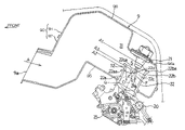
- FIG. 2 is a fragmentary side view showing the intake system for the combustion engine and its surroundings;
- FIG. 3 is a fragmentary longitudinal sectional view showing an essential portion of the intake system
- FIG. 4 is a fragmentary longitudinal sectional view of an essential portion of the intake system, according to a second preferred embodiment of the present invention.
- FIG. 5 is a fragmentary longitudinal sectional view of an essential portion of the intake system according to a third preferred embodiment of the present invention.
- FIG. 1 schematically illustrates a side view of a motorcycle according to a first preferred embodiment of the present invention, showing an entire structure thereof.
- the motorcycle includes a motorcycle frame structure FR having a head tube 10 formed at a front portion of the motorcycle frame structure FR.
- a steering front fork assembly 3 is pivotally supported by the head tube 10 .
- a front wheel 4 is rotatably supported by a lower end of the fork assembly 3 .
- the motorcycle frame structure FR has a generally lower intermediate portion provided with swingarm brackets 5 , on which a swingarm 6 is pivotally supported for movement up and down.
- a rear wheel 7 is rotatably supported by the swingarm 6 .
- a combustion engine E is mounted on a generally intermediate portion of the motorcycle frame structure FR and forwardly of the swingarm brackets 5 and has a drive output shaft (not shown) which is drivingly coupled with the rear wheel 7 through a drive transmission chain (not shown) in a manner well known to those skilled in the art.
- An upper bracket 30 supporting an upper portion of the front fork assembly 3 has a steering handlebar 8 mounted thereon.
- the motorcycle frame structure FR includes a main frame 2 so forked rearward from the head tube 10 as to form a pair of main frame half portions 2 a and 2 a ( FIG. 2 ).
- a fuel tank 11 is mounted on a generally upper intermediate portion of the main frame 2 .
- An air cleaner 9 is carried by the main frame 2 below the fuel tank 11 and above the combustion engine E.
- a pair of seat rails 14 and a pair of reinforcement rails 15 are fixed to a rear portion of the main frame 2 .
- a rider seat 16 is mounted on the pair of seat rails 14 .
- a single rear suspension unit 17 is arranged between the motorcycle frame structure FR and the swingarm 6 .
- a fairing 18 made of a synthetic resin is mounted on a front portion of the motorcycle frame structure FR so as to cover a front portion of the main frame 2 anterior to the handlebar 8 and also cover a lower portion and lateral portions of the combustion engine E.
- a front mudguard or fender 19 is arranged below a front portion of the fairing 18 so as to extend over the front wheel 4 .
- the fairing 18 has a front face formed with an air intake opening 18 a.
- An air intake duct 13 is arranged to extend between the air intake opening 18 a and an air inlet 9 a of the air cleaner 9 for introducing air A rearward from the air intake opening 18 a to the air cleaner 9 by way of the air inlet 9 a.
- This air intake duct 13 forms an upstream passage portion 12 a of an air intake passage 12 upstream of the air cleaner 9 with respect to the direction of flow of the air A towards the air cleaner 9 .
- the air cleaner 9 has an air delivery area where a suction duct 22 leading to an intake port (not shown) of the combustion engine E protrudes into the air cleaner 9 .
- a fuel injector 21 is arranged upstream of the suction duct 22 protruding into the air cleaner 9 . It is to be noted that each of the fuel injector 21 and the suction duct 22 is employed in a number equal to the number of the cylinders employed in the combustion engine E and, accordingly, in the case of the combustion engine E having two cylinders, two fuel injectors 21 and two suction ducts 22 are employed correspondingly.
- FIG. 2 illustrates a fragmentary side view of an intake system for the combustion engine E and its surroundings.
- FIG. 3 illustrates a fragmentary longitudinal sectional view showing an essential portion of the intake system.
- the air cleaner 9 is disposed between the main frame half portions 2 a and 2 a forming the main frame 2 .
- This air cleaner 9 includes a box-like cleaner casing 90 of two-piece construction including upper and lower casing halves 91 and 92 joined together.
- a cleaner element 32 for purifying the air A is replaceably accommodated within the cleaner casing 90 .
- the suction duct 22 is disposed downstream of the cleaner element 32 , that is, disposed within a clean chamber (delivery area) 31 defined within the cleaner casing 90 .
- the suction duct 22 extends through a bottom wall of the air cleaner 9 , that is, a bottom wall 95 of the lower casing half 92 of the cleaner casing 90 for support.
- This suction duct 22 is communicated with the intake port (not shown) of the combustion engine E through a passage defined within a throttle body 25 .
- the air intake duct 13 , the air cleaner 9 , the suction duct 22 and the throttle body 25 form the air intake passage 12 , with the suction duct 22 and the throttle body 25 forming a downstream passage portion 12 b of the air intake passage 12 with respect to the air cleaner 9 .
- the illustrated combustion engine E utilizes a so-called double injector system including a first or primary fuel injector 20 and a second or auxiliary fuel injector 21 .
- the first fuel injector 20 is disposed downstream of a throttle valve (not shown), that is positioned downstream of the suction duct 22 .
- the second fuel injector 21 is disposed at a step portion 96 a ( FIG. 3 ) of an upper wall 96 of the air cleaner 9 to confront an inlet opening 22 d of the suction duct 22 .
- the first and second fuel injectors 20 and 21 are controlled by a fuel injection control unit (not shown) that controls fuel injecting timing and amount of fuel to be injected in dependence on the load imposed on the combustion engine E.
- a fuel injection control unit (not shown) that controls fuel injecting timing and amount of fuel to be injected in dependence on the load imposed on the combustion engine E.
- fuel F can be injected only from the first injector 20
- fuel F can be injected simultaneously from the first and second fuel injectors 20 and 21 .
- the suction duct 22 in the illustrated embodiment has a cross-sectional area, taken in a direction perpendicular to the longitudinal axis C of the suction duct 22 , which represents an elliptical shape having a major axis lying in a forward and rearward direction, that is, in a direction generally parallel to the longitudinal sense of the main frame assembly 2 .
- the neighboring suction ducts 22 and 22 can be spaced advantageously a considerable distance sufficient to allow a stream of air to flow smoothly without being disturbed by those suction ducts 22 and 22 .
- the suction duct 22 extending into the clean chamber 31 through the bottom wall 95 includes a front wall area 22 a confronting the air A, a rear wall area 22 b opposite to the front wall area 22 a, and a pair of side wall areas 22 c continued from and connecting the front and rear wall areas 22 a and 22 b.
- the height of the rear wall area 22 b is chosen to be greater than that of the front wall area 22 a, with an upper end 22 ba of the rear wall area 22 b positioned at a level higher than the level of an fuel injection port 21 a of the fuel injector 21 .
- the fuel injection port 21 a of the fuel injector 21 when viewed from laterally as shown in FIG.
- each of the side wall areas 22 c connecting the front and rear side wall areas 22 a and 22 b has an upper end 22 ca that is smoothly curved downwardly or axially inwardly to form a dent edge.
- the suction duct 22 has its longitudinal axis lying perpendicular to the bottom wall 95 of the cleaner casing 90 and also perpendicular to respective directions of flow of the purified airs A 1 to A 3 within the clean chamber 31 . It is to be noted that the cleaner element 32 shown in FIG. 2 is not shown in FIG. 3 for the sake of brevity.
- the intake space S above the suction duct 22 becomes small.
- the rear wall area 22 b of the suction duct 22 is so chosen to have a height greater than that of the front wall area 22 a, the effective opening area of the suction duct 22 (the intake area through which the purified air flows into the suction duct 22 ) can increase in effect as compared with the suction duct having the rear wall area 22 b and the front wall area 22 a of the same height.
- the air A 1 tending to flow over the suction duct 52 in the case of the conventional suction duct 52 having the rear wall area 22 b and the front wall area 22 a of the same height as shown by the double-dotted line in FIG. 3 , can be deflected in contact with a portion of the rear wall area 22 b adjacent the upper end 22 ba so as to flow into the suction duct 22 as a result of the increased height of the rear wall area 22 b.
- the air A 2 tending to collide against the front wall 22 a of the suction duct 22 can also be guided straightforward into the suction duct 22 .
- the effective opening area of the suction duct 22 can increase enough to allow the airs A 1 and A 2 to be sucked into the suction duct 22 , resulting in increasing the intake efficiency.
- the upper end 22 ba of the rear wall area 22 b is positioned at a level higher than that of the fuel injection port 21 a of the fuel injector 21 , the fuel F injected from the fuel injection port 21 a is prevented from being carried rearward by the airs A 1 to A 3 beyond the rear wall area 22 b, resulting in little leakage of the fuel F from the suction duct 22 .
- the air A 3 flowing laterally of the suction duct 22 with respect to the direction of flow within the air cleaner 9 (the intake passage 12 ) can also be sucked into the suction duct 22 and, therefore, the increased amount of air can advantageously be sucked into the suction duct 22 , resulting in a further increase of the intake efficiency.
- FIG. 4 schematically illustrates a view similar to FIG. 3 , showing the intake system according to the second preferred embodiment of the present invention.
- the upper end 22 ca of each of the side wall areas 22 c of the suction duct 22 extends straight in contrast to the curved configuration employed in the first embodiment. More specifically, when viewed laterally, the upper end 22 ca connects the upper end 22 aa of the front wall area 22 a and the upper end 22 ba of the rear wall area 22 b while extending straight therebetween.
- the effective opening area of the suction duct 22 (the intake surface area) can increase in effect, as compared with the suction duct having the rear wall area 22 b and the front wall area 22 a of the same height. Accordingly, a substantially large amount of air can be sucked into the suction duct 22 , resulting in increase of the intake efficiency.
- the upper end 22 ba of the rear wall area 22 b is positioned at a level higher than that of the fuel injection port 21 a of the fuel injector 21 , the fuel F injected from the fuel injection port 21 a is prevented from being carried rearward by the airs A 1 to A 3 beyond the rear wall area 22 b, resulting in little leakage of the fuel F from the suction duct 22 .
- cleaner element 32 shown in FIG. 2 is not shown even in FIG. 4 for the sake of brevity.
- FIG. 5 illustrates a view similar to FIG. 4 , showing the fuel intake system according to a third preferred embodiment of the present invention.
- This intake system is similar to that of the second embodiment in that the upper end 22 ca of the side wall area 22 c connects straight the upper end 22 aa of the front wall area 22 a and the upper end 22 ba of the rear wall area 22 b.
- the suction duct 22 has its longitudinal axis C in the upstream duct portion smoothly curved or inclined forwardly so that the inlet opening 22 d directs forwardly and upwardly to slantwisely encounter to the direction of flow of the air A. Accordingly, the airs A 1 and A 2 can be smoothly introduced into the suction duct 22 .
- the rear wall area 22 b is chosen to have a height greater than that of the front wall area 22 a and the upper end 22 ba of the rear wall area 22 is held at a level higher than that of the fuel injection port 21 a of the fuel injector 21 . Accordingly, not only can the amount of the air being introduced into the suction duct 22 be increased with the consequent increase in intake efficiency, but also the fuel F injected from the fuel injection port 21 a is prevented from being carried rearward by the airs A 1 and A 2 beyond the rear wall area 22 b, resulting in little leakage of the fuel F from the suction duct 22 .
- the suction ducts 22 communicated with respective engine cylinders may be arranged to have different passage lengths chosen in consideration of, for example, intake inertias. By so doing, the intake efficiency can be further increased.
- the suction duct 22 has been shown and described as having an elliptical cross-sectional area lying perpendicular to the longitudinal axis thereof, the cross-sectional shape of the suction duct 22 may not be always limited to the elliptical shape, but may have, for example, a round cross-sectional shape, an oval shape, a rectangular shape, a rhomboidal shape or any other shape.
- the upper end 22 ba of the rear wall area 22 b of the suction duct 22 has been described as held at the level higher than that of the fuel injection port 21 a of the fuel injector 21
- the upper end 22 ba may be held substantially at a level with or held at a level slightly higher than that of the fuel injection port 21 a of the fuel injector 21 , provided that the fuel F injected from the fuel injection port 21 a will not leak outside the suction duct 22 .
Landscapes
- Engineering & Computer Science (AREA)
- Chemical & Material Sciences (AREA)
- Combustion & Propulsion (AREA)
- Mechanical Engineering (AREA)
- General Engineering & Computer Science (AREA)
- Fuel-Injection Apparatus (AREA)
Abstract
Description
Claims (9)
Applications Claiming Priority (4)
| Application Number | Priority Date | Filing Date | Title |
|---|---|---|---|
| JP2004245295 | 2004-08-25 | ||
| JP2004-245295 | 2004-08-25 | ||
| JP2004-304702 | 2004-10-19 | ||
| JP2004304702A JP4464243B2 (en) | 2004-08-25 | 2004-10-19 | Engine intake system |
Publications (2)
| Publication Number | Publication Date |
|---|---|
| US20060042603A1 US20060042603A1 (en) | 2006-03-02 |
| US7237522B2 true US7237522B2 (en) | 2007-07-03 |
Family
ID=35941269
Family Applications (1)
| Application Number | Title | Priority Date | Filing Date |
|---|---|---|---|
| US11/207,224 Expired - Lifetime US7237522B2 (en) | 2004-08-25 | 2005-08-19 | Intake system for combustion engine |
Country Status (2)
| Country | Link |
|---|---|
| US (1) | US7237522B2 (en) |
| JP (1) | JP4464243B2 (en) |
Cited By (4)
| Publication number | Priority date | Publication date | Assignee | Title |
|---|---|---|---|---|
| US20090265078A1 (en) * | 2008-04-10 | 2009-10-22 | Georg Mallebrein | Method and device for operating an internal combustion engine and internal combustion engine |
| US20100078239A1 (en) * | 2008-09-30 | 2010-04-01 | Kevin Christopher Beloy | Vehicles and methods of controlling intake airflow |
| US9441560B1 (en) * | 2009-04-06 | 2016-09-13 | Cleanflex Power Systems, LLC | Apparatus for reducing engine emissions utilizing multiple types of fuels |
| US20170130683A1 (en) * | 2015-11-10 | 2017-05-11 | Kenneth Somerville | Device and snorkel air intake comprising device |
Families Citing this family (8)
| Publication number | Priority date | Publication date | Assignee | Title |
|---|---|---|---|---|
| JP4754276B2 (en) * | 2005-06-17 | 2011-08-24 | 川崎重工業株式会社 | Motorcycle |
| JP2007107505A (en) * | 2005-10-17 | 2007-04-26 | Yamaha Motor Co Ltd | Motorcycle |
| JP4785581B2 (en) * | 2006-03-22 | 2011-10-05 | 本田技研工業株式会社 | Electrical component support structure for motorcycles |
| USD555172S1 (en) * | 2007-04-30 | 2007-11-13 | Anthony Ivy Craft | Cold air intake |
| JP5451491B2 (en) * | 2010-03-31 | 2014-03-26 | 本田技研工業株式会社 | vehicle |
| JP6117001B2 (en) * | 2013-05-27 | 2017-04-19 | 川崎重工業株式会社 | Motorcycle air cleaner |
| IT201600111203A1 (en) * | 2016-11-04 | 2018-05-04 | Piaggio & C Spa | ENDOTHERMAL ENGINE WITH IMPROVED AND RELATED MOTOVICULTURE SUCTION SYSTEM |
| US10995708B2 (en) | 2016-11-04 | 2021-05-04 | Piaggio & C. S.P.A. | Internal combustion engine with an improved intake system and motorvehicle thereof |
Citations (5)
| Publication number | Priority date | Publication date | Assignee | Title |
|---|---|---|---|---|
| US6095105A (en) * | 1999-03-01 | 2000-08-01 | Ford Global Technologies, Inc. | Plenum/runner module having integrated engine valve cover |
| US6196186B1 (en) * | 1997-03-27 | 2001-03-06 | Yamaha Hatsudoki Kabushiki Kaisha | Induction system for fuel injected engine |
| JP2004060552A (en) | 2002-07-30 | 2004-02-26 | Yamaha Motor Co Ltd | Motorcycle engine fuel supply system |
| US20050066926A1 (en) * | 2003-09-30 | 2005-03-31 | Honda Motor Co., Ltd. | Intake air management apparatus for a vehicle, and motorcycle including same |
| US6886532B2 (en) * | 2001-03-13 | 2005-05-03 | Nissan Motor Co., Ltd. | Intake system of internal combustion engine |
-
2004
- 2004-10-19 JP JP2004304702A patent/JP4464243B2/en not_active Expired - Fee Related
-
2005
- 2005-08-19 US US11/207,224 patent/US7237522B2/en not_active Expired - Lifetime
Patent Citations (6)
| Publication number | Priority date | Publication date | Assignee | Title |
|---|---|---|---|---|
| US6196186B1 (en) * | 1997-03-27 | 2001-03-06 | Yamaha Hatsudoki Kabushiki Kaisha | Induction system for fuel injected engine |
| US6095105A (en) * | 1999-03-01 | 2000-08-01 | Ford Global Technologies, Inc. | Plenum/runner module having integrated engine valve cover |
| US6886532B2 (en) * | 2001-03-13 | 2005-05-03 | Nissan Motor Co., Ltd. | Intake system of internal combustion engine |
| JP2004060552A (en) | 2002-07-30 | 2004-02-26 | Yamaha Motor Co Ltd | Motorcycle engine fuel supply system |
| US20040079340A1 (en) * | 2002-07-30 | 2004-04-29 | Takeshi Matsuda | Fuel supply arrangement for a motorcycle engine |
| US20050066926A1 (en) * | 2003-09-30 | 2005-03-31 | Honda Motor Co., Ltd. | Intake air management apparatus for a vehicle, and motorcycle including same |
Cited By (7)
| Publication number | Priority date | Publication date | Assignee | Title |
|---|---|---|---|---|
| US20090265078A1 (en) * | 2008-04-10 | 2009-10-22 | Georg Mallebrein | Method and device for operating an internal combustion engine and internal combustion engine |
| US8260525B2 (en) * | 2008-04-10 | 2012-09-04 | Robert Bosch Gmbh | Method and device for operating an internal combustion engine and internal combustion engine |
| US20100078239A1 (en) * | 2008-09-30 | 2010-04-01 | Kevin Christopher Beloy | Vehicles and methods of controlling intake airflow |
| US8205698B2 (en) | 2008-09-30 | 2012-06-26 | Honda Motor Company, Ltd. | Vehicles and methods of controlling intake airflow |
| US9441560B1 (en) * | 2009-04-06 | 2016-09-13 | Cleanflex Power Systems, LLC | Apparatus for reducing engine emissions utilizing multiple types of fuels |
| US20170130683A1 (en) * | 2015-11-10 | 2017-05-11 | Kenneth Somerville | Device and snorkel air intake comprising device |
| US10060395B2 (en) * | 2015-11-10 | 2018-08-28 | Kenneth Somerville | Device and snorkel air intake comprising device |
Also Published As
| Publication number | Publication date |
|---|---|
| US20060042603A1 (en) | 2006-03-02 |
| JP4464243B2 (en) | 2010-05-19 |
| JP2006090289A (en) | 2006-04-06 |
Similar Documents
| Publication | Publication Date | Title |
|---|---|---|
| EP2517953B1 (en) | Two-wheeled motor vehicle with supercharger | |
| JP6107381B2 (en) | Fuel injection device for motorcycle engine | |
| CN101624955B (en) | Saddle ride-type motor vehicle | |
| US7237522B2 (en) | Intake system for combustion engine | |
| US7637242B2 (en) | Fuel supply system and vehicle | |
| US9677518B2 (en) | Saddled vehicle | |
| JP2009202827A (en) | Motorcycle | |
| US6848436B2 (en) | Internal combustion engine with blow-by gas recirculation system | |
| JP4315979B2 (en) | Fuel supply apparatus and vehicle equipped with the same | |
| EP1933010B1 (en) | Motorcycle | |
| CN105229291A (en) | Air intake chamber for saddle-riding vehicles | |
| US7407179B2 (en) | Saddle-ride type vehicle | |
| JP6232787B2 (en) | Fuel supply device for internal combustion engine | |
| US7284632B2 (en) | Air discharge structure for motorcycles | |
| CN105339649B (en) | Air intake chamber for saddle-riding vehicles | |
| JP2602656B2 (en) | Water-cooled motorcycle | |
| CN1746481B (en) | internal combustion engine | |
| JP2006022709A (en) | Airintake device for engine | |
| JP2006291915A (en) | Intake device for vehicular engine | |
| JP3724184B2 (en) | Fuel injection device | |
| JP4464013B2 (en) | Intake intake device for vehicle engine | |
| JP7400547B2 (en) | Installation structure of EGR valve in engine | |
| JP5720675B2 (en) | Engine fuel injector | |
| JP3150166U (en) | Motorcycle | |
| JP6233250B2 (en) | Fuel piping structure of fuel supply device for internal combustion engine |
Legal Events
| Date | Code | Title | Description |
|---|---|---|---|
| AS | Assignment |
Owner name: KAWASAKI JUKOGYO KABUSHIKI KAISHA, JAPAN Free format text: ASSIGNMENT OF ASSIGNORS INTEREST;ASSIGNORS:FUKAMI, TAKASHI;MORI, TETSUYA;REEL/FRAME:016910/0937 Effective date: 20050715 |
|
| STCF | Information on status: patent grant |
Free format text: PATENTED CASE |
|
| FEPP | Fee payment procedure |
Free format text: PAYOR NUMBER ASSIGNED (ORIGINAL EVENT CODE: ASPN); ENTITY STATUS OF PATENT OWNER: LARGE ENTITY Free format text: PAYER NUMBER DE-ASSIGNED (ORIGINAL EVENT CODE: RMPN); ENTITY STATUS OF PATENT OWNER: LARGE ENTITY |
|
| FPAY | Fee payment |
Year of fee payment: 4 |
|
| FPAY | Fee payment |
Year of fee payment: 8 |
|
| MAFP | Maintenance fee payment |
Free format text: PAYMENT OF MAINTENANCE FEE, 12TH YEAR, LARGE ENTITY (ORIGINAL EVENT CODE: M1553); ENTITY STATUS OF PATENT OWNER: LARGE ENTITY Year of fee payment: 12 |
|
| AS | Assignment |
Owner name: KAWASAKI MOTORS, LTD., JAPAN Free format text: NUNC PRO TUNC ASSIGNMENT;ASSIGNOR:KAWASAKI JUKOGYO KABUSHIKI KAISHA;REEL/FRAME:060300/0504 Effective date: 20220520 |