US7224490B2 - Method of producing a printing plate on a cylindrical printing-plate carrier in a rotary printing press - Google Patents
Method of producing a printing plate on a cylindrical printing-plate carrier in a rotary printing press Download PDFInfo
- Publication number
- US7224490B2 US7224490B2 US10/401,254 US40125403A US7224490B2 US 7224490 B2 US7224490 B2 US 7224490B2 US 40125403 A US40125403 A US 40125403A US 7224490 B2 US7224490 B2 US 7224490B2
- Authority
- US
- United States
- Prior art keywords
- printing
- characteristic curve
- image data
- subarea
- plate carrier
- Prior art date
- Legal status (The legal status is an assumption and is not a legal conclusion. Google has not performed a legal analysis and makes no representation as to the accuracy of the status listed.)
- Expired - Fee Related, expires
Links
Images


Classifications
-
- H—ELECTRICITY
- H04—ELECTRIC COMMUNICATION TECHNIQUE
- H04N—PICTORIAL COMMUNICATION, e.g. TELEVISION
- H04N1/00—Scanning, transmission or reproduction of documents or the like, e.g. facsimile transmission; Details thereof
- H04N1/40—Picture signal circuits
- H04N1/407—Control or modification of tonal gradation or of extreme levels, e.g. background level
-
- B—PERFORMING OPERATIONS; TRANSPORTING
- B41—PRINTING; LINING MACHINES; TYPEWRITERS; STAMPS
- B41C—PROCESSES FOR THE MANUFACTURE OR REPRODUCTION OF PRINTING SURFACES
- B41C1/00—Forme preparation
- B41C1/10—Forme preparation for lithographic printing; Master sheets for transferring a lithographic image to the forme
- B41C1/1075—Mechanical aspects of on-press plate preparation
-
- H—ELECTRICITY
- H04—ELECTRIC COMMUNICATION TECHNIQUE
- H04N—PICTORIAL COMMUNICATION, e.g. TELEVISION
- H04N1/00—Scanning, transmission or reproduction of documents or the like, e.g. facsimile transmission; Details thereof
- H04N1/04—Scanning arrangements, i.e. arrangements for the displacement of active reading or reproducing elements relative to the original or reproducing medium, or vice versa
- H04N1/047—Detection, control or error compensation of scanning velocity or position
-
- B—PERFORMING OPERATIONS; TRANSPORTING
- B41—PRINTING; LINING MACHINES; TYPEWRITERS; STAMPS
- B41P—INDEXING SCHEME RELATING TO PRINTING, LINING MACHINES, TYPEWRITERS, AND TO STAMPS
- B41P2227/00—Mounting or handling printing plates; Forming printing surfaces in situ
- B41P2227/70—Forming the printing surface directly on the form cylinder
-
- H—ELECTRICITY
- H04—ELECTRIC COMMUNICATION TECHNIQUE
- H04N—PICTORIAL COMMUNICATION, e.g. TELEVISION
- H04N1/00—Scanning, transmission or reproduction of documents or the like, e.g. facsimile transmission; Details thereof
- H04N1/04—Scanning arrangements, i.e. arrangements for the displacement of active reading or reproducing elements relative to the original or reproducing medium, or vice versa
- H04N1/06—Scanning arrangements, i.e. arrangements for the displacement of active reading or reproducing elements relative to the original or reproducing medium, or vice versa using cylindrical picture-bearing surfaces, i.e. scanning a main-scanning line substantially perpendicular to the axis and lying in a curved cylindrical surface
-
- H—ELECTRICITY
- H04—ELECTRIC COMMUNICATION TECHNIQUE
- H04N—PICTORIAL COMMUNICATION, e.g. TELEVISION
- H04N2201/00—Indexing scheme relating to scanning, transmission or reproduction of documents or the like, and to details thereof
- H04N2201/04—Scanning arrangements
- H04N2201/047—Detection, control or error compensation of scanning velocity or position
- H04N2201/04701—Detection of scanning velocity or position
- H04N2201/04715—Detection of scanning velocity or position by detecting marks or the like, e.g. slits
- H04N2201/04717—Detection of scanning velocity or position by detecting marks or the like, e.g. slits on the scanned sheet, e.g. a reference sheet
-
- H—ELECTRICITY
- H04—ELECTRIC COMMUNICATION TECHNIQUE
- H04N—PICTORIAL COMMUNICATION, e.g. TELEVISION
- H04N2201/00—Indexing scheme relating to scanning, transmission or reproduction of documents or the like, and to details thereof
- H04N2201/04—Scanning arrangements
- H04N2201/047—Detection, control or error compensation of scanning velocity or position
- H04N2201/04753—Control or error compensation of scanning position or velocity
- H04N2201/04758—Control or error compensation of scanning position or velocity by controlling the position of the scanned image area
- H04N2201/04787—Control or error compensation of scanning position or velocity by controlling the position of the scanned image area by changing or controlling the addresses or values of pixels, e.g. in an array, in a memory, by interpolation
Definitions
- the invention relates to a method of producing a printing-plate on a cylindrical printing-plate carrier in a rotary printing press, in particular in lithographic offset printing, but is not limited to that.
- the present inventive method utilizes a digital imagesetting system for producing a printing plate for a rotary printing press; especially an offset printing cylinder which can be written on digitally and also erased again.
- the printing unit may be a customary offset printing press. In such presses three cylinders, the printing-plate carrier cylinder, the blanket cylinders and the impression cylinders, collectively the printing cylinders, cooperate to create a printed image.
- the data to be printed i.e. image information
- the plate is first dampened with water to prevent non-image areas from absorbing oil based inks.
- the plate is then inked, and an ink impression is transferred from the printing plate to a blanket cylinder.
- a blanket made of synthetic and/or natural rubbers is secured to the surface of the blanket cylinder and absorbs the ink.
- a web of paper or other print material is run between the blanket and impression cylinders. As the blanket cylinder revolves, the ink is deposited on the moving web and the image is printed.
- the digital imagesetting unit operates on the external drum principle in known systems from the applicant, in which a laser beam uses the stocks of digital data to define the image information on the surface of the printing cylinder with the printing cylinder rotating rapidly.
- U.S. Pat. No. 6,580,524 from the applicant which is hereby incorporated by reference in its entirety, describes a method of controlling the creation of an image on a printing-plate carrier in a printing press.
- the applicant discloses that the image signals that create the printing plate, i.e. set the image on the printing plate, are retrieved from a memory of a computer and supplied to a device for creating the image.
- a raster image processor sets up the scanned image via a bitmap memory in the known system, because the image may be composed of a series of dots and lines of dots.
- the device for setting the image such as a laser, may interpret the digital image data correctly from a PostScript file and giving each image point of the subsequent overall form its identity (tonal value) and its position.
- the conversion of a stock of digital image data into half-tone values is, for example, done as follows: in order to be able to convert 256 grey stages into half-tone values, the laser must be capable of subdividing the half-tone cell (the half-tone dot) at the selected halftone fineness into 16 ⁇ 16 addressable half-tone elements. In the event that a full tone were exposed, all 256 half-tone elements would be blackened, and in the event of a half-tone value of, for example, 15%, about 38 half-tone elements would likewise be blackened. Each exposed half-tone dot would in this case be assembled from a bitmap of 256 half-tone elements. The bitmap therefore contains the control information for the laser which, from this, exposes a half-tone dot comprising a corresponding number of pixels.
- Printing cylinders provide constant print quality only when they are correctly set-up, for the printing plate cylinder that means a correct transfer pressure.
- a set-up where the transfer pressure is too low yields non-uniform transport of ink or damping solution, because of the tolerances of circular running and cylindricity.
- a setting where the transfer pressure is too high prematurely wears the cylinder surface, because of internal friction and pressure overload.
- Each change to a half-tone dot in the print has its effect in the ratio between covered and uncovered area.
- the half-tone dots become larger in most cases, and in this case one speaks of a tonal value gain in the print. If the half-tone dots of only one color become greater than desired, then the result is a different hue. Of course, this has an effect in the overprint.
- the most important precondition for agreement between half-tone motifs in the initial print and in the edition print is, however, agreement between the tonal value gain of all the colors and printing points.
- the tonal value gain is given by the difference between the known half-tone value on the plate which, as described above, itself results from the RIP as a bitmap together with the tonal value change of the exposure, and from the half-tone value in the print, measured by means of a densitometer, for example.
- the tonal value gain as a deviation of the half-tone value in the print from the half-tone value of the plate or based on the input data can be represented in a printing characteristic curve that can be used directly for the reproduction.
- stepped half-tone wedges with at least three, or preferably five or more half-tone steps and a full-tone area are printed.
- the color density in the full-tone and in the half-tone steps is then usually measured with the densitometer and used to determine the half-tone values. If the values obtained in this way are plotted in a graph against the corresponding desired half-tone values, the result is the appropriate printing or transfer characteristic curve.
- different transfer characteristic curves are of course used (see U.S. Pat. No. 6,580,524).
- a further problem for quality assurance results from the requirement for higher and higher productivity, for example as a result of attempts to produce the most lightweight and cost-effective cylinders.
- channel-less printing in particular the sleeve technique, which is distinguished by a rubber blanket fitted in a seam-free manner to a sleeve and a printing plate laser-welded to form a cylindrical shape, permits a reduced stiffness, because of the reduced excitation to oscillation owing to the lack of cylinder channels.
- the length/thickness ratio of the printing cylinder and its relative stiffness with regard to deflection therefore become less and less favourable. The consequence of this is that during printing operation the shape and position of the printing cylinders in relation to one another may change in an undesirable way, that is to say the printing cylinders deflect.
- the positional change changes the printing pressure, specifically the transfer pressure of the printing plate interacting in the printing unit.
- This pressure becomes non-uniform when viewed over the cylinder width.
- This printing pressure is generally determined in numerical values by measuring what is known as the imprint width, that is to say the width of the zone which defines the contact area of the cylinders when they are set against each other, that is to say moved so as to exert pressure. This measurement is particularly simple in offset printing, since here one cylinder of a pair of cylinders always has a compressible (soft) surface.
- the printing or transfer characteristic curve that is to say the tonal value gain, then depends directly on this imprint width, an increased imprint width meaning an increased tonal value gain and vice versa.
- the effect described therefore leads to a printing characteristic curve which changes in an undesired manner as viewed over the cylinder width.
- a method of producing a printing plate on a cylindrical printing-plate carrier in a rotary printing press that uses a digital imagesetting unit and a raster image processor which receives digital image data in a data format that is independent from the printing machine utilized.
- the method includes subdividing the printing-plate carrier by computation in terms of its width and axial length into at least two circumferential subareas. Then an actual transfer characteristic curve for each subarea is determined and each actual transfer characteristic curve is compared by computation with a predetermined desired printing characteristic curve to find a deviation of the actual transfer characteristic curve from the desired characteristic curve of each subarea.
- the method further includes calculating a correction to compensate for each deviation; receiving a digital image data in a first data format using the raster image processor, the first data format independent of the printing press; converting the digital image data into machine-specific image data using the raster image processor, the machine-specific image data including the position and the tonal value in the form of a bitmap; applying the correction for a predetermined desired printing characteristic curve for the edition print to the machine-specific image data using the raster image processor; and supplying the machine-specific image data using the raster image processor to the imagesetting unit.
- FIG. 1 a is an isometric view of the set-up of two cylinders that are in communication with each other with a transfer pressure, where the two cylinders are two printing-plate cylinders or a blanket cylinder and a printing-plate cylinder.
- FIG. 1 b is a diagram of the line pressure resulting from the deflection of the cylinders, i.e. a positional change, during printing operation, varying over the cylinder width and brought about by the printing pressure.
- FIG. 1 c is a diagram of the printing characteristic curves resulting from the line pressure varying because of the deflection of the cylinders as depicted in the diagram of FIG. 1 b.
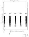
- FIG. 2 is a diagramatic illustration of the division of the overall format of a printing plate on the printing-plate carrier into subareas.
- the particular advantage of the method according to the present invention resides in the fact that the intended quality assurance of the edition printing is consequently cost-effective and flexible and, in particular, can be adapted to different printing set-ups ( FIG. 1 a , P—P of two cylinders, for example a printing-plate cylinder 1 and a blanket cylinder 2 ) and the associated cylinder deflections, without making constructional measures necessary.
- FIG. 1 b shows the consequences of the undesired positional change (deflection) of the two cylinders 1 and 2 of FIG. 1 a in relation to each other during printing operation.
- the transfer pressure P—P becomes non-uniform over the cylinder width, that is to say a line pressure which is irregular over the cylinder width is produced.
- position 1 shows approximately the middle of the cylinder width
- position 3 shows the left-hand edge region
- position 3 ′ shows the right-hand edge region of the cylinder
- positions 2 and 2 ′ show a subarea of the cylinder (printing-plate carrier) 1 or 2 arranged between middle and edge.
- the printing-plate carrier be repeatedly subdivided by computation in terms of its width and axial length, for each subarea an actual transfer characteristic curve be determined in each case, each actual transfer characteristic curve be compared by computation with the predetermined desired printing characteristic curve, the deviations of the actual characteristic curves from the desired characteristic curve based on each circumferential subarea of the printing-plate carrier be used to compensate the deviations in the form of a computational correction of the machine-specific
- FIG. 2 demonstrates the division of a printing-plate width 3 for example into five subareas (zones) Pos 1 , 2 , 2 ′, 3 , 3 ′ which, for the purpose of illustration, correspond to the subareas Pos 1 , 2 , 2 ′, 3 , 3 ′ of FIG. 1 b.
- the subareas of the printing-plate carrier are defined as zones Pos 1 , 2 , 2 ′, 3 , 3 ′ in a manner analogous to the inking zones in offset printing and, for each zone, the corresponding actual transfer characteristic curve Pos 1 , 2 , 3 ( FIG. 1 c ) is determined by measurement with the aid of test prints.
- the zones are, for example, 30 mm wide.
- the determination by measurement of the actual transfer characteristic curve of each zone is then carried out with the aid of stepped half-tone wedges 4 , which are printed so as to be associated with each zone in the circumferential direction (see FIG. 2 ).
- the determination of a printing characteristic curve for example in the form of “print area coverage as a function of the area coverage of the printing plate at a given full-tone density”, is a standard method in the graphical industry.
- the desired printing characteristic curve can, for example, be predetermined by standardizing the offset print in accordance with ISO 12647.
- the machine-specific image data converted in the RIP are supplied as an intermediate format to a bitmap memory, and the deviations of the actual transfer characteristic curves from the desired printing characteristic curve corresponding to each subarea for the computational correction of the machine-specific image data into a final format are supplied to the bitmap memory.
- the image data are converted into a Contone (CT)/linework (LW) format, taking account of the desired printing characteristic curve as is known in the prior art.
- CT/LW format such as has been used for many years in the field, for example, and is still used nowadays or has also been referred to as a delta list, offers for each color separation at least one bitmap having, for example, 300 dpi with a color depth of at least 8 bits per pixel, into which all the image elements describing grey values enter (Contone data), and one or more highly resolved binary bitmaps, for example with 2400 dpi (Linework data), which contain graphic elements, text elements and-mask information.
- CT Contone
- bitmap intermediate memory
- CT/LW format final format
- a basic characteristic curve in the form of an actual transfer characteristic curve belonging to a preferred subarea of the printing-plate carrier is defined as the predetermined desired printing characteristic curve, that is to say a single basic characteristic curve for each printing point at which the method according to the invention is applied, and for each subarea or zone, a correction is calculated on the basis of this basic characteristic curve.
- the basic characteristic curve can be, for example, the actual transfer characteristic curve of the subarea or zone lying in the middle of the printing-plate carrier or that of the subarea or of the zone between the middle and edge of the printing-plate carrier, preferably spaced about 1 ⁇ 4 of the axial length of the printing-plate carrier from its edge.
- the image data are again converted into a CT/LW format, preferably of the size of the printing plate, while taking account of the basic characteristic curve.
- the following correction of the image data is here composed of the known correction of the data for printing-plate production, which for example takes into account the dot broadening as a result of the imagesetting operation, and likewise the correction of the deviations of the actual tonal value gains in the print from the desired tonal value gain.
- a dedicated basic characteristic curve is likewise applied to each different printing point. These basic characteristic curves may be slightly different.
- the respectively determined correction values are then applied, subarea by subarea or zone by zone, to the CT data, so that slightly changed values in the bitmap are produced.
- the raster is then generated from the CT/LW format and the printing plate is created.
- all the actual transfer characteristic curves are determined by computation instead of by measurement.
- the deflection of the cylindrical printing-plate carrier is determined, for example, by measuring the changed imprint width under deflection. This deflection results in a change in the transfer pressure, as described at the beginning.
- the deflection of the printing-plate carrier can be determined on the basis of theoretical calculations using known material parameters and surface and line forces, for example by means of finite element calculation.
- a starting correction can be predetermined directly at the factory and without the necessity for test prints and measurements on site.
- a method in which subdividing the printing-plate carrier by computation is performed without steps, so that, from the first to the last subarea, the actual transfer characteristic curve can be interpolated linearly or polynomially.
- the calculated correction of the machine-specific image data is performed during the conversion of the machine-independent image data in the RIP.
- the correction of the image data can be performed on an object basis in a step carried out before rastering. This can be done, for example, on a printing-plate-related display list. There, individual objects, bitmap or vector objects are then subjected to a conversion, corresponding to their position on the printing plate.
- correction measures of the method according to the invention can be the same for the entire printing press, that is to say for every printing point with similar geometric and printing conditions. However, they can also vary from printing point to printing point and, for each printing point, can be determined individually, stored and applied to the data prepared for that printing point.
- a self-teaching method the two can be combined, such as already disclosed in self-teaching systems for optimizing the inking zone presetting in rotary printing presses, for example, U.S. Pat. No 6,230,622 which is hereby incorporated by reference in its entirety.
- an initial correction is predetermined, which results on the basis of experience with already existing machines and theoretical considerations.
- measurements are then made in the prints produced and, as a result, the correction is improved. This can be done individually for each printing point.
- the measurements can be carried out by means of handheld measuring instruments or automated measuring devices, separately or within the context of measurements used, for example, for the inking zone presetting.
- the corrections could be performed on the basis of the printing paper used or the paper/ink combination used, for example in a classification of the paper classes in accordance with ISO 12647. It would then be necessary to use the respectively associated correction for each paper class used in order to generate the printing plate.
Landscapes
- Engineering & Computer Science (AREA)
- Multimedia (AREA)
- Signal Processing (AREA)
- Mechanical Engineering (AREA)
- Manufacturing & Machinery (AREA)
- Manufacture Or Reproduction Of Printing Formes (AREA)
- Inking, Control Or Cleaning Of Printing Machines (AREA)
- Facsimile Image Signal Circuits (AREA)
- Printing Methods (AREA)
Abstract
Description
Claims (11)
Applications Claiming Priority (2)
| Application Number | Priority Date | Filing Date | Title |
|---|---|---|---|
| DE10213708.0 | 2002-03-27 | ||
| DE10213708A DE10213708A1 (en) | 2002-03-27 | 2002-03-27 | Print forme production method, especially for a rotary lithographic offset printer, whereby corrections for print cylinder deformation are applied by determination of correction values from differences in transfer curves |
Publications (2)
| Publication Number | Publication Date |
|---|---|
| US20040100659A1 US20040100659A1 (en) | 2004-05-27 |
| US7224490B2 true US7224490B2 (en) | 2007-05-29 |
Family
ID=28050899
Family Applications (1)
| Application Number | Title | Priority Date | Filing Date |
|---|---|---|---|
| US10/401,254 Expired - Fee Related US7224490B2 (en) | 2002-03-27 | 2003-03-27 | Method of producing a printing plate on a cylindrical printing-plate carrier in a rotary printing press |
Country Status (6)
| Country | Link |
|---|---|
| US (1) | US7224490B2 (en) |
| JP (1) | JP4197978B2 (en) |
| CN (1) | CN100335274C (en) |
| CA (1) | CA2423724A1 (en) |
| CH (1) | CH696142A5 (en) |
| DE (1) | DE10213708A1 (en) |
Cited By (1)
| Publication number | Priority date | Publication date | Assignee | Title |
|---|---|---|---|---|
| US20080266586A1 (en) * | 2006-10-26 | 2008-10-30 | Jurgen Rautert | Method and System for Producing Printing Forms for Anilox Printing Presses |
Families Citing this family (3)
| Publication number | Priority date | Publication date | Assignee | Title |
|---|---|---|---|---|
| DE102007009091A1 (en) * | 2007-02-24 | 2008-08-28 | Man Roland Druckmaschinen Ag | System for imaging of printing forms |
| DE102008033403B4 (en) * | 2008-07-16 | 2012-02-16 | Manroland Ag | Method for imaging printed image carriers |
| ITBO20130568A1 (en) * | 2013-10-16 | 2015-04-17 | Bieffebi Spa | MODULE, PROCEDURE AND EQUIPMENT FOR THE DIMENSIONAL ANALYSIS OF A CLICHE-DOOR CYLINDER |
Citations (4)
| Publication number | Priority date | Publication date | Assignee | Title |
|---|---|---|---|---|
| US5500801A (en) | 1993-10-16 | 1996-03-19 | Heidelberger Druckmaschinen Ag | Device for compensating for deviations in register in printed products |
| US5602970A (en) | 1991-03-21 | 1997-02-11 | Maschinenfabrik Wifag | Process for setting the halftone dot sizes for a rotary offset printing machine |
| US6213019B1 (en) * | 1998-10-06 | 2001-04-10 | Man Roland Druckmaschinen Ag | Method and apparatus for ink feed control |
| US20020043172A1 (en) | 2000-08-31 | 2002-04-18 | Axel Hauck | Method of correcting local, machine-based inking errors in rotary printing machines |
Family Cites Families (3)
| Publication number | Priority date | Publication date | Assignee | Title |
|---|---|---|---|---|
| DE4328026A1 (en) * | 1993-08-20 | 1995-03-09 | Roland Man Druckmasch | Communication method and system for computer-aided printing |
| DE19844495B4 (en) * | 1998-09-29 | 2005-04-07 | Man Roland Druckmaschinen Ag | Method for color calibration by means of color management for a digitally controllable printing press with a rewritable printing form |
| JP2001086359A (en) * | 1999-09-16 | 2001-03-30 | Mitsubishi Heavy Ind Ltd | Multicolor plate making printing system |
-
2002
- 2002-03-27 DE DE10213708A patent/DE10213708A1/en not_active Withdrawn
-
2003
- 2003-02-05 CH CH00167/03A patent/CH696142A5/en not_active IP Right Cessation
- 2003-03-27 CN CNB031083048A patent/CN100335274C/en not_active Expired - Fee Related
- 2003-03-27 CA CA002423724A patent/CA2423724A1/en not_active Abandoned
- 2003-03-27 US US10/401,254 patent/US7224490B2/en not_active Expired - Fee Related
- 2003-03-27 JP JP2003088918A patent/JP4197978B2/en not_active Expired - Fee Related
Patent Citations (4)
| Publication number | Priority date | Publication date | Assignee | Title |
|---|---|---|---|---|
| US5602970A (en) | 1991-03-21 | 1997-02-11 | Maschinenfabrik Wifag | Process for setting the halftone dot sizes for a rotary offset printing machine |
| US5500801A (en) | 1993-10-16 | 1996-03-19 | Heidelberger Druckmaschinen Ag | Device for compensating for deviations in register in printed products |
| US6213019B1 (en) * | 1998-10-06 | 2001-04-10 | Man Roland Druckmaschinen Ag | Method and apparatus for ink feed control |
| US20020043172A1 (en) | 2000-08-31 | 2002-04-18 | Axel Hauck | Method of correcting local, machine-based inking errors in rotary printing machines |
Cited By (2)
| Publication number | Priority date | Publication date | Assignee | Title |
|---|---|---|---|---|
| US20080266586A1 (en) * | 2006-10-26 | 2008-10-30 | Jurgen Rautert | Method and System for Producing Printing Forms for Anilox Printing Presses |
| US8358434B2 (en) | 2006-10-26 | 2013-01-22 | Heidelberger Druckmaschinen Ag | Method and system for producing printing forms for anilox printing presses |
Also Published As
| Publication number | Publication date |
|---|---|
| JP4197978B2 (en) | 2008-12-17 |
| CN100335274C (en) | 2007-09-05 |
| US20040100659A1 (en) | 2004-05-27 |
| CN1446688A (en) | 2003-10-08 |
| CH696142A5 (en) | 2007-01-15 |
| JP2003326664A (en) | 2003-11-19 |
| CA2423724A1 (en) | 2003-09-27 |
| DE10213708A1 (en) | 2003-10-23 |
Similar Documents
| Publication | Publication Date | Title |
|---|---|---|
| US6580524B1 (en) | Method for profiling and calibrating a digitally controllable printing machine having a permanent printing plate | |
| US5662044A (en) | Offset printing method | |
| US6917448B2 (en) | Dot gain calibration method and apparatus | |
| US9221288B2 (en) | Printing process and system for ascertaining register defects | |
| US20040200369A1 (en) | Method and system for printing press image distortion compensation | |
| JP5336721B2 (en) | Plate making for anilox press | |
| US6975430B1 (en) | Method and apparatus for adjusting ink supply amount for printing press | |
| US7224490B2 (en) | Method of producing a printing plate on a cylindrical printing-plate carrier in a rotary printing press | |
| US6701847B2 (en) | Method of varying the ink density of the full tone in offset printing within a rotary printing machine | |
| US8300275B2 (en) | Method for reducing the area coverage of a printing plate | |
| US6684790B2 (en) | Method of determining the area coverage of printing plates | |
| EP2979866B1 (en) | Platemaking method, platemaking device, and printing press | |
| US6893105B2 (en) | Method for printing an image from a halftone binary bitmap using multiple exposures | |
| US8368963B2 (en) | Method for exposing a printing form and corresponding computer program product | |
| DE60014249T2 (en) | Apparatus and method for image data processing and textile printing machine, which includes such image data processing apparatus | |
| US11554592B2 (en) | Method of printing at least two print jobs on one printing machine | |
| US20060238817A1 (en) | Method and system for printing management | |
| JP2001086359A (en) | Multicolor plate making printing system | |
| JP2005231256A (en) | Method and equipment for printed image quality control of color printer | |
| HK1115099A (en) | Method and system for producing printing forms for anilox printing presses |
Legal Events
| Date | Code | Title | Description |
|---|---|---|---|
| AS | Assignment |
Owner name: MAN ROLAND DRUCKMASCHINEN AG, GERMANY Free format text: ASSIGNMENT OF ASSIGNORS INTEREST;ASSIGNORS:SCHNEIDER, JOSEF;WEICHMANN, ARMIN;REEL/FRAME:013917/0206;SIGNING DATES FROM 20030314 TO 20030318 |
|
| FEPP | Fee payment procedure |
Free format text: PAYOR NUMBER ASSIGNED (ORIGINAL EVENT CODE: ASPN); ENTITY STATUS OF PATENT OWNER: LARGE ENTITY |
|
| AS | Assignment |
Owner name: MANROLAND AG, GERMANY Free format text: CHANGE OF NAME;ASSIGNOR:MAN ROLAND DRUCKMASCHINEN AG;REEL/FRAME:022024/0567 Effective date: 20080115 Owner name: MANROLAND AG,GERMANY Free format text: CHANGE OF NAME;ASSIGNOR:MAN ROLAND DRUCKMASCHINEN AG;REEL/FRAME:022024/0567 Effective date: 20080115 |
|
| FPAY | Fee payment |
Year of fee payment: 4 |
|
| REMI | Maintenance fee reminder mailed | ||
| LAPS | Lapse for failure to pay maintenance fees | ||
| STCH | Information on status: patent discontinuation |
Free format text: PATENT EXPIRED DUE TO NONPAYMENT OF MAINTENANCE FEES UNDER 37 CFR 1.362 |
|
| STCH | Information on status: patent discontinuation |
Free format text: PATENT EXPIRED DUE TO NONPAYMENT OF MAINTENANCE FEES UNDER 37 CFR 1.362 |
|
| FP | Lapsed due to failure to pay maintenance fee |
Effective date: 20150529 |