US7222444B2 - Coordinated linkage system for a work vehicle - Google Patents
Coordinated linkage system for a work vehicle Download PDFInfo
- Publication number
- US7222444B2 US7222444B2 US10/970,622 US97062204A US7222444B2 US 7222444 B2 US7222444 B2 US 7222444B2 US 97062204 A US97062204 A US 97062204A US 7222444 B2 US7222444 B2 US 7222444B2
- Authority
- US
- United States
- Prior art keywords
- tool
- boom
- signal
- dipperstick
- actuator
- Prior art date
- Legal status (The legal status is an assumption and is not a legal conclusion. Google has not performed a legal analysis and makes no representation as to the accuracy of the status listed.)
- Expired - Lifetime
Links
- 238000004891 communication Methods 0.000 claims description 14
- 238000000034 method Methods 0.000 claims description 5
- 239000000463 material Substances 0.000 description 8
- 230000005484 gravity Effects 0.000 description 6
- 230000004044 response Effects 0.000 description 5
- 239000012530 fluid Substances 0.000 description 4
- 238000010586 diagram Methods 0.000 description 3
- 230000000694 effects Effects 0.000 description 3
- 230000002028 premature Effects 0.000 description 3
- 238000009412 basement excavation Methods 0.000 description 2
- 238000005516 engineering process Methods 0.000 description 2
- 230000007246 mechanism Effects 0.000 description 1
- 238000012986 modification Methods 0.000 description 1
- 230000004048 modification Effects 0.000 description 1
- 230000008569 process Effects 0.000 description 1
Images


Classifications
-
- E—FIXED CONSTRUCTIONS
- E02—HYDRAULIC ENGINEERING; FOUNDATIONS; SOIL SHIFTING
- E02F—DREDGING; SOIL-SHIFTING
- E02F3/00—Dredgers; Soil-shifting machines
- E02F3/04—Dredgers; Soil-shifting machines mechanically-driven
- E02F3/28—Dredgers; Soil-shifting machines mechanically-driven with digging tools mounted on a dipper- or bucket-arm, i.e. there is either one arm or a pair of arms, e.g. dippers, buckets
- E02F3/36—Component parts
- E02F3/42—Drives for dippers, buckets, dipper-arms or bucket-arms
- E02F3/43—Control of dipper or bucket position; Control of sequence of drive operations
- E02F3/435—Control of dipper or bucket position; Control of sequence of drive operations for dipper-arms, backhoes or the like
- E02F3/436—Control of dipper or bucket position; Control of sequence of drive operations for dipper-arms, backhoes or the like for keeping the dipper in the horizontal position, e.g. self-levelling
-
- E—FIXED CONSTRUCTIONS
- E02—HYDRAULIC ENGINEERING; FOUNDATIONS; SOIL SHIFTING
- E02F—DREDGING; SOIL-SHIFTING
- E02F3/00—Dredgers; Soil-shifting machines
- E02F3/04—Dredgers; Soil-shifting machines mechanically-driven
- E02F3/28—Dredgers; Soil-shifting machines mechanically-driven with digging tools mounted on a dipper- or bucket-arm, i.e. there is either one arm or a pair of arms, e.g. dippers, buckets
- E02F3/36—Component parts
- E02F3/42—Drives for dippers, buckets, dipper-arms or bucket-arms
- E02F3/43—Control of dipper or bucket position; Control of sequence of drive operations
- E02F3/431—Control of dipper or bucket position; Control of sequence of drive operations for bucket-arms, front-end loaders, dumpers or the like
- E02F3/432—Control of dipper or bucket position; Control of sequence of drive operations for bucket-arms, front-end loaders, dumpers or the like for keeping the bucket in a predetermined position or attitude
-
- E—FIXED CONSTRUCTIONS
- E02—HYDRAULIC ENGINEERING; FOUNDATIONS; SOIL SHIFTING
- E02F—DREDGING; SOIL-SHIFTING
- E02F3/00—Dredgers; Soil-shifting machines
- E02F3/04—Dredgers; Soil-shifting machines mechanically-driven
- E02F3/96—Dredgers; Soil-shifting machines mechanically-driven with arrangements for alternate or simultaneous use of different digging elements
- E02F3/963—Arrangements on backhoes for alternate use of different tools
- E02F3/964—Arrangements on backhoes for alternate use of different tools of several tools mounted on one machine
Definitions
- the invention relates to a system for sensing and automatically controlling the orientation of a work tool with respect to the earth.
- a variety of work machines can be equipped with tools for performing a work function. Examples of such machines include a wide variety of loaders, excavators, tele-handlers, and aerial lifts.
- a work vehicle such as backhoe loader may be equipped with a first tool, such as a backhoe bucket or other structure, for excavating and material handling functions.
- a swing frame pivotally attaches to the vehicle frame at a rear portion of the vehicle, a backhoe boom pivotally attaches to the swing frame, a dipperstick pivotally attaches to the backhoe boom, and the work tool pivotally attaches to the dipperstick about a backhoe bucket pivot.
- a vehicle operator controls the orientation of the first tool relative to the dipperstick by a first tool actuator. The operator also controls the rotational position of the boom relative to the vehicle frame, and the dipperstick relative to the boom, by corresponding actuators.
- the aforementioned actuators are typically comprised of one or more double acting hydraulic cylinders and
- a loader boom is pivotally attached to the vehicle frame at a front portion of the backhoe loader and a second tool, such as a loader bucket, is pivotally attached to the loader boom at a loader bucket pivot.
- Work operation with a loader bucket entails similar problems to those encountered in work operations with the backhoe bucket.
- the invention makes use of a tilt sensor that, when attached to an object, such as the tool, detects the object's inclination with respect to the earth.
- the inclination of the tool is detected independently of the vehicle frame orientation and independently of the initial orientation of the tool. The result is a simpler control system and improved tool orientation control relative to gravity.
- tilt sensor utilized in the invention makes use of a new micro-electromechanical structures (MEMS) technology and is commercially available from Crossbow International, Inc.
- MEMS micro-electromechanical structures
- Crossbow International, Inc A number of other tilt sensors, including those utilizing capacitive technology, would be suitable for use in the invention and are also commercially available.
- An object of the present invention is to provide an improved system for sensing and automatically controlling the orientation of a tool for a work vehicle.
- the system automatically controls tool orientation by making use of a tilt sensor attached to the tool to detect an angle of the tool with respect to the earth.
- a controller maintains the tool at a selected angle.
- the illustrated invention comprises a backhoe loader which includes a backhoe assembly, and a loader assembly.
- the backhoe assembly includes a swing frame pivotally attached to the frame of the backhoe loader, a backhoe boom pivotally attached to the swing frame, a backhoe boom actuator for controllably pivoting the boom relative to the swing frame, a dipperstick pivotally attached to the boom, a dipperstick actuator for controllably pivoting the dipperstick relative to the boom, a backhoe tool pivotally attached to the dipperstick, a backhoe tool actuator for controllably moving the backhoe tool about its pivot, and the aforementioned tilt sensor.
- the swing frame, the backhoe boom and the dipperstick shall be referenced herein as the backhoe linkage.
- a controller processes data from the tilt sensor and commands movement of the tool actuator in response thereto.
- the illustrated embodiment of the backhoe also includes a backhoe tool command input device to effect operation of the backhoe tool actuator, and a tool auto-hold command input device to enable a tool auto-hold function for maintaining the tool in a set orientation.
- the loader includes a loader boom pivotally attached to the vehicle frame, a loader boom actuator for controllably pivoting the loader boom relative to the vehicle frame, a loader tool pivotally attached to the loader boom, and a loader tool actuator for controllably pivoting the loader tool relative to the loader boom.
- the loader also includes a loader tool command device to effect operation of the loader tool actuator and a loader tool auto-hold command input device to enable a loader tool auto-hold function for maintaining the loader tool in a set orientation.
- the controller When an tool auto-hold function is enabled, the controller maintains a tool orientation by commanding the tool actuator to move the tool such that the detected angle, i.e., the output voltage of the tilt sensor remains about the same.
- the controller is adapted to discontinue the tool auto-hold function when the operator manipulates the tool command input device to effect tool movement.
- the controller resumes tool auto-hold function once the operator discontinues manipulation of the tool command input device, reestablishing the initial tool orientation at the new orientation affected by the operator. Additionally, the operator may manipulate an auto-hold command input device to selectively enable and disable the tool auto-hold function.
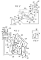
- FIG. 1 is a side view of a backhoe loader.
- FIG. 2 is a schematic diagram of a loader bucket orientation sensing and automatic control system.
- FIG. 3 is a schematic diagram of a backhoe bucket orientation sensing and automatic control system.
- FIG. 4 is a schematic diagram showing a frame tilt sensor in communication with a controller.
- FIG. 1 illustrates a self-propelled work vehicle, such as a backhoe loader 10 .
- the backhoe loader 10 has a frame 12 , to which are attached ground engaging wheels 14 and 15 for supporting and propelling the vehicle 10 .
- Attached to the front of the vehicle is a loader assembly 16
- Attached to the rear of the vehicle is a backhoe assembly 18 .
- Both the loader assembly 16 and backhoe assembly 18 each perform a variety of excavating and material handling functions.
- An operator controls the functions of the vehicle 10 from an operator's station 20 .
- the loader assembly 16 comprises a loader boom 22 and a tool such as a loader bucket or other structure 24 .
- the loader boom 22 has a first end 26 pivotally attached to the frame 12 about a horizontal loader boom pivot 28 , and a second end 30 to which the loader bucket 24 pivotally attaches about a horizontal loader bucket pivot 32 .
- a loader boom actuator having a loader boom hydraulic cylinder 36 extending between the vehicle frame 12 and the loader boom 22 , controllably moves the loader boom 22 about the loader boom pivot 28 .
- a loader bucket actuator 38 having a loader bucket hydraulic cylinder 40 extending between the loader boom 22 and the loader bucket 24 , controllably moves the loader bucket 24 about the loader bucket pivot 32 .
- the loader bucket actuator 38 comprises a loader bucket electro-hydraulic circuit 42 hydraulically coupled to the loader bucket hydraulic cylinder 40 .
- the loader bucket electro-hydraulic circuit 42 supplies and controls the flow of hydraulic fluid to the loader bucket hydraulic cylinder 40 .
- the operator commands movement of the loader assembly 16 by manipulating a loader bucket command input device 44 and a loader boom command input device 46 .
- the loader bucket command input device 44 is adapted to generate a loader bucket command signal 48 in response to manipulation by the operator, proportional to a desired loader bucket movement.
- a controller 50 in communication with the loader bucket command input device 44 and loader bucket actuator 38 , receives the loader bucket command signal 48 and responds by generating a loader bucket control signal 52 , which is received by the loader bucket electro-hydraulic circuit 42 .
- the loader bucket electro-hydraulic circuit 42 responds to the loader bucket control signal 52 by directing hydraulic fluid to the loader bucket hydraulic cylinder 40 , causing the hydraulic cylinder 40 to move the loader bucket 24 accordingly.
- FIG. 2 illustrates an improved actuator control system adapted to automatically maintain an initial or a set loader bucket orientation or tilt angle with respect to the earth.
- the present invention makes use of a loader bucket tilt angle sensor 54 attached to the loader bucket 24 , in communication with the controller 50 .
- the loader bucket tilt angle sensor 54 is adapted to sense an angle of the bucket relative to the earth and to generate a corresponding loader bucket angle signal 56 .
- the controller 50 is adapted to receive the loader bucket angle signal 56 and to generate a loader bucket control signal 52 in response, causing the loader bucket actuator 38 to move the loader bucket 24 to achieve a desired loader bucket angle.
- the object of the invention is an auto-hold function to maintain the initial loader bucket angle set by the operator, relative to gravity
- the desired loader bucket angle is maintained.
- the controller 50 is adapted to suspend the auto-hold function when the operator commands movement of the loader bucket 24 , i.e., upon receiving the loader bucket command signal 48 , and reestablishing the initial loader bucket orientation as the orientation of the loader bucket 24 immediately after the loader bucket command signal 48 terminates.
- the present invention also utilizes a loader auto-hold command switch 58 in communication with the controller 50 .
- the loader auto-hold command switch 58 is adapted to generate a loader auto-hold command signal 60 corresponding to a manipulation of the loader auto-hold command switch 58 by the operator to enable operation of the auto-hold function for the loader bucket 24 .
- the controller 50 is adapted to ignore the loader bucket angle signal 56 until the controller 50 receives the loader auto-hold command signal 60 from the loader auto-hold command switch 58 .
- a loader boom tilt angle sensor 57 for detecting the angle of the loader boom 22 relative to the earth and automatically generating loader boom angle signals, is attached to the loader boom 22 .
- the controller 50 is also capable of receiving the loader boom angle signals generated by the boom tilt angle sensor 57 and automatically generating the loader bucket control signals based on the loader boom angle signals.
- the backhoe assembly 18 comprises a swing frame 62 , a backhoe boom 64 , a dipperstick 66 , and a backhoe tool such as a backhoe bucket or other structure 68 .
- the swing frame 62 has a first swing frame end 70 pivotally attached to the frame 12 about a vertical pivot 72 , and a second swing frame end 74 .
- the backhoe boom 64 has a first backhoe boom end 76 pivotally attached to the second swing frame end 74 about a horizontal backhoe boom pivot 78 , and a second backhoe boom end 80 .
- the dipperstick 66 has a first dipperstick end 82 pivotally attached to the second backhoe boom end 80 about a horizontal dipperstick pivot 84 , and a second end 86 to which the backhoe bucket 68 pivotally attaches via a backhoe bucket pivot 88 .
- a swing frame actuator including a swing frame hydraulic cylinder 90 extending between the vehicle frame 12 and the swing frame 62 , controllably moves the swing frame 62 about the vertical pivot 72 .
- a backhoe boom actuator including a backhoe boom hydraulic cylinder 92 extending between the swing frame 62 and the backhoe boom 64 , controllably moves the backhoe boom 64 about the backhoe boom pivot 78 .
- a dipperstick actuator including a dipperstick hydraulic cylinder 94 extending between the backhoe boom 64 and the dipperstick 66 , controllably moves the dipperstick 66 about the dipperstick pivot 84 .
- a backhoe bucket actuator 96 including a backhoe bucket hydraulic cylinder 98 extending between the dipperstick 66 and the backhoe bucket 68 , controllably moves the backhoe bucket 68 about the backhoe bucket pivot 88 .
- the backhoe bucket actuator 96 comprises a backhoe bucket electro-hydraulic circuit 100 , in connection the backhoe bucket hydraulic cylinder 98 , which supplies and controls the flow of hydraulic fluid to the backhoe bucket hydraulic cylinder 98 .
- the operator commands movement of the backhoe assembly 18 by manipulating a backhoe bucket command input device 102 , a dipperstick command input device 104 , a backhoe boom command input device 106 , and a swing frame command input device.
- the backhoe bucket command input device 102 is adapted to generate a backhoe bucket command signal 108 in response to manipulation by the operator, proportional to a desired backhoe bucket movement.
- the controller 50 in communication with the backhoe bucket command input device 102 , dipperstick command input device 104 , backhoe boom command input device 106 , and the backhoe bucket actuator 96 , receives the backhoe bucket command signal 108 and responds by generating a backhoe bucket control signal 110 , which is received by the backhoe bucket electro-hydraulic circuit 100 .
- the backhoe bucket electro-hydraulic circuit 100 responds to the backhoe bucket control signal 110 by directing hydraulic fluid to the backhoe bucket hydraulic cylinder 98 , causing the hydraulic cylinder 98 to move the backhoe bucket 68 accordingly.
- the backhoe bucket 68 During a work operation with the backhoe bucket 68 , such as lifting or excavating material, it is, at times, desirable to maintain an initial backhoe bucket orientation relative to the earth to prevent premature dumping of material or to obtain a constant excavation shear angle.
- the operator To maintain the initial backhoe bucket orientation relative to gravity, the operator is required to continually manipulate the backhoe bucket command input device 102 to adjust the backhoe bucket orientation as the backhoe boom 64 and dipperstick 66 are moved during the work operation.
- FIG. 3 illustrates an improved actuator control system adapted to automatically maintain an initial, or a set, backhoe bucket orientation, or angle.
- the invention makes use of a backhoe bucket tilt angle sensor 112 attached to the backhoe bucket 68 , in communication with the controller 50 .
- the backhoe bucket tilt angle sensor 112 is adapted to sense a backhoe bucket tilt angle relative to the earth and to generate a corresponding backhoe bucket angle signal 114 .
- the controller 50 is adapted to receive the backhoe bucket signal 114 and to generate a backhoe bucket control signal 110 in response, causing the backhoe bucket actuator 96 to move the backhoe bucket 68 to achieve an angle with respect to the earth.
- the object of the invention is an auto-hold function to maintain the initial backhoe bucket orientation set by the operator, relative to the earth
- the set backhoe bucket angle is maintained.
- the controller 50 is adapted suspend the auto-hold function while the operator commands movement of the backhoe bucket 68 when receiving the backhoe bucket command signal 108 , and reestablishing the initial backhoe bucket orientation as the set orientation of the backhoe bucket 68 immediately after the backhoe bucket command signal 108 terminates.
- the invention also utilizes a backhoe auto-hold command switch 116 in communication with the controller 50 .
- the backhoe auto-hold command switch 116 is adapted to generate a backhoe auto-hold command signal 118 corresponding to a manipulation of the backhoe auto-hold command switch 116 by the operator to enable operation of the auto-hold function for the backhoe bucket 68 .
- the controller 50 is adapted to ignore the backhoe bucket angle signal 114 until the controller 50 receives the backhoe auto-hold command signal 118 from the backhoe auto-hold command switch 116 .
- the controller 50 may be adapted to ignore the backhoe bucket angle signal 114 unless receiving a backhoe boom command signal 122 from the backhoe boom command input device 106 , or a dipperstick command signal 120 from the dipperstick command input device 104 .
- a backhoe boom tilt angle sensor 63 is attached to the backhoe boom 66 and a dipperstick tilt angle sensor 67 is attached to the dipperstick 64 .
- the controller 50 is also capable of receiving backhoe boom angle signals and dipperstick angle signals relative to the earth generated by the boom tilt angle sensor and the dipperstick tilt angle sensor, respectively and automatically generating backhoe bucket control signals based on at least one of the backhoe boom angle signals an the diperstick angle signals.
- FIG. 4 illustrates a frame tilt sensor 73 attached to the frame 12 .
- the frame tilt sensor 73 detects an inclination of the frame 12 with respect to the earth and generates a corresponding frame inclination signal 75 .
- the controller 50 is capable of automatically generating a tool control signal based on the frame inclination signal, the boom inclination signal, the dipperstick inclination signal and the tool inclination signal.
Landscapes
- Engineering & Computer Science (AREA)
- Mechanical Engineering (AREA)
- Mining & Mineral Resources (AREA)
- Civil Engineering (AREA)
- General Engineering & Computer Science (AREA)
- Structural Engineering (AREA)
- Operation Control Of Excavators (AREA)
- Forklifts And Lifting Vehicles (AREA)
Abstract
Description
Claims (22)
Priority Applications (3)
| Application Number | Priority Date | Filing Date | Title |
|---|---|---|---|
| US10/970,622 US7222444B2 (en) | 2004-10-21 | 2004-10-21 | Coordinated linkage system for a work vehicle |
| EP05109479A EP1650358A3 (en) | 2004-10-21 | 2005-10-12 | Control system for coordinated control of a boom of a working vehicle |
| JP2005306560A JP4989874B2 (en) | 2004-10-21 | 2005-10-21 | Linkage mechanism system for work vehicles |
Applications Claiming Priority (1)
| Application Number | Priority Date | Filing Date | Title |
|---|---|---|---|
| US10/970,622 US7222444B2 (en) | 2004-10-21 | 2004-10-21 | Coordinated linkage system for a work vehicle |
Publications (2)
| Publication Number | Publication Date |
|---|---|
| US20060096137A1 US20060096137A1 (en) | 2006-05-11 |
| US7222444B2 true US7222444B2 (en) | 2007-05-29 |
Family
ID=35519670
Family Applications (1)
| Application Number | Title | Priority Date | Filing Date |
|---|---|---|---|
| US10/970,622 Expired - Lifetime US7222444B2 (en) | 2004-10-21 | 2004-10-21 | Coordinated linkage system for a work vehicle |
Country Status (3)
| Country | Link |
|---|---|
| US (1) | US7222444B2 (en) |
| EP (1) | EP1650358A3 (en) |
| JP (1) | JP4989874B2 (en) |
Cited By (15)
| Publication number | Priority date | Publication date | Assignee | Title |
|---|---|---|---|---|
| US20080041805A1 (en) * | 2006-08-16 | 2008-02-21 | Jarkko Jantti | Control Of A Boom Construction And A Tool Articulated Thereto |
| US20080313935A1 (en) * | 2007-06-22 | 2008-12-25 | Boris Trifunovic | Electronic Parallel Lift And Return To Carry On A Backhoe Loader |
| US20090088931A1 (en) * | 2007-09-28 | 2009-04-02 | Caterpillar Inc. | Linkage control system with position estimator backup |
| US20090159302A1 (en) * | 2007-12-19 | 2009-06-25 | Caterpillar Inc. | Constant work tool angle control |
| US20090198382A1 (en) * | 2008-01-31 | 2009-08-06 | Caterpillar Inc. | Tool control system |
| US20100161185A1 (en) * | 2008-12-23 | 2010-06-24 | Caterpillar Inc. | Method and apparatus for calculating payload weight |
| US20110190942A1 (en) * | 2009-12-18 | 2011-08-04 | Caterpillar Inc. | Lift arm and implement control system |
| US20140261152A1 (en) * | 2011-10-17 | 2014-09-18 | Hitachi Construction Machinery Co., Ltd. | System for Indicating Parking Position and Direction of Dump Truck and Hauling System |
| US8862340B2 (en) | 2012-12-20 | 2014-10-14 | Caterpillar Forest Products, Inc. | Linkage end effecter tracking mechanism for slopes |
| US20140366407A1 (en) * | 2011-09-30 | 2014-12-18 | Meccanica Breganzese S.P.A. In Breve Mb S.P.A. | Bucket for screening and crushing inert material having a balancing valve |
| US20150275469A1 (en) * | 2014-03-28 | 2015-10-01 | Caterpillar Inc. | Lift Arm and Coupler Control System |
| US10030354B1 (en) * | 2017-02-28 | 2018-07-24 | CNH Industrial America, LLC | Anti-spill for loaders |
| US20180230672A1 (en) * | 2016-11-29 | 2018-08-16 | Komatsu Ltd. | Control device for construction machine and method of controlling construction machine |
| US10865542B2 (en) | 2018-01-25 | 2020-12-15 | Caterpillar Inc. | Grading control system using machine linkages |
| US20210404142A1 (en) * | 2020-06-30 | 2021-12-30 | Deere & Company | Implement control system for machine |
Families Citing this family (11)
| Publication number | Priority date | Publication date | Assignee | Title |
|---|---|---|---|---|
| US7810260B2 (en) * | 2007-12-21 | 2010-10-12 | Caterpillar Trimble Control Technologies Llc | Control system for tool coupling |
| ITBO20090189A1 (en) * | 2009-03-26 | 2010-09-27 | Cast Group S R L | EARTH MOVING MACHINE |
| JP5037561B2 (en) * | 2009-05-13 | 2012-09-26 | 株式会社小松製作所 | Work vehicle |
| GB2489663B (en) * | 2011-03-21 | 2015-07-08 | Bamford Excavators Ltd | A working machine hitch arrangement |
| US20120315120A1 (en) * | 2011-06-08 | 2012-12-13 | Hyder Jarrod | Work machine |
| US8965639B2 (en) * | 2012-07-10 | 2015-02-24 | Caterpillar Inc. | System and method for machine control |
| ES2744561T3 (en) * | 2015-02-18 | 2020-02-25 | Merlo Project Srl | Lifting vehicle with a transverse stability control system |
| EP3378823B1 (en) * | 2017-03-23 | 2025-12-17 | EPSILON Kran GmbH. | Crane |
| JP7469127B2 (en) * | 2020-04-17 | 2024-04-16 | 株式会社小松製作所 | Control system and control method |
| CN112281940B (en) * | 2020-10-19 | 2022-09-09 | 三一重机有限公司 | A control method of an excavator and an excavator |
| US20250109574A1 (en) * | 2023-09-29 | 2025-04-03 | Caterpillar Inc. | Auto-level and down-force control in a work machine having articulating arms |
Citations (34)
| Publication number | Priority date | Publication date | Assignee | Title |
|---|---|---|---|---|
| US3974699A (en) | 1973-08-28 | 1976-08-17 | Systron Donner Corporation | Angular position sensing and control system, apparatus and method |
| US4318663A (en) | 1980-03-13 | 1982-03-09 | J. I. Case Company | Levelling device for a material handling member |
| US4628734A (en) | 1982-01-21 | 1986-12-16 | Watson Industries, Inc. | Angular rate sensor apparatus |
| US4630685A (en) | 1983-11-18 | 1986-12-23 | Caterpillar Inc. | Apparatus for controlling an earthmoving implement |
| US4800721A (en) | 1987-02-13 | 1989-01-31 | Caterpillar Inc. | Force feedback lever |
| US4844685A (en) | 1986-09-03 | 1989-07-04 | Clark Equipment Company | Electronic bucket positioning and control system |
| JPH01178622A (en) | 1988-01-11 | 1989-07-14 | Komatsu Ltd | Bucket angle control method |
| US4888890A (en) * | 1988-11-14 | 1989-12-26 | Spectra-Physics, Inc. | Laser control of excavating machine digging depth |
| US4923326A (en) | 1989-02-10 | 1990-05-08 | Gebr. Hofmann Gmbh & Co. | Clamping ring for clamping a member on a shaft and apparatus incorporating the clamping ring |
| US4934463A (en) * | 1988-01-27 | 1990-06-19 | Caterpillar Inc. | Automatic implement position control system |
| US5002454A (en) | 1988-09-08 | 1991-03-26 | Caterpillar Inc. | Intuitive joystick control for a work implement |
| US5160239A (en) | 1988-09-08 | 1992-11-03 | Caterpillar Inc. | Coordinated control for a work implement |
| US5178510A (en) * | 1988-08-02 | 1993-01-12 | Kabushiki Kaisha Komatsu Seisakusho | Apparatus for controlling the hydraulic cylinder of a power shovel |
| US5218820A (en) | 1991-06-25 | 1993-06-15 | The University Of British Columbia | Hydraulic control system with pressure responsive rate control |
| US5307631A (en) * | 1991-01-28 | 1994-05-03 | Hitachi Construction Machinery Co., Ltd. | Hydraulic control apparatus for hydraulic construction machine |
| US5356260A (en) | 1988-01-18 | 1994-10-18 | Kabushiki Kaisha Komatsu | Apparatus for maintaining attitude of bucket carried by loading/unloading vehicle |
| US5424623A (en) | 1993-05-13 | 1995-06-13 | Caterpillar Inc. | Coordinated control for a work implement |
| JPH07180192A (en) | 1993-12-24 | 1995-07-18 | Hitachi Constr Mach Co Ltd | Overturn prevention device for hydraulic shovel |
| US5551518A (en) * | 1994-09-28 | 1996-09-03 | Caterpillar Inc. | Tilt rate compensation implement system and method |
| US5576976A (en) | 1993-09-07 | 1996-11-19 | Rockwell International Corporation | Amplitude detection and automatic gain control of a sparsely sampled sinusoid by adjustment of a notch filter |
| US5784944A (en) * | 1994-11-16 | 1998-07-28 | Shin Caterpillar Mitsubishi Ltd. | Device and method for controlling attachment of construction machine |
| JPH10245866A (en) | 1997-03-06 | 1998-09-14 | Kubota Corp | Excavator equipment |
| US5850035A (en) | 1995-06-07 | 1998-12-15 | Bei Sensors & Systems Company, Inc. | Closed loop resonant rotation rate sensor |
| US5887365A (en) * | 1996-06-26 | 1999-03-30 | Hitachi Construction Machinery Co., Ltd. | Front control system for construction machine and oil temperature indicator |
| US6003373A (en) | 1995-06-07 | 1999-12-21 | Bei Sensors & Systems Company, Inc. | Closed loop resonant rotation rate sensor |
| US6108948A (en) * | 1997-03-10 | 2000-08-29 | Shin Caterpillar Mitsubishi Ltd. | Method and device for controlling construction machine |
| US6233511B1 (en) | 1997-11-26 | 2001-05-15 | Case Corporation | Electronic control for a two-axis work implement |
| US6356829B1 (en) | 1999-08-02 | 2002-03-12 | Case Corporation | Unified control of a work implement |
| US6363632B1 (en) * | 1998-10-09 | 2002-04-02 | Carnegie Mellon University | System for autonomous excavation and truck loading |
| US6374153B1 (en) | 1999-03-31 | 2002-04-16 | Caterpillar Inc. | Apparatus and method for providing coordinated control of a work implement |
| US6434437B1 (en) | 1999-12-02 | 2002-08-13 | Caterpillar Inc. | Boom extension and boom angle control for a machine |
| US20030147727A1 (en) * | 2001-06-20 | 2003-08-07 | Kazuo Fujishima | Remote control system and remote setting system for construction machinery |
| US6609315B1 (en) | 2002-10-31 | 2003-08-26 | Deere & Company | Automatic backhoe tool orientation control |
| US6618659B1 (en) * | 2003-01-14 | 2003-09-09 | New Holland North America, Inc. | Boom/bucket hydraulic fluid sharing method |
Family Cites Families (12)
| Publication number | Priority date | Publication date | Assignee | Title |
|---|---|---|---|---|
| JPS5849269Y2 (en) * | 1976-04-19 | 1983-11-10 | 株式会社クボタ | excavator car |
| DE3134064A1 (en) * | 1981-08-28 | 1983-03-10 | Mannesmann Rexroth GmbH, 8770 Lohr | Control arrangement for a hydraulically actuated excavator |
| JPS60133126A (en) * | 1983-12-22 | 1985-07-16 | Hitachi Constr Mach Co Ltd | Method of controlling bucket angle of loading shovel |
| JPS61221424A (en) * | 1985-03-25 | 1986-10-01 | Kubota Ltd | Front loader work implement horizontal control device |
| GB2186999B (en) * | 1986-02-12 | 1989-12-28 | Kubota Ltd | Control apparatus and proportional solenoid valve control circuit for boom-equipped working implement |
| JPS63226416A (en) * | 1987-03-16 | 1988-09-21 | Kubota Ltd | Front loader control device |
| JPS63236827A (en) * | 1987-03-23 | 1988-10-03 | Kobe Steel Ltd | Controller for excavator |
| DE3907134A1 (en) * | 1989-03-06 | 1990-09-13 | Marco Systemanalyse Entw | Device for determining the position of a tool arranged at the free end of the articulated boom |
| JP2866289B2 (en) * | 1993-12-01 | 1999-03-08 | 株式会社熊谷組 | Display method of position and attitude of construction machinery |
| DE10000771C2 (en) * | 2000-01-11 | 2003-06-12 | Brueninghaus Hydromatik Gmbh | Device and method for position control for work equipment of mobile work machines |
| JP3537094B2 (en) * | 2001-10-09 | 2004-06-14 | 株式会社フクザワコーポレーション | Excavating apparatus, driving method thereof, and inclination angle measuring apparatus |
| US7140830B2 (en) * | 2003-01-14 | 2006-11-28 | Cnh America Llc | Electronic control system for skid steer loader controls |
-
2004
- 2004-10-21 US US10/970,622 patent/US7222444B2/en not_active Expired - Lifetime
-
2005
- 2005-10-12 EP EP05109479A patent/EP1650358A3/en not_active Withdrawn
- 2005-10-21 JP JP2005306560A patent/JP4989874B2/en not_active Expired - Fee Related
Patent Citations (34)
| Publication number | Priority date | Publication date | Assignee | Title |
|---|---|---|---|---|
| US3974699A (en) | 1973-08-28 | 1976-08-17 | Systron Donner Corporation | Angular position sensing and control system, apparatus and method |
| US4318663A (en) | 1980-03-13 | 1982-03-09 | J. I. Case Company | Levelling device for a material handling member |
| US4628734A (en) | 1982-01-21 | 1986-12-16 | Watson Industries, Inc. | Angular rate sensor apparatus |
| US4630685A (en) | 1983-11-18 | 1986-12-23 | Caterpillar Inc. | Apparatus for controlling an earthmoving implement |
| US4844685A (en) | 1986-09-03 | 1989-07-04 | Clark Equipment Company | Electronic bucket positioning and control system |
| US4800721A (en) | 1987-02-13 | 1989-01-31 | Caterpillar Inc. | Force feedback lever |
| JPH01178622A (en) | 1988-01-11 | 1989-07-14 | Komatsu Ltd | Bucket angle control method |
| US5356260A (en) | 1988-01-18 | 1994-10-18 | Kabushiki Kaisha Komatsu | Apparatus for maintaining attitude of bucket carried by loading/unloading vehicle |
| US4934463A (en) * | 1988-01-27 | 1990-06-19 | Caterpillar Inc. | Automatic implement position control system |
| US5178510A (en) * | 1988-08-02 | 1993-01-12 | Kabushiki Kaisha Komatsu Seisakusho | Apparatus for controlling the hydraulic cylinder of a power shovel |
| US5002454A (en) | 1988-09-08 | 1991-03-26 | Caterpillar Inc. | Intuitive joystick control for a work implement |
| US5160239A (en) | 1988-09-08 | 1992-11-03 | Caterpillar Inc. | Coordinated control for a work implement |
| US4888890A (en) * | 1988-11-14 | 1989-12-26 | Spectra-Physics, Inc. | Laser control of excavating machine digging depth |
| US4923326A (en) | 1989-02-10 | 1990-05-08 | Gebr. Hofmann Gmbh & Co. | Clamping ring for clamping a member on a shaft and apparatus incorporating the clamping ring |
| US5307631A (en) * | 1991-01-28 | 1994-05-03 | Hitachi Construction Machinery Co., Ltd. | Hydraulic control apparatus for hydraulic construction machine |
| US5218820A (en) | 1991-06-25 | 1993-06-15 | The University Of British Columbia | Hydraulic control system with pressure responsive rate control |
| US5424623A (en) | 1993-05-13 | 1995-06-13 | Caterpillar Inc. | Coordinated control for a work implement |
| US5576976A (en) | 1993-09-07 | 1996-11-19 | Rockwell International Corporation | Amplitude detection and automatic gain control of a sparsely sampled sinusoid by adjustment of a notch filter |
| JPH07180192A (en) | 1993-12-24 | 1995-07-18 | Hitachi Constr Mach Co Ltd | Overturn prevention device for hydraulic shovel |
| US5551518A (en) * | 1994-09-28 | 1996-09-03 | Caterpillar Inc. | Tilt rate compensation implement system and method |
| US5784944A (en) * | 1994-11-16 | 1998-07-28 | Shin Caterpillar Mitsubishi Ltd. | Device and method for controlling attachment of construction machine |
| US5850035A (en) | 1995-06-07 | 1998-12-15 | Bei Sensors & Systems Company, Inc. | Closed loop resonant rotation rate sensor |
| US6003373A (en) | 1995-06-07 | 1999-12-21 | Bei Sensors & Systems Company, Inc. | Closed loop resonant rotation rate sensor |
| US5887365A (en) * | 1996-06-26 | 1999-03-30 | Hitachi Construction Machinery Co., Ltd. | Front control system for construction machine and oil temperature indicator |
| JPH10245866A (en) | 1997-03-06 | 1998-09-14 | Kubota Corp | Excavator equipment |
| US6108948A (en) * | 1997-03-10 | 2000-08-29 | Shin Caterpillar Mitsubishi Ltd. | Method and device for controlling construction machine |
| US6233511B1 (en) | 1997-11-26 | 2001-05-15 | Case Corporation | Electronic control for a two-axis work implement |
| US6363632B1 (en) * | 1998-10-09 | 2002-04-02 | Carnegie Mellon University | System for autonomous excavation and truck loading |
| US6374153B1 (en) | 1999-03-31 | 2002-04-16 | Caterpillar Inc. | Apparatus and method for providing coordinated control of a work implement |
| US6356829B1 (en) | 1999-08-02 | 2002-03-12 | Case Corporation | Unified control of a work implement |
| US6434437B1 (en) | 1999-12-02 | 2002-08-13 | Caterpillar Inc. | Boom extension and boom angle control for a machine |
| US20030147727A1 (en) * | 2001-06-20 | 2003-08-07 | Kazuo Fujishima | Remote control system and remote setting system for construction machinery |
| US6609315B1 (en) | 2002-10-31 | 2003-08-26 | Deere & Company | Automatic backhoe tool orientation control |
| US6618659B1 (en) * | 2003-01-14 | 2003-09-09 | New Holland North America, Inc. | Boom/bucket hydraulic fluid sharing method |
Cited By (28)
| Publication number | Priority date | Publication date | Assignee | Title |
|---|---|---|---|---|
| US9345204B2 (en) | 2006-08-16 | 2016-05-24 | John Deere Forestry Oy | Control of a boom construction and a tool articulated thereto |
| US8430621B2 (en) | 2006-08-16 | 2013-04-30 | John Deere Forestry Oy | Control of a boom construction and a tool articulated thereto |
| US20080041805A1 (en) * | 2006-08-16 | 2008-02-21 | Jarkko Jantti | Control Of A Boom Construction And A Tool Articulated Thereto |
| US20080313935A1 (en) * | 2007-06-22 | 2008-12-25 | Boris Trifunovic | Electronic Parallel Lift And Return To Carry On A Backhoe Loader |
| US7530185B2 (en) * | 2007-06-22 | 2009-05-12 | Deere & Company | Electronic parallel lift and return to carry on a backhoe loader |
| US8135518B2 (en) | 2007-09-28 | 2012-03-13 | Caterpillar Inc. | Linkage control system with position estimator backup |
| US20090088931A1 (en) * | 2007-09-28 | 2009-04-02 | Caterpillar Inc. | Linkage control system with position estimator backup |
| US8311710B2 (en) | 2007-09-28 | 2012-11-13 | Caterpillar Inc. | Linkage control system with position estimator backup |
| DE112008003479T5 (en) | 2007-12-19 | 2011-01-13 | Caterpillar Inc., Peoria | Control for a constant working tool angle |
| US20090159302A1 (en) * | 2007-12-19 | 2009-06-25 | Caterpillar Inc. | Constant work tool angle control |
| US7949449B2 (en) | 2007-12-19 | 2011-05-24 | Caterpillar Inc. | Constant work tool angle control |
| US20090198382A1 (en) * | 2008-01-31 | 2009-08-06 | Caterpillar Inc. | Tool control system |
| US8244438B2 (en) | 2008-01-31 | 2012-08-14 | Caterpillar Inc. | Tool control system |
| US8515627B2 (en) | 2008-12-23 | 2013-08-20 | Caterpillar Inc. | Method and apparatus for calculating payload weight |
| US20100161185A1 (en) * | 2008-12-23 | 2010-06-24 | Caterpillar Inc. | Method and apparatus for calculating payload weight |
| US20110190942A1 (en) * | 2009-12-18 | 2011-08-04 | Caterpillar Inc. | Lift arm and implement control system |
| US8606470B2 (en) * | 2009-12-18 | 2013-12-10 | Caterpillar Sarl | Lift arm and implement control system |
| US9353499B2 (en) * | 2011-09-30 | 2016-05-31 | Meccanica Breganzese S.P.A. In Breve Mb S.P.A. | Bucket for screening and crushing inert material having a balancing valve |
| US20140366407A1 (en) * | 2011-09-30 | 2014-12-18 | Meccanica Breganzese S.P.A. In Breve Mb S.P.A. | Bucket for screening and crushing inert material having a balancing valve |
| US20140261152A1 (en) * | 2011-10-17 | 2014-09-18 | Hitachi Construction Machinery Co., Ltd. | System for Indicating Parking Position and Direction of Dump Truck and Hauling System |
| US9052716B2 (en) * | 2011-10-17 | 2015-06-09 | Hitachi Construction Machinery Co., Ltd. | System for indicating parking position and direction of dump truck and hauling system |
| US8862340B2 (en) | 2012-12-20 | 2014-10-14 | Caterpillar Forest Products, Inc. | Linkage end effecter tracking mechanism for slopes |
| US20150275469A1 (en) * | 2014-03-28 | 2015-10-01 | Caterpillar Inc. | Lift Arm and Coupler Control System |
| US20180230672A1 (en) * | 2016-11-29 | 2018-08-16 | Komatsu Ltd. | Control device for construction machine and method of controlling construction machine |
| US10030354B1 (en) * | 2017-02-28 | 2018-07-24 | CNH Industrial America, LLC | Anti-spill for loaders |
| US10865542B2 (en) | 2018-01-25 | 2020-12-15 | Caterpillar Inc. | Grading control system using machine linkages |
| US20210404142A1 (en) * | 2020-06-30 | 2021-12-30 | Deere & Company | Implement control system for machine |
| US12305357B2 (en) * | 2020-06-30 | 2025-05-20 | Deere & Company | Implement control system for machine |
Also Published As
| Publication number | Publication date |
|---|---|
| EP1650358A3 (en) | 2012-10-10 |
| JP2006125187A (en) | 2006-05-18 |
| JP4989874B2 (en) | 2012-08-01 |
| US20060096137A1 (en) | 2006-05-11 |
| EP1650358A2 (en) | 2006-04-26 |
Similar Documents
| Publication | Publication Date | Title |
|---|---|---|
| US7222444B2 (en) | Coordinated linkage system for a work vehicle | |
| US6609315B1 (en) | Automatic backhoe tool orientation control | |
| US6763619B2 (en) | Automatic loader bucket orientation control | |
| US6757994B1 (en) | Automatic tool orientation control for backhoe with extendable dipperstick | |
| JP5264937B2 (en) | Semi-autonomous excavation control system | |
| JP2000282513A (en) | Method and device for controlling devices of working machine | |
| JP3256405B2 (en) | Bulldozer earthwork control device and control method | |
| JP6521691B2 (en) | Shovel | |
| WO2020039833A1 (en) | Hydraulic drive device for excavation work machines | |
| KR102378264B1 (en) | working machine | |
| JP2004251441A (en) | Control method and control device for hydraulic pump for work equipment of work vehicle | |
| JP2007297873A (en) | Automatic operative wheel loader | |
| US8364354B2 (en) | Blade speed control logic | |
| US20060104786A1 (en) | Material handling vehicle | |
| US12264451B2 (en) | Hydraulic excavator | |
| JP7800180B2 (en) | Hydraulic drive system and construction machinery equipped with the same | |
| JPH0734483A (en) | Bucket leveler equipment for industrial vehicles | |
| JP2015078541A (en) | Center-of-gravity variable device | |
| JP2019060122A (en) | Operation supporting device of revolving superstructure | |
| US20250031634A1 (en) | System and method to operate a forestry machine | |
| JP2002121761A (en) | Method and device for controlling positioning of working appliance of working machine | |
| JPS5910212Y2 (en) | Hydraulic face shovel capable of horizontal extrusion | |
| US9920501B2 (en) | Apparatus and method for enhanced grading control | |
| WO2025204720A1 (en) | Work machine system, and method for controlling work machine | |
| JP2023151687A (en) | excavator |
Legal Events
| Date | Code | Title | Description |
|---|---|---|---|
| AS | Assignment |
Owner name: DEERE & COMPANY, ILLINOIS Free format text: ASSIGNMENT OF ASSIGNORS INTEREST;ASSIGNORS:HENDRON, SCOTT SVEND;CLARK, JUDSON PAUL;REEL/FRAME:016740/0817 Effective date: 20041014 |
|
| STCF | Information on status: patent grant |
Free format text: PATENTED CASE |
|
| FPAY | Fee payment |
Year of fee payment: 4 |
|
| FPAY | Fee payment |
Year of fee payment: 8 |
|
| MAFP | Maintenance fee payment |
Free format text: PAYMENT OF MAINTENANCE FEE, 12TH YEAR, LARGE ENTITY (ORIGINAL EVENT CODE: M1553); ENTITY STATUS OF PATENT OWNER: LARGE ENTITY Year of fee payment: 12 |