US7214097B1 - Electrical connector with grounding effect - Google Patents
Electrical connector with grounding effect Download PDFInfo
- Publication number
- US7214097B1 US7214097B1 US10/815,861 US81586104A US7214097B1 US 7214097 B1 US7214097 B1 US 7214097B1 US 81586104 A US81586104 A US 81586104A US 7214097 B1 US7214097 B1 US 7214097B1
- Authority
- US
- United States
- Prior art keywords
- grounding
- electrical connector
- cable assembly
- insulating body
- conducting
- Prior art date
- Legal status (The legal status is an assumption and is not a legal conclusion. Google has not performed a legal analysis and makes no representation as to the accuracy of the status listed.)
- Expired - Fee Related
Links
Images


Classifications
-
- H—ELECTRICITY
- H01—ELECTRIC ELEMENTS
- H01R—ELECTRICALLY-CONDUCTIVE CONNECTIONS; STRUCTURAL ASSOCIATIONS OF A PLURALITY OF MUTUALLY-INSULATED ELECTRICAL CONNECTING ELEMENTS; COUPLING DEVICES; CURRENT COLLECTORS
- H01R13/00—Details of coupling devices of the kinds covered by groups H01R12/70 or H01R24/00 - H01R33/00
- H01R13/648—Protective earth or shield arrangements on coupling devices, e.g. anti-static shielding
- H01R13/658—High frequency shielding arrangements, e.g. against EMI [Electro-Magnetic Interference] or EMP [Electro-Magnetic Pulse]
- H01R13/6591—Specific features or arrangements of connection of shield to conductive members
- H01R13/6592—Specific features or arrangements of connection of shield to conductive members the conductive member being a shielded cable
- H01R13/6593—Specific features or arrangements of connection of shield to conductive members the conductive member being a shielded cable the shield being composed of different pieces
-
- H—ELECTRICITY
- H01—ELECTRIC ELEMENTS
- H01R—ELECTRICALLY-CONDUCTIVE CONNECTIONS; STRUCTURAL ASSOCIATIONS OF A PLURALITY OF MUTUALLY-INSULATED ELECTRICAL CONNECTING ELEMENTS; COUPLING DEVICES; CURRENT COLLECTORS
- H01R2107/00—Four or more poles
-
- H—ELECTRICITY
- H01—ELECTRIC ELEMENTS
- H01R—ELECTRICALLY-CONDUCTIVE CONNECTIONS; STRUCTURAL ASSOCIATIONS OF A PLURALITY OF MUTUALLY-INSULATED ELECTRICAL CONNECTING ELEMENTS; COUPLING DEVICES; CURRENT COLLECTORS
- H01R24/00—Two-part coupling devices, or either of their cooperating parts, characterised by their overall structure
- H01R24/60—Contacts spaced along planar side wall transverse to longitudinal axis of engagement
- H01R24/62—Sliding engagements with one side only, e.g. modular jack coupling devices
Definitions
- the present invention relates to an electrical connector with grounding structure suitable for high frequency transmitting, which mainly has the grounding part inserted inside the insulating body contacted with the jacket layer enclosed over the signal transmitting units with fixing and contacting effect for generating electrical characteristics, such that the cable assembly of the electrical connector has grounding effect without any grounding line positioned inside the cable assembly; furthermore, it also can shrink the soldering process such that the entire assembly process and the relative cost can be lessened.
- the grounding design of the connector according to the U.S. Pat. No. 6,489,563 B1 patent may improve the electrical characteristics, but it has no contribution to the environmental protection considering and assembly process; besides easily generates environmental pollution during the soldering process, it also easily causes departing effect if the soldering process is not complete or not certain, further, decreases the grounding effect and electrical characteristics; meanwhile, the assembly structure of the prior art not only increases the cost and wastes man power, but has a poor yield rate, such that the manufacturing cost will be increased for no reason and not conform to cost effectiveness.
- the present invention provides a high frequency connector with easy grounding part, which overcomes some, or all of the previously delineated drawbacks of the prior art connector, furthermore, it substantially can reduce the material cost and reduce the soldering process such that makes the connector to have the best electrical characteristics.
- the connecting part comprises grounding part inserted inside the insulating body contacted with the jacket layer enclosed over the signal transmitting units with fixing and contacting effect for generating electrical characteristics, such that the cable assembly of the electrical connector has grounding effect without any grounding line positioned inside the cable assembly.
- FIG. 1 shows an exploded view of the electrical connector with grounding structure according to one embodiment of the present invention.
- FIG. 2 shows an assembly view of the electrical connector with grounding structure according to one embodiment of the present invention.
- FIG. 3 shows a completely perspective view of the electrical connector with grounding structure according to one embodiment of the present invention.
- FIG. 4 shows an assembly view of the electrical connector with grounding structure according to another embodiment of the present invention.
- FIG. 5 shows an exploded view of the electrical connector with grounding structure according to another embodiment of the present invention.
- FIG. 6 shows an exploded view of the electrical connector with grounding structure according to still another embodiment of the present invention.
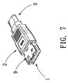
- FIG. 7 shows an assembly view of the electrical connector with grounding structure according to still another embodiment of the present invention.
- the electrical connector with grounding structure of the present invention mainly comprises: an insulating body 1 , for providing a plurality of transmitting terminals 4 inserted therein; a cable assembly 3 , comprising predetermined transmitting units 31 positioned over the transmitting terminals 4 and a jacket layer 32 with fixing and conducting effect enclosed outside the transmitting units 31 , wherein the jacket layer 32 is an aluminum foil Mylar, preferably; a grounding part 5 , comprising a contacting part 51 for contacting with the jacket layer 32 , and comprising predetermined grounding terminals 52 extended directly from the contacting part 51 for inserting into the insulating body 1 ; a conducting part 6 is enclosed over the jacket layer 32 and the grounding part 5 to improve the contact effect, wherein, the conducting part 6 is made of metal material with electrical characteristics such as copper sheet or copper ring; and an outer
- the electrical connector with grounding structure of the present invention mainly makes the grounding part 5 be inserted inside the insulating body 1 and contacted with the jacket layer 32 with fixing and conducting effect enclosed outside the transmitting units 31 , and a conducting part 6 is fully enclosed over the jacket layer 32 and the grounding part 5 , such that the grounding part 5 , the jacket layer 32 and the conducting part 6 can be fully conducted and generated electrical characteristics; thereby, the cable assembly 3 of the electrical connector has grounding effect without any grounding line positioned inside cable assembly 3 .
- the grounding part 5 comprises the contacting part 51 for contacting with the jacket layer 32 , besides it further comprises the predetermined grounding terminals 52 extended directly from the grounding part 5 for inserting into the insulating body 1 ; furthermore, both sides of the contacting portion 51 further respectively comprise a wing portion 53 to provide pressing and fitting (please refer to FIG. 4 ), so as to cause the grounding part 5 and the jacket layer 32 having better conducting effect.
- the electrical connector with grounding structure of the present invention is designed for cable assembly 3 with metal braid 7 , which comprises: an insulating body 1 , for providing a plurality of transmitting terminals 4 inserted therein; a cable assembly 3 , comprising predetermined transmitting units 31 positioned over the transmitting terminals 4 and a jacket layer 32 with fixing and conducting effect enclosed outside the transmitting units 31 , wherein the jacket layer 32 is an aluminum foil Mylar, preferably; and the jacket layer 32 is enclosed by metal braid 7 with electrical characteristics that is bent from the opening end of the cable assembly 3 from inwardly to outwardly and extended outside the cable assembly 3 ; a grounding part 5 , comprising a contacting part 51 for contacting with the jacket layer 32 , and comprising predetermined grounding terminals 52 extended directly from the grounding part 5 for inserting into the insulating
- the embodiment of the present invention mainly has made the metal housing 9 , the metal braid 7 holed by the holding portion 91 of the metal housing 9 , and conducting part 7 fully conducting to generate electrical characteristics, such that the present invention can generate a second grounding effect; therefore, the embodiment of the present invention has better electrical characteristics.
- the electrical connector with grounding structure of the present invention makes the cable assembly of the present invention has grounding effect without any grounding line positioned inside the cable assembly; furthermore, it also can lessen the soldering process and prevent the mistaken probability of the soldering process generated such that the entire assembly process and the relative cost can be reduced.
- the present invention relates to an electrical connector with grounding structure suitable for high frequency transmitting.
- the high frequency connector mainly has grounding part inserted inside the insulating body contacted with the jacket layer enclosed over the signal transmitting units with fixing and contacting effect for generating electrical characteristics, such that the cable assembly of the electrical connector has grounding effect without any grounding line positioned inside cable assembly; furthermore, it also can lessen the soldering process and prevent the mistaken probability of the soldering process generated such that the entire assembly process and the relative cost can be reduced.
Landscapes
- Details Of Connecting Devices For Male And Female Coupling (AREA)
Abstract
Description
Claims (6)
Applications Claiming Priority (1)
| Application Number | Priority Date | Filing Date | Title |
|---|---|---|---|
| TW093203973U TWM253972U (en) | 2004-03-16 | 2004-03-16 | Electric connector with grounding effect |
Publications (1)
| Publication Number | Publication Date |
|---|---|
| US7214097B1 true US7214097B1 (en) | 2007-05-08 |
Family
ID=34589033
Family Applications (1)
| Application Number | Title | Priority Date | Filing Date |
|---|---|---|---|
| US10/815,861 Expired - Fee Related US7214097B1 (en) | 2004-03-16 | 2004-04-02 | Electrical connector with grounding effect |
Country Status (2)
| Country | Link |
|---|---|
| US (1) | US7214097B1 (en) |
| TW (1) | TWM253972U (en) |
Cited By (43)
| Publication number | Priority date | Publication date | Assignee | Title |
|---|---|---|---|---|
| US20080050970A1 (en) * | 2006-08-28 | 2008-02-28 | Che-Chia Chang | Cable connector |
| US20080050968A1 (en) * | 2006-08-28 | 2008-02-28 | Che-Chia Chang | Cable connector |
| US20090197467A1 (en) * | 2008-02-01 | 2009-08-06 | Hon Hai Precision Ind. Co., Ltd. | Grounding member for cable assembly |
| US20090197468A1 (en) * | 2008-02-01 | 2009-08-06 | Hon Hai Precision Ind. Co., Ltd. | Solderness cable assembly |
| US20100015846A1 (en) * | 2008-07-18 | 2010-01-21 | Hon Hai Precision Ind. Co., Ltd. | High-speed cable assembly with protective member |
| WO2010085465A1 (en) * | 2009-01-20 | 2010-07-29 | Molex Incorporated | Plug connector with external emi shielding capability |
| US20110281464A1 (en) * | 2010-05-12 | 2011-11-17 | Hon Hai Precision Industry Co., Ltd. | Electrical connector assembly with an additional rear shell |
| CN101882728B (en) * | 2009-05-05 | 2012-10-10 | 泰科电子(上海)有限公司 | Shield clip |
| US20130130546A1 (en) * | 2011-11-23 | 2013-05-23 | Jerry Wu | Cabel end connector with connecting bar |
| US20130203283A1 (en) * | 2012-02-06 | 2013-08-08 | Alltop Electronics (Suzhou) Ltd. | Cable end connector and cable connector assembly having the same |
| US20130244482A1 (en) * | 2012-03-19 | 2013-09-19 | Fujitsu Component Limited | Contact, connector and method for manufacturing connector |
| US20150207274A1 (en) * | 2014-01-17 | 2015-07-23 | Foxconn Interconnect Technology Limited | Cable connector assembly with improved grounding structure |
| US20150295360A1 (en) * | 2013-12-10 | 2015-10-15 | Mediatek Inc. | High-speed-transmission connection device |
| US20180097326A1 (en) * | 2013-11-26 | 2018-04-05 | Samtec, Inc. | Direct-attach connector |
| US9985367B2 (en) | 2013-02-27 | 2018-05-29 | Molex, Llc | High speed bypass cable for use with backplanes |
| US10062984B2 (en) | 2013-09-04 | 2018-08-28 | Molex, Llc | Connector system with cable by-pass |
| US10135211B2 (en) | 2015-01-11 | 2018-11-20 | Molex, Llc | Circuit board bypass assemblies and components therefor |
| USRE47342E1 (en) * | 2009-01-30 | 2019-04-09 | Molex, Llc | High speed bypass cable assembly |
| US10367280B2 (en) | 2015-01-11 | 2019-07-30 | Molex, Llc | Wire to board connectors suitable for use in bypass routing assemblies |
| US10424856B2 (en) | 2016-01-11 | 2019-09-24 | Molex, Llc | Routing assembly and system using same |
| US10424878B2 (en) | 2016-01-11 | 2019-09-24 | Molex, Llc | Cable connector assembly |
| US20190305489A1 (en) * | 2016-09-09 | 2019-10-03 | HARTING Electronics GmbH | Shielding metal plate |
| US10720735B2 (en) | 2016-10-19 | 2020-07-21 | Amphenol Corporation | Compliant shield for very high speed, high density electrical interconnection |
| US10739828B2 (en) | 2015-05-04 | 2020-08-11 | Molex, Llc | Computing device using bypass assembly |
| US10840649B2 (en) | 2014-11-12 | 2020-11-17 | Amphenol Corporation | Organizer for a very high speed, high density electrical interconnection system |
| US10931062B2 (en) | 2018-11-21 | 2021-02-23 | Amphenol Corporation | High-frequency electrical connector |
| US11070006B2 (en) | 2017-08-03 | 2021-07-20 | Amphenol Corporation | Connector for low loss interconnection system |
| US11071201B2 (en) | 2017-11-14 | 2021-07-20 | Samtec, Inc. | Method and apparatus for terminating an electrical cable to an integrated circuit |
| US11101611B2 (en) | 2019-01-25 | 2021-08-24 | Fci Usa Llc | I/O connector configured for cabled connection to the midboard |
| US11151300B2 (en) | 2016-01-19 | 2021-10-19 | Molex, Llc | Integrated routing assembly and system using same |
| US11189943B2 (en) | 2019-01-25 | 2021-11-30 | Fci Usa Llc | I/O connector configured for cable connection to a midboard |
| US11205877B2 (en) | 2018-04-02 | 2021-12-21 | Ardent Concepts, Inc. | Controlled-impedance compliant cable termination |
| US11437762B2 (en) | 2019-02-22 | 2022-09-06 | Amphenol Corporation | High performance cable connector assembly |
| US11444398B2 (en) | 2018-03-22 | 2022-09-13 | Amphenol Corporation | High density electrical connector |
| US11469554B2 (en) | 2020-01-27 | 2022-10-11 | Fci Usa Llc | High speed, high density direct mate orthogonal connector |
| US11522310B2 (en) | 2012-08-22 | 2022-12-06 | Amphenol Corporation | High-frequency electrical connector |
| CN115733013A (en) * | 2021-08-25 | 2023-03-03 | 株式会社村田制作所 | Connector conversion parts and connectors |
| US11670879B2 (en) | 2020-01-28 | 2023-06-06 | Fci Usa Llc | High frequency midboard connector |
| US11735852B2 (en) | 2019-09-19 | 2023-08-22 | Amphenol Corporation | High speed electronic system with midboard cable connector |
| US11799246B2 (en) | 2020-01-27 | 2023-10-24 | Fci Usa Llc | High speed connector |
| USD1002553S1 (en) | 2021-11-03 | 2023-10-24 | Amphenol Corporation | Gasket for connector |
| US11831106B2 (en) | 2016-05-31 | 2023-11-28 | Amphenol Corporation | High performance cable termination |
| US12554918B2 (en) | 2023-10-31 | 2026-02-17 | Molex, Llc | Integrated routing assembly and system using same |
Citations (5)
| Publication number | Priority date | Publication date | Assignee | Title |
|---|---|---|---|---|
| US4501459A (en) * | 1982-12-22 | 1985-02-26 | Amp Incorporated | Electrical connector |
| US5456618A (en) * | 1991-06-26 | 1995-10-10 | Hosiden Corporation | Electrical connector |
| US5823825A (en) * | 1996-03-01 | 1998-10-20 | Molex Incorporated | System for terminating the shield of a high speed cable |
| US6299487B1 (en) * | 2000-04-03 | 2001-10-09 | Molex Incorporated | Connector with wear-resistant engagement means |
| US6722898B2 (en) * | 2001-10-17 | 2004-04-20 | Molex Incorporated | Connector with improved grounding means |
-
2004
- 2004-03-16 TW TW093203973U patent/TWM253972U/en not_active IP Right Cessation
- 2004-04-02 US US10/815,861 patent/US7214097B1/en not_active Expired - Fee Related
Patent Citations (5)
| Publication number | Priority date | Publication date | Assignee | Title |
|---|---|---|---|---|
| US4501459A (en) * | 1982-12-22 | 1985-02-26 | Amp Incorporated | Electrical connector |
| US5456618A (en) * | 1991-06-26 | 1995-10-10 | Hosiden Corporation | Electrical connector |
| US5823825A (en) * | 1996-03-01 | 1998-10-20 | Molex Incorporated | System for terminating the shield of a high speed cable |
| US6299487B1 (en) * | 2000-04-03 | 2001-10-09 | Molex Incorporated | Connector with wear-resistant engagement means |
| US6722898B2 (en) * | 2001-10-17 | 2004-04-20 | Molex Incorporated | Connector with improved grounding means |
Cited By (83)
| Publication number | Priority date | Publication date | Assignee | Title |
|---|---|---|---|---|
| US20080050968A1 (en) * | 2006-08-28 | 2008-02-28 | Che-Chia Chang | Cable connector |
| US20080050970A1 (en) * | 2006-08-28 | 2008-02-28 | Che-Chia Chang | Cable connector |
| US7819675B2 (en) * | 2008-02-01 | 2010-10-26 | Hon Hai Precision Ind. Co., Ltd. | Grounding member for cable assembly |
| US20090197467A1 (en) * | 2008-02-01 | 2009-08-06 | Hon Hai Precision Ind. Co., Ltd. | Grounding member for cable assembly |
| US20090197468A1 (en) * | 2008-02-01 | 2009-08-06 | Hon Hai Precision Ind. Co., Ltd. | Solderness cable assembly |
| US7670154B2 (en) * | 2008-02-01 | 2010-03-02 | Hon Hai Precision Ind. Co., Ltd. | Solderness cable assembly |
| US20100015846A1 (en) * | 2008-07-18 | 2010-01-21 | Hon Hai Precision Ind. Co., Ltd. | High-speed cable assembly with protective member |
| US7815445B2 (en) | 2008-07-18 | 2010-10-19 | Hon Hai Precision Ind. Co., Ltd. | High-speed cable assembly with protective member |
| WO2010085465A1 (en) * | 2009-01-20 | 2010-07-29 | Molex Incorporated | Plug connector with external emi shielding capability |
| US8439706B2 (en) | 2009-01-20 | 2013-05-14 | Molex Incorporated | Plug connector with external EMI shielding capability |
| USRE47342E1 (en) * | 2009-01-30 | 2019-04-09 | Molex, Llc | High speed bypass cable assembly |
| USRE48230E1 (en) | 2009-01-30 | 2020-09-29 | Molex, Llc | High speed bypass cable assembly |
| CN101882728B (en) * | 2009-05-05 | 2012-10-10 | 泰科电子(上海)有限公司 | Shield clip |
| US20110281464A1 (en) * | 2010-05-12 | 2011-11-17 | Hon Hai Precision Industry Co., Ltd. | Electrical connector assembly with an additional rear shell |
| US20130130546A1 (en) * | 2011-11-23 | 2013-05-23 | Jerry Wu | Cabel end connector with connecting bar |
| US8956167B2 (en) * | 2011-11-23 | 2015-02-17 | Hon Hai Precision Industry Co., Ltd. | Cable end connector with connecting bar |
| US20130203283A1 (en) * | 2012-02-06 | 2013-08-08 | Alltop Electronics (Suzhou) Ltd. | Cable end connector and cable connector assembly having the same |
| US8684770B2 (en) * | 2012-02-06 | 2014-04-01 | Alltop Electronics (Suzhou) Ltd. | Cable end connector and cable connector assembly having the same |
| US20130244482A1 (en) * | 2012-03-19 | 2013-09-19 | Fujitsu Component Limited | Contact, connector and method for manufacturing connector |
| US9431729B2 (en) * | 2012-03-19 | 2016-08-30 | Fujitsu Component Limited | Contact, connector and method for manufacturing connector |
| US11522310B2 (en) | 2012-08-22 | 2022-12-06 | Amphenol Corporation | High-frequency electrical connector |
| US11901663B2 (en) | 2012-08-22 | 2024-02-13 | Amphenol Corporation | High-frequency electrical connector |
| US10305204B2 (en) | 2013-02-27 | 2019-05-28 | Molex, Llc | High speed bypass cable for use with backplanes |
| US9985367B2 (en) | 2013-02-27 | 2018-05-29 | Molex, Llc | High speed bypass cable for use with backplanes |
| US10056706B2 (en) | 2013-02-27 | 2018-08-21 | Molex, Llc | High speed bypass cable for use with backplanes |
| US10069225B2 (en) | 2013-02-27 | 2018-09-04 | Molex, Llc | High speed bypass cable for use with backplanes |
| US10062984B2 (en) | 2013-09-04 | 2018-08-28 | Molex, Llc | Connector system with cable by-pass |
| US10181663B2 (en) | 2013-09-04 | 2019-01-15 | Molex, Llc | Connector system with cable by-pass |
| US20180097326A1 (en) * | 2013-11-26 | 2018-04-05 | Samtec, Inc. | Direct-attach connector |
| US10164394B2 (en) * | 2013-11-26 | 2018-12-25 | Samtec, Inc. | Direct-attach connector |
| US10170882B2 (en) | 2013-11-26 | 2019-01-01 | Samtec, Inc. | Direct-attach connector |
| US20150295360A1 (en) * | 2013-12-10 | 2015-10-15 | Mediatek Inc. | High-speed-transmission connection device |
| US9548573B2 (en) * | 2013-12-10 | 2017-01-17 | Mediatek Inc. | High-speed-transmission connection device having a metal protrusion electrically connected to a connector |
| US9437981B2 (en) * | 2014-01-17 | 2016-09-06 | Foxconn Interconnect Technology Limited | Cable connector assembly with improved grounding structure |
| US20150207274A1 (en) * | 2014-01-17 | 2015-07-23 | Foxconn Interconnect Technology Limited | Cable connector assembly with improved grounding structure |
| US10840649B2 (en) | 2014-11-12 | 2020-11-17 | Amphenol Corporation | Organizer for a very high speed, high density electrical interconnection system |
| US11764523B2 (en) | 2014-11-12 | 2023-09-19 | Amphenol Corporation | Very high speed, high density electrical interconnection system with impedance control in mating region |
| US10855034B2 (en) | 2014-11-12 | 2020-12-01 | Amphenol Corporation | Very high speed, high density electrical interconnection system with impedance control in mating region |
| US11621530B2 (en) | 2015-01-11 | 2023-04-04 | Molex, Llc | Circuit board bypass assemblies and components therefor |
| US10637200B2 (en) | 2015-01-11 | 2020-04-28 | Molex, Llc | Circuit board bypass assemblies and components therefor |
| US11114807B2 (en) | 2015-01-11 | 2021-09-07 | Molex, Llc | Circuit board bypass assemblies and components therefor |
| US10367280B2 (en) | 2015-01-11 | 2019-07-30 | Molex, Llc | Wire to board connectors suitable for use in bypass routing assemblies |
| US10784603B2 (en) | 2015-01-11 | 2020-09-22 | Molex, Llc | Wire to board connectors suitable for use in bypass routing assemblies |
| US10135211B2 (en) | 2015-01-11 | 2018-11-20 | Molex, Llc | Circuit board bypass assemblies and components therefor |
| US10739828B2 (en) | 2015-05-04 | 2020-08-11 | Molex, Llc | Computing device using bypass assembly |
| US11003225B2 (en) | 2015-05-04 | 2021-05-11 | Molex, Llc | Computing device using bypass assembly |
| US10424856B2 (en) | 2016-01-11 | 2019-09-24 | Molex, Llc | Routing assembly and system using same |
| US10797416B2 (en) | 2016-01-11 | 2020-10-06 | Molex, Llc | Routing assembly and system using same |
| US10424878B2 (en) | 2016-01-11 | 2019-09-24 | Molex, Llc | Cable connector assembly |
| US11108176B2 (en) | 2016-01-11 | 2021-08-31 | Molex, Llc | Routing assembly and system using same |
| US11688960B2 (en) | 2016-01-11 | 2023-06-27 | Molex, Llc | Routing assembly and system using same |
| US11842138B2 (en) | 2016-01-19 | 2023-12-12 | Molex, Llc | Integrated routing assembly and system using same |
| US11151300B2 (en) | 2016-01-19 | 2021-10-19 | Molex, Llc | Integrated routing assembly and system using same |
| US11831106B2 (en) | 2016-05-31 | 2023-11-28 | Amphenol Corporation | High performance cable termination |
| US20190305489A1 (en) * | 2016-09-09 | 2019-10-03 | HARTING Electronics GmbH | Shielding metal plate |
| US10658796B2 (en) * | 2016-09-09 | 2020-05-19 | HARTING Electronics GmbH | Shielding metal plate |
| US10720735B2 (en) | 2016-10-19 | 2020-07-21 | Amphenol Corporation | Compliant shield for very high speed, high density electrical interconnection |
| US11387609B2 (en) | 2016-10-19 | 2022-07-12 | Amphenol Corporation | Compliant shield for very high speed, high density electrical interconnection |
| US11824311B2 (en) | 2017-08-03 | 2023-11-21 | Amphenol Corporation | Connector for low loss interconnection system |
| US11637401B2 (en) | 2017-08-03 | 2023-04-25 | Amphenol Corporation | Cable connector for high speed in interconnects |
| US11070006B2 (en) | 2017-08-03 | 2021-07-20 | Amphenol Corporation | Connector for low loss interconnection system |
| US11576260B2 (en) | 2017-11-14 | 2023-02-07 | Samtec, Inc. | Method and apparatus for terminating an electrical cable to an integrated circuit |
| US11071201B2 (en) | 2017-11-14 | 2021-07-20 | Samtec, Inc. | Method and apparatus for terminating an electrical cable to an integrated circuit |
| US11444398B2 (en) | 2018-03-22 | 2022-09-13 | Amphenol Corporation | High density electrical connector |
| US11205877B2 (en) | 2018-04-02 | 2021-12-21 | Ardent Concepts, Inc. | Controlled-impedance compliant cable termination |
| US11677188B2 (en) | 2018-04-02 | 2023-06-13 | Ardent Concepts, Inc. | Controlled-impedance compliant cable termination |
| US10931062B2 (en) | 2018-11-21 | 2021-02-23 | Amphenol Corporation | High-frequency electrical connector |
| US12218462B2 (en) | 2018-11-21 | 2025-02-04 | Amphenol Corporation | High-frequency electrical connector |
| US11742620B2 (en) | 2018-11-21 | 2023-08-29 | Amphenol Corporation | High-frequency electrical connector |
| US11189943B2 (en) | 2019-01-25 | 2021-11-30 | Fci Usa Llc | I/O connector configured for cable connection to a midboard |
| US11715922B2 (en) | 2019-01-25 | 2023-08-01 | Fci Usa Llc | I/O connector configured for cabled connection to the midboard |
| US11101611B2 (en) | 2019-01-25 | 2021-08-24 | Fci Usa Llc | I/O connector configured for cabled connection to the midboard |
| US11637390B2 (en) | 2019-01-25 | 2023-04-25 | Fci Usa Llc | I/O connector configured for cable connection to a midboard |
| US11437762B2 (en) | 2019-02-22 | 2022-09-06 | Amphenol Corporation | High performance cable connector assembly |
| US11735852B2 (en) | 2019-09-19 | 2023-08-22 | Amphenol Corporation | High speed electronic system with midboard cable connector |
| US11817657B2 (en) | 2020-01-27 | 2023-11-14 | Fci Usa Llc | High speed, high density direct mate orthogonal connector |
| US11469553B2 (en) | 2020-01-27 | 2022-10-11 | Fci Usa Llc | High speed connector |
| US11469554B2 (en) | 2020-01-27 | 2022-10-11 | Fci Usa Llc | High speed, high density direct mate orthogonal connector |
| US11799246B2 (en) | 2020-01-27 | 2023-10-24 | Fci Usa Llc | High speed connector |
| US11670879B2 (en) | 2020-01-28 | 2023-06-06 | Fci Usa Llc | High frequency midboard connector |
| CN115733013A (en) * | 2021-08-25 | 2023-03-03 | 株式会社村田制作所 | Connector conversion parts and connectors |
| USD1002553S1 (en) | 2021-11-03 | 2023-10-24 | Amphenol Corporation | Gasket for connector |
| US12554918B2 (en) | 2023-10-31 | 2026-02-17 | Molex, Llc | Integrated routing assembly and system using same |
Also Published As
| Publication number | Publication date |
|---|---|
| TWM253972U (en) | 2004-12-21 |
Similar Documents
| Publication | Publication Date | Title |
|---|---|---|
| US7214097B1 (en) | Electrical connector with grounding effect | |
| US7052292B2 (en) | Grounding structure of an electrical connector | |
| US9843128B2 (en) | Waterproof electrical connector | |
| TWI769682B (en) | Electrical connector with electromagnetic shielding function | |
| US20040038564A1 (en) | Electrical connector | |
| JP2012064338A (en) | Terminal structure of coaxial cable, connector and board unit | |
| JP2010193523A (en) | Wireless transmission device with built-in antenna and connector | |
| TW202145654A (en) | Plug connector slidably inserted into receptacle connector | |
| CN113725642A (en) | Connector assembly comprising a socket connector and a plug connector | |
| US6736677B1 (en) | Cable end connector assembly with improved grounding means | |
| US9887496B2 (en) | Contact connecting of shielded data lines to a board and method for contacting a number of shielded data lines with a board | |
| KR960704372A (en) | ELECTRICAL CONNECTION ASSEMBLY | |
| US11316303B2 (en) | High frequency connector with component protecting member and method of manufacturing thereof | |
| US8251751B2 (en) | Plug and connector assembly using same | |
| SG104935A1 (en) | Cable connector and kit for assembling the same | |
| TWI238692B (en) | An electronic apparatus for the reduction of electronic magnetic interference | |
| US6824401B2 (en) | Cable end connector assembly and method of assembling the assembly | |
| CN206379500U (en) | Board to board connector and electronic equipment | |
| US11398667B2 (en) | Electronic device | |
| TWM564839U (en) | Connector | |
| JP4998741B2 (en) | Adapter structure, high-frequency cable body and wiring board connector | |
| US20150349436A1 (en) | Electrical terminal assembly | |
| CN112086785A (en) | Compact connectors for transmitting UHF signals | |
| US7232314B2 (en) | End structure of coaxial cable | |
| CN216353424U (en) | Foldable transmission flat cable structure |
Legal Events
| Date | Code | Title | Description |
|---|---|---|---|
| AS | Assignment |
Owner name: COMAX TECHNOLOGY INC., TAIWAN Free format text: ASSIGNMENT OF ASSIGNORS INTEREST;ASSIGNORS:HSU, I-CHANG;CHUO, FU-CHEN;CHIU, WEN-TA;AND OTHERS;REEL/FRAME:015178/0824 Effective date: 20040319 |
|
| AS | Assignment |
Owner name: ING, SHANG-LUN, TAIWAN Free format text: ASSIGNMENT OF ASSIGNORS INTEREST;ASSIGNOR:COMAX TECHNOLOGY, INC.;REEL/FRAME:022610/0273 Effective date: 20090413 |
|
| REMI | Maintenance fee reminder mailed | ||
| LAPS | Lapse for failure to pay maintenance fees | ||
| STCH | Information on status: patent discontinuation |
Free format text: PATENT EXPIRED DUE TO NONPAYMENT OF MAINTENANCE FEES UNDER 37 CFR 1.362 |
|
| FP | Lapsed due to failure to pay maintenance fee |
Effective date: 20110508 |