US720436A - Machine for reducing and finishing hollow bearing-balls. - Google Patents
Machine for reducing and finishing hollow bearing-balls. Download PDFInfo
- Publication number
- US720436A US720436A US10974002A US1902109740A US720436A US 720436 A US720436 A US 720436A US 10974002 A US10974002 A US 10974002A US 1902109740 A US1902109740 A US 1902109740A US 720436 A US720436 A US 720436A
- Authority
- US
- United States
- Prior art keywords
- balls
- machine
- sleeve
- rings
- feeding
- Prior art date
- Legal status (The legal status is an assumption and is not a legal conclusion. Google has not performed a legal analysis and makes no representation as to the accuracy of the status listed.)
- Expired - Lifetime
Links
Images


Classifications
-
- B—PERFORMING OPERATIONS; TRANSPORTING
- B21—MECHANICAL METAL-WORKING WITHOUT ESSENTIALLY REMOVING MATERIAL; PUNCHING METAL
- B21H—MAKING PARTICULAR METAL OBJECTS BY ROLLING, e.g. SCREWS, WHEELS, RINGS, BARRELS, BALLS
- B21H1/00—Making articles shaped as bodies of revolution
- B21H1/14—Making articles shaped as bodies of revolution balls, rollers, cone rollers, or like bodies
Definitions
- the object of this invention is to provide [0 improved means for reducing, truing, finishing, and polishing the surfaces of bearingballs,and especially hollowhearing-balls m ade from sheet metal.
- a further object of my invention is to be found in the provision of means for feeding hearing-balls automatically to and discharging the same from the finishing-machine, the feeding means being operated by the finishing-machine.
- a further ohject of my invention is to be found in the provision of means for automat-l ically increasing pressure upon a series of hearing-balls simultaneously contained in a finishing-machine.
- My invention consists in the machine for finishing bearing-balls comprisinggrooved rings, one of which is mounted for rotation, means for automatically separating the rings to receive and discharge the balls, means for automatically closing the rings gradually to a predetermined point as the balls are being rolled, and means for automatically feeding the balls to said machine.
- My invention consists, further, in the roll- 3 5 ing-machine comprising grooved rings mount- 4o bination, with a rolling and finishing machine, of means for automatically feeding a predetermined number of halls to said machine.
- My invention consists, further, in the con- 5 struction, arrangement, and combination of elements hereinafter set forth, pointed out in myjclaims, and illnstrated by the accompanying drawings, in wliich Figure 1 is an end elevation of the complete Fig. 2 is a front elevation ofthe complete machine. Fig. 3 is a plan of the machine, thc' ball receptacle being removed.
- Fig. 4 is a vertical section of the machine axially of its shaft.
- Figs. 5 and 6 are detail views of the valves.
- Fig. 7 is a detailcross-section of the feeding-tube.
- the numeral 10 designates atable on which are mounted and fixed machine heads or standards 11.12. 13 is secured at one end in a horizontal aperture or screw-seat of the machine-head 11 and projects horizontally therefrom through A shaft a materially larger aperture in the machinehead 12.
- a ring 14, preferably made of hardened steel, is mounted on the inner face of the machine-head 11 concentric with the shaft 13, and a groove 15 of annular form and preferably concaved on an arc in cross-section is formed in one face of said ring and also is arranged concentric with' the shaft 13.
- the ring'14 preferably is mounted stationary or fixed to the machine-head 11, and a notch 16 is formed in the uppermost portion of said ring and.
- a sleeve 17 is mounted for revolution on the shaft 13 between the machineheads 11 12, and a driving-pulley 18 is formed on or fixed to said sleeve and is arranged to revolve the sleeve when driven by belting to aprime mover.
- a ring 19, preferably made of hardened steel, is mounted rigidly in one end portion of the sleeve 17 concentric with theshaft 13, and agroove 20 is formed in one face ofsaid ring and is of annular form and preferably concaved on an arc in cross-section.
- the groove 20 also is concentric with the shaft 13 and is located in direct opposition to the groove 15 and is designed to cooperate with said groove in the formation of a raceway or annular seat for balls.
- the shaft 13 is threaded with a very coarse screw, the threads of which, preferably, are
- a feeding-nut 21 interiorly screw-threaded to match the coarse thread on the shaft, is mounted loosely .for rotation in the large aperture of the machine-head l2, surrounding and concentric
- Raceway rings 22 are mounted, respectively, in the inner of the feeding-nut 21 and the adjacent end portion" of the sleeve 17, end l'iGEll'lll-fb&llS ill are mounted in theracewey groove or annulus formed by said rings.
- lt is the function of the bearing-balls 21 and rings 22 23 to receive and resist the thrust of the sleeve 1'?
- a hellhearing is employed in this place to minimise the friction between the sleeve and the feeding-nut 21 and avoid rotation of said feedinq nut liy direct contact of the sleeve.
- 'Ihe ra. wa.y-rin,e 23 is of greater diameter than the sleeve 17, and a rctainingring 25, rahheted on its inner surface, is mounted around the sleeve and engages said ring.
- the retaining? ring 25 is fixed tothe feedingnnt 21 by screws 26 and serves to retain the sleeve against end Wise movement independent oi? the feedingnut.
- a post or standard 28 is mounted in and rises from the apex of the machine-head f3, and a sleeve '27 is mounted ll for revolotion or oscillation on said post.
- a torsional spring 28 is mounted around the upper end portion of the post 20 and has one of its ends in contact with the sleeve 27, while its other end is in engagement with a pin 20, fixed to and projecting from the post.
- a plate 30 is mounted on the apex of the machine-head. 11 and projects across the vertical planes of the rings 1 1- and 19, and a screwthreaded aperture is formedin said plate i1nmediately above and in registration with the notch 16 in the ring l.
- a stani'l-pipe or feeding-tube 31 is secured at its lower end in the threailed aperture oi the plate 250 and. ri.” perpendicularly therefrom.
- a hopper or re ceptacle 32 is mounted on'the upper end per-- iioa'of the stand-pipe or feeding-tube 31 and is designed to contain a quantity of hearingballs to be fed to the machine and rolled.
- a valve or gate 33 is provided, preferably of sheet metal forked at one'ond. to eznhrace those portions 01' the stand-pipe or feedingtube between the notches above mentioned and mounted for rectilinear reciprocation through said notchesv
- the lot fOImlIlg the fork at the end of the valve 3 's of width than the bore of the standpipc or tnhe ill, and said.
- valve is'notched st 534i 35, opening to the slot, the combined diameter thonotches and slot being" equal 20 or groai'crt ian. the bore of the tube.
- the valve is connected at its opposite end to a Gl;1lll(-2ll"lll3(l, fixed to and. extending horizontally from the sleeve 2 7, and the notches of the stand-pipe ele-' vated just sufdciently to permit the val-re 33 clear the pulley and belt thereon in or.- tendingto the sleeve.
- the valve 37 has notches 34C in its end portion, bordering on thcslot therein and arranged to register at tir'nes with the bore of the etand-pipe
- the valve 37 extends from the stand-pipe and has its other end pivotally connected to a crank-arm 3S, fixed to and projecting horizontally from the sleeve 27.
- the torsional spring 28 holds the sleeve 27 in such position that the crank-arm 38 re tains' the valve with its notches 3 1 out of registration with the bore of the standpipe ortnhe 31, and portions of said valve bordering the slot therein intersect and prevent the passage of the calls through said tube toward the valve
- the balls are retained in the hopper 3:1 and in that portion of the stand-pipe 31 above the valve 37 until in the operation of the machine, hereinafter described, said valve 37 is adjusted into a position to permit thefeedingof the bells through the tube to a seat on the valve
- a stub-axle or pin 89 is mounted in and extends horizontally outward from the machine head. 12 below tl1eshaft13.
- Aratchet-wheel 40 is mounted loosely for revolution 0n the pin orstub-axle 39 and retained thereon by a collar 41, attached to said. pin outside the ratchetwhcel. It is desirable to hrake'or apply a tension to the ratch .-wh.eel 40 to prevent too free movement of said ratchet-wheel on the pin 39 and to this end apin is seatod in the hub of the ratchetovheel and held in contact with the machine-head 12 by an expansive coil-spring 43, also contained in the hub of the ratchet-Wheel and hearingagainst said pin.
- a rock-shaft -14 is desirable to hrake'or apply a tension to the ratch .-wh.eel 40 to prevent too free movement of said ratchet-wheel on the pin 39 and to this end apin is seatod in the hub of the ratchetovheel and held in contact with the machine-head 12 by an
- crank-arm 4-7 on the opposite end portion of the rock'shaft 14 extends downward approximately at right anglee to the c rink-arm 45 and carries a gravity-operuted feeding-pawl 48 on its lower end.
- the feeding-pawl L8 is pivoted on the lower end portion of the crank-arm 4'7 and extends horizontall to and contacts with one or another oi the teeth of the ratchet-wheel 40 in such manner that when said crank-arm is moved in one direction the pawl will feed or revolve the ratchet-wheel predetermined distances.
- a earn-shaped shoulder 49 is formed on the ratchet-Wheel 'i-O Within the pitch-line of the teeth of said. ratchet vheel.
- the earn-shaped shoulder l?) is ap n'oxiznately circular throughout a ma or portion of the circumference of the shoulder 49. Its eccentricity to the axis of the ratchet-wheel is not great, being sufficient only to raise a traveler riding thereon to the degree necessary to perform the useful function hereinafter defined; but at one point in its periphery said shoulder is recessed or depressed a considerable and material distance, as illustrated by dottedlines in Fig. 1.
- a collar 50 is mounted on the feeding-nut 21 and secured thereto by a set-screw 51.
- the collar 50 preferably is approximately circular, and an arm 52 is formed on and radiates from said collar and is provided with a lateral stud or pin 53, extending over or across the face of the cam-shaped shoulder 49.
- An antifriction-roller 54 is mounted for revolution on the pin 53 and rides on the periphery or face of the cam-shaped shoulder 49.
- a retractile coil-spring 55 is fixed at one end to a pin 56 on the collar 50 andtat the other end is attached to a pin 57 on the table 10. It is the function of the spring 55 to hold the roller 54 in contact with the cam-shaped shoulder 49 and at the same time retain the collar 50 in a variable position governed by the eccentricity of said shoulder relative to the axis of the ratchet-wheel 40.
- the retractile coil-spring 55 draws the roller 54 into the depression or olfset portion of the shoulder 49 and in so doing rotatably moves the collar 50 a considerable distance.
- a pin 58 is fixed to and projects horizontally from the lower end portion of the sleeve 27 and extends across the face of the collar 50.
- a pin 59 is fixed to and projects laterally from the lower portion of the sleeve 27 and extends along the uppermost portion of the machine-head 12.
- the pin 59 normally engagesa pin 60, seated in the machine-head 12, and limits the movement of the sleeve in 0pposition to the expansion of the torsional spring 28.
- a pin 61 is fixed in and projects radially from the collar 50 and is arranged to engage at times with the pin 58 and move the sleeve 27 rotatably in opposition to the pressure of the torsional spring 28.
- this machine is first set with the sleeve 17 adjusted slightly away from the machine-head 11, such adjustment being effected by unscrewing the feeding-nut 21, the degree. of separation beingsufficient only to permit the passage of ballsfrom the feeding-tube or stand-pipe 31 through the notch16 into the annular space formed by the grooves and in the rings 14 and 19.
- a sufficient quantity of rough balls is introd need through the tube 3linto the annular space between the rings 14 and 19 to fill said space.
- the valve 33 is opened and the valve 37 is closed, and the hopper and uppermost portion of the stand-pipe 31 are filled or supplied with rough balls.
- the feedin g-n ut is adjusted to cause the ring 19 to bear slightly upon the balls, which contact at their opposite portions with the ring 14,and the ratchet-wheel is adjusted so that the roller 54 is at the initial point 00 of the cam-shaped shoulder49.
- the pawl48 is positioned on and in contact with a tooth of the ratchetwheel 40, and the machine is started by gearing to the prime mover. (Not shown.)
- the rough balls are revolved, rolled, and worn between the rings 14 and 19, inasmuch as the ring 14 is stationary and the ring 19 revolves with the sleeve.
- crank-arm 45 In the revolution of the sleeve 17 the camrib 46 revolves and acts upon and vertically oscillates the crank-arm 45.
- the vertical oscillation of the crank-arm results in an oscillation of the rock-shaft 44 and a consequent horizontal oscillation of the crank-arm 47.
- the horizontal oscillation of the crankarm 47 effects a rectilinear reciprocation of the feeding-pawl 4S,and said pawl in turn engages successive teeth of the ratchet-wheel and rotatably moves said wheel step by step in a given direction.
- ratchet-wheel in a given direction (indicated by the arrow at in Fig.
- the ratchet-wheel is made in twoparts, the ratchet proper being formed on a rim 40, secured by screws 40" to the plate portion, the cam-shaped shoulder 49 forming the periphery of the plate portion.
- Such construction is adopted in consideration of shaping and truing the periphery of the plate portion of the cam-shaped shoulder.
- a machine for rolling hollow balls grooved rings, one of which'is mounted for rotation,automatic mechanism for separating the rings to allow the balls to travel into the grooves thereof, and automatic mechanism to close the rings gradually to a predetermined point as the balls are being rolled.
- a shaft,counterpart grooved rings one of which revolves around said shaft, mechanism ar-' ranged to reciprocate the revolving ring longitudinally of its axis synchronous with its rotation, and a feeder consisting of a tube and a gate therein and arranged to allowthe balls to enter said grooved rings at predetermined intervals.
- a shaft in a machine for rolling hollow balls, a shaft, counterpart grooved rings,one of which revolves around said shaft and is arranged for endwise reciprocation longitudinally of the shaft synchronous with its revolution,and a feeder provided with feeding mechanism automatically to allow a plurality of balls to enter said grooved rings at predetermined intervals.
- a receptacle for the balls arranged to receive the balls from the receptacle by gravity, gates arranged to hold back the balls from the machine a predetermined length of time, and mechanism acting on said gates to pass the balls to the machine in predetermined numbers, and feed the balls within the machine, together with automatic discharging mechanism whereby the balls maybe discharged from the machine after they have been rolled.
- a shaft for truing and condensing hollow metal balls
- a receptacle for holding balls mounted above said machine
- a feeder arranged to carry the balls by gravity to said machine, and means arranged to retain the balls within the grooves of the rings and means for automatically discharging the balls after they have been rolled.
- rings is mounted forautomatic and synchronous rotation on and reciprocation longitudinally of said shaft, and driving mechanism arranged to control said rotation and reciprocation.
- a shaft in a machine for rolling hollow balls, a shaft, counterpart grooved rings, one of which reciprocates endwise of said shaft, a cam arranged to control said reciprocation, and a timing-ratchet arranged to control the feeding of the balls with reference to the operation of the cam.
- a feeder provided with a cam-operated controlling-gate, and a timing-ratchet arranged to control the operation of said gate.
- a shaft in a machine for truing and condensing hollow metal balls, a shaft, counterpart grooved rings, one of which revolves around said shaft, means for distributing a plurality of balls within the grooves of said rings, and means for automatically discharging the balls after they have been trued.
- a shaft in a machine for truing and condensing hollow metal balls, a shaft, counterpart grooved rings, one of which revolves around said shaft, means for automatically distributing and retaining a plurality of balls within said grooves, and means for discharging the balls after they have been rolled a predetermined length of time.
- the machine-heads the shaft fixed to one of said heads, the grooved ring mounted on said sleeve in opposition to the first grooved ring, and cam-operated screw mechanism arranged to feed said sleeve longitudinally of said shaft.
- the reducing-ring stationarily mounted, the reducingring mounted for rotation in opposition thereto, the feeding mechanism arranged to move said rotatable reducing-ring longitudinally of its aXis, the cam acting on said feeding mechanism and the ratchet-andpawl mechanism acting on said cam and operated by the rotation of the rotatable reducingring.
- the machine-head fixed therein and having a coarse screw on its opposite end
- the reducing-ring on the machine-head the sleeve mounted for revolution on the shaft, the reducing-ring on the sleeve in opposition to the first reducing-ring
- means for feeding balls to the space between said rings the feeding-nut having a coarse screw in mesh with the coarse screw of the shaft, ball-bearings interposed between the feeding-nut and the adjacent end of the sleeve, a retaining-ring connecting the feeding-nut and sleeve, a cam arranged to move said feeding-nut rotatably, and rat tribend-pawl mechanism acting on said cam and geared to the revoluble sleeve.
- the machine-head the shaft fixed therein and having a coarse screw on its opposite end
- the reducing-ring on the machine-head the sleeve mounted for revolution on the shaft, the reducing-ring on the sleeve in opposition to the first reducing-ring
- means for feeding balls to the space between said rings the feedingnut having a coarse screw in mesh with the coarse screw of the shaft, ball-bearings interposed between the feeding-nut and the adjacent end of the sleeve, a cam arranged to move said feeding-nut rotatably, and rat tribend-pawl mechanism acting on said cam and geared to the revoluble sleeve, together with a rock-shaft, and a cam-rib on said sleeve acting on said arm.
- rolling mechanism consisting of counterpart grooved rings one of which revolves, automatic mechanism arranged to of its axis synchronous with its rotation, a receptacle for balls, a conductor and automatically-operated stops in said conductor to allow a series of a predetermined number .of balls to pass to the rolling mechanism and to prevent passage of further balls through the conductor until said first series have been rolled through the entire length of the grooves of the rings a predetermined plural number of times and discharged. 4
- feeding mechanism to automatically approach said rings as the balls are being rolled and also to separate said rings and discharge said balls after they have been rolled.
- the grooved rings one mounted for synchronous rotation and endwise reciprocation, ball-feeding mechanism and ringfeeding mechanism whereby the rotatable ring may be separated from the other ring, the balls fed in series to the grooves of the rings and the rotatable ring returned to ballrolling relation with the other ring, successively and repetitiously simultaneous with the rotation thereof.
Description
No. 720,436. PATENTED FEB. 10; 1903.
A. JOHNSTON. MACHINE FOR REDUCING AND FINISHING'HOLLOW BEARING BALLS.
APPLIOATfON FILED MAY 31, 1902. b I
110 MODEL, 4 SHEETS-SHEET 1 INF ii nguumu No. 720,436. 7 PATENTED FEB. 10, 1903.
I A. JOHNSTON. I MACHINE FOR REDUGING AND FINISHING HOLLOW BEARING BALLS.
APPLICATION FILED MAY 31,1902. I
NO MODEL. 4 SHBETSSHEET 2.
No. 720,436. PATBNTED FEB. 10,1903.
' A. JOHNSTON. MACHINE FOR REDUCING AND FINISHING HOLLOW BEARING BALLS.
. APPLICATION FILED MAY 31, 1902. N0 MODEL,
4 SHEETS-SHEET 3- A. JOHNSTON. MACHINE FOR REDUCING AND FINISHI 7 no MODEL,
APPLICATION FILED MAY 31, 1902.
I v 4 SHEBTS SHEET 4.
PATENTED FEB. 10, 1903.
Ne HOLLOW BEARING BALLS.
5 machine.
Nirnn STATES ALLEN JOHNSTON, or OTTUMWA, IOWA.
MACHINE FOR REDUCING AND FINISHING HOLLOW BEARING-BALLS.
SPEGIFIGATION forming part of Letters Patent No. 720,436, dated February 10, 1903.
Application filed May 31, 1902. Serial No- 109,740. (No model.)
To all whom it may concern:
Be it known that I, ALLEN J ormsron, a citi- Len of the United States of America, and a resident of Ottumwa, Wapello county, Iowa,
. have invented anew and.usetul Machine for Reducing and Finishing Hollow Bearing- Balls, of which the following is a specification.
The object of this invention is to provide [0 improved means for reducing, truing, finishing, and polishing the surfaces of bearingballs,and especially hollowhearing-balls m ade from sheet metal.
A further object of my invention is to be found in the provision of means for feeding hearing-balls automatically to and discharging the same from the finishing-machine, the feeding means being operated by the finishing-machine. l
A further ohject of my invention is to be found in the provision of means for automat-l ically increasing pressure upon a series of hearing-balls simultaneously contained in a finishing-machine.
My invention consists in the machine for finishing bearing-balls comprisinggrooved rings, one of which is mounted for rotation, means for automatically separating the rings to receive and discharge the balls, means for automatically closing the rings gradually to a predetermined point as the balls are being rolled, and means for automatically feeding the balls to said machine.
' My invention consists, further, in the roll- 3 5 ing-machine comprising grooved rings mount- 4o bination, with a rolling and finishing machine, of means for automatically feeding a predetermined number of halls to said machine. I 1
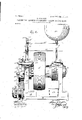
My invention consists, further, in the con- 5 struction, arrangement, and combination of elements hereinafter set forth, pointed out in myjclaims, and illnstrated by the accompanying drawings, in wliich Figure 1 is an end elevation of the complete Fig. 2 is a front elevation ofthe complete machine. Fig. 3 is a plan of the machine, thc' ball receptacle being removed.
Fig. 4 is a vertical section of the machine axially of its shaft. Figs. 5 and 6 are detail views of the valves. Fig. 7is a detailcross-section of the feeding-tube.
In the construction of the machine and its mounting, as shown, the numeral 10 designates atable on which are mounted and fixed machine heads or standards 11.12. 13 is secured at one end in a horizontal aperture or screw-seat of the machine-head 11 and projects horizontally therefrom through A shaft a materially larger aperture in the machinehead 12. A ring 14, preferably made of hardened steel, is mounted on the inner face of the machine-head 11 concentric with the shaft 13, and a groove 15 of annular form and preferably concaved on an arc in cross-section is formed in one face of said ring and also is arranged concentric with' the shaft 13. The ring'14 preferably is mounted stationary or fixed to the machine-head 11, and a notch 16 is formed in the uppermost portion of said ring and. communicates with the groove 15 therein. A sleeve 17 is mounted for revolution on the shaft 13 between the machineheads 11 12, and a driving-pulley 18 is formed on or fixed to said sleeve and is arranged to revolve the sleeve when driven by belting to aprime mover. (Not shown.) A ring 19, preferably made of hardened steel, is mounted rigidly in one end portion of the sleeve 17 concentric with theshaft 13, and agroove 20 is formed in one face ofsaid ring and is of annular form and preferably concaved on an arc in cross-section. The groove 20 also is concentric with the shaft 13 and is located in direct opposition to the groove 15 and is designed to cooperate with said groove in the formation of a raceway or annular seat for balls.
the shaft 13 is threaded with a very coarse screw, the threads of which, preferably, are
angular in cross-section, and a feeding-nut 21, interiorly screw-threaded to match the coarse thread on the shaft, is mounted loosely .for rotation in the large aperture of the machine-head l2, surrounding and concentric As above stated, one end portion of the shaft 13 is threaded and secured in the mawith said shaft, Raceway rings 22 are mounted, respectively, in the inner of the feeding-nut 21 and the adjacent end portion" of the sleeve 17, end l'iGEll'lll-fb&llS ill are mounted in theracewey groove or annulus formed by said rings. lt is the function of the bearing-balls 21 and rings 22 23 to receive and resist the thrust of the sleeve 1'? end wise or longitudinally of the shaft 13, and a hellhearing is employed in this place to minimise the friction between the sleeve and the feeding-nut 21 and avoid rotation of said feedinq nut liy direct contact of the sleeve. 'Ihe ra. wa.y-rin,e 23 is of greater diameter than the sleeve 17, and a rctainingring 25, rahheted on its inner surface, is mounted around the sleeve and engages said ring. The retaining? ring 25 is fixed tothe feedingnnt 21 by screws 26 and serves to retain the sleeve against end Wise movement independent oi? the feedingnut. i
A post or standard 28 is mounted in and rises from the apex of the machine-head f3, and a sleeve '27 is mounted ll for revolotion or oscillation on said post. A torsional spring 28 is mounted around the upper end portion of the post 20 and has one of its ends in contact with the sleeve 27, while its other end is in engagement with a pin 20, fixed to and projecting from the post.
A plate 30 is mounted on the apex of the machine-head. 11 and projects across the vertical planes of the rings 1 1- and 19, and a screwthreaded aperture is formedin said plate i1nmediately above and in registration with the notch 16 in the ring l. A stani'l-pipe or feeding-tube 31 is secured at its lower end in the threailed aperture oi the plate 250 and. ri." perpendicularly therefrom. A hopper or re ceptacle 32 is mounted on'the upper end per-- iioa'of the stand-pipe or feeding-tube 31 and is designed to contain a quantity of hearingballs to be fed to the machine and rolled. finished, reduced, and polished therein, At a little distance above the plate 30 notches are formed in the slamlpipe or feeding-tube 31, which notches intersect the here of the tribe and are on opposite sides of the center thereofi A valve or gate 33 is provided, preferably of sheet metal forked at one'ond. to eznhrace those portions 01' the stand-pipe or feedingtube between the notches above mentioned and mounted for rectilinear reciprocation through said notchesv The lot fOImlIlg the fork at the end of the valve 3 's of width than the bore of the standpipc or tnhe ill, and said. valve is'notched st 534i 35, opening to the slot, the combined diameter thonotches and slot being" equal 20 or groai'crt ian. the bore of the tube. The valve is connected at its opposite end to a Gl;1lll(-2ll"lll3(l, fixed to and. extending horizontally from the sleeve 2 7, and the notches of the stand-pipe ele-' vated just sufdciently to permit the val-re 33 clear the pulley and belt thereon in or.- tendingto the sleeve. Normally the torsional spring 23? nolds the sleeve 23 in such positimi that the notches 85 elf the valve are in registration with the bore of the stendpipe or tube 31 and permit the passage of the halls downwardly through said tube. At a material distance shove the valve the standpipe or tube 31 is again notched in like man.- next, and a valve 37, also forked at one end, is mounted for rectilinear reciprocation through said notches and across the plane of the stand.- pipe. The valve 37 has notches 34C in its end portion, bordering on thcslot therein and arranged to register at tir'nes with the bore of the etand-pipe The valve 37 extends from the stand-pipe and has its other end pivotally connected to a crank-arm 3S, fixed to and projecting horizontally from the sleeve 27. Hermally the torsional spring 28 holds the sleeve 27 in such position that the crank-arm 38 re tains' the valve with its notches 3 1 out of registration with the bore of the standpipe ortnhe 31, and portions of said valve bordering the slot therein intersect and prevent the passage of the calls through said tube toward the valve Thus normally the balls are retained in the hopper 3:1 and in that portion of the stand-pipe 31 above the valve 37 until in the operation of the machine, hereinafter described, said valve 37 is adjusted into a position to permit thefeedingof the bells through the tube to a seat on the valve A stub-axle or pin 89 is mounted in and extends horizontally outward from the machine head. 12 below tl1eshaft13. Aratchet-wheel 40 is mounted loosely for revolution 0n the pin orstub-axle 39 and retained thereon by a collar 41, attached to said. pin outside the ratchetwhcel. It is desirable to hrake'or apply a tension to the ratch .-wh.eel 40 to prevent too free movement of said ratchet-wheel on the pin 39 and to this end apin is seatod in the hub of the ratchetovheel and held in contact with the machine-head 12 by an expansive coil-spring 43, also contained in the hub of the ratchet-Wheel and hearingagainst said pin. A rock-shaft -14. s mounted for os eillation in a hearing fixed to the machinehead 12, and a crank-arm on said r0ckshnl't extends across the vertical plane of the she f .lo' and contacts with an eccentric boss or (3ZtFIl--I'lll 46 on the sleeveli adjacent the retaining--ring 25. A crank-arm 4-7 on the opposite end portion of the rock'shaft 14 extends downward approximately at right anglee to the c rink-arm 45 and carries a gravity-operuted feeding-pawl 48 on its lower end. The feeding-pawl L8 is pivoted on the lower end portion of the crank-arm 4'7 and extends horizontall to and contacts with one or another oi the teeth of the ratchet-wheel 40 in such manner that when said crank-arm is moved in one direction the pawl will feed or revolve the ratchet-wheel predetermined distances. A earn-shaped shoulder 49 is formed on the ratchet-Wheel 'i-O Within the pitch-line of the teeth of said. ratchet vheel.
The earn-shaped shoulder l?) is ap n'oxiznately circular throughout a ma or portion of the circumference of the shoulder 49. Its eccentricity to the axis of the ratchet-wheel is not great, being sufficient only to raise a traveler riding thereon to the degree necessary to perform the useful function hereinafter defined; but at one point in its periphery said shoulder is recessed or depressed a considerable and material distance, as illustrated by dottedlines in Fig. 1. A collar 50 is mounted on the feeding-nut 21 and secured thereto by a set-screw 51. The collar 50 preferably is approximately circular, and an arm 52 is formed on and radiates from said collar and is provided with a lateral stud or pin 53, extending over or across the face of the cam-shaped shoulder 49. An antifriction-roller 54 is mounted for revolution on the pin 53 and rides on the periphery or face of the cam-shaped shoulder 49. A retractile coil-spring 55 is fixed at one end to a pin 56 on the collar 50 andtat the other end is attached to a pin 57 on the table 10. It is the function of the spring 55 to hold the roller 54 in contact with the cam-shaped shoulder 49 and at the same time retain the collar 50 in a variable position governed by the eccentricity of said shoulder relative to the axis of the ratchet-wheel 40. When the ratchet-wheel in its rotation under the influence of the stepby-step movement of the feeding-pawl 48 shall have performed almost a complete revolution, the retractile coil-spring 55 draws the roller 54 into the depression or olfset portion of the shoulder 49 and in so doing rotatably moves the collar 50 a considerable distance. A pin 58 is fixed to and projects horizontally from the lower end portion of the sleeve 27 and extends across the face of the collar 50. A pin 59 is fixed to and projects laterally from the lower portion of the sleeve 27 and extends along the uppermost portion of the machine-head 12. The pin 59 normally engagesa pin 60, seated in the machine-head 12, and limits the movement of the sleeve in 0pposition to the expansion of the torsional spring 28. A pin 61 is fixed in and projects radially from the collar 50 and is arranged to engage at times with the pin 58 and move the sleeve 27 rotatably in opposition to the pressure of the torsional spring 28.
For practical operation this machine is first set with the sleeve 17 adjusted slightly away from the machine-head 11, such adjustment being effected by unscrewing the feeding-nut 21, the degree. of separation beingsufficient only to permit the passage of ballsfrom the feeding-tube or stand-pipe 31 through the notch16 into the annular space formed by the grooves and in the rings 14 and 19. Thus a sufficient quantity of rough balls is introd need through the tube 3linto the annular space between the rings 14 and 19 to fill said space. Then the valve 33 is opened and the valve 37 is closed, and the hopper and uppermost portion of the stand-pipe 31 are filled or supplied with rough balls. Then the feedin g-n ut is adjusted to cause the ring 19 to bear slightly upon the balls, which contact at their opposite portions with the ring 14,and the ratchet-wheel is adjusted so that the roller 54 is at the initial point 00 of the cam-shaped shoulder49. The pawl48 is positioned on and in contact with a tooth of the ratchetwheel 40, and the machine is started by gearing to the prime mover. (Not shown.) In the rotation of the pulleylS and sleeve 17 in either direction the rough balls are revolved, rolled, and worn between the rings 14 and 19, inasmuch as the ring 14 is stationary and the ring 19 revolves with the sleeve. In the revolution of the sleeve 17 the camrib 46 revolves and acts upon and vertically oscillates the crank-arm 45. The vertical oscillation of the crank-arm results in an oscillation of the rock-shaft 44 and a consequent horizontal oscillation of the crank-arm 47. The horizontal oscillation of the crankarm 47 effects a rectilinear reciprocation of the feeding-pawl 4S,and said pawl in turn engages successive teeth of the ratchet-wheel and rotatably moves said wheel step by step in a given direction. ratchet-wheel in a given direction (indicated by the arrow at in Fig. 1) the roller 54 rises slightly on the incline or cam-shaped periphery of the shoulder 49, and'in rising said roller 54 raises the pin 53 and arm 52 and rotatably moves the collar and feeding-nut 21 in a given direction, (indicated by the arrow 1) in Fig. 2.) In the rotation of the feeding-nut, as indicated by the arrow i) in Fig. 2, said nut engages by its screw with the coarse screw of the shaft 13 andoperating through the ball-bearing,consisting of the rings22, 23, and balls 24, tends to move and does move the sleeve 17 endwise and approximates or brings closer the ring 19 to the ring 14. It will be perceived that the endwise movement of the sleeve 17 coincident with any one step of advance of the ratchet-wheel 40 is infinitesimal, but of apositive and measurable quantity, andthat such endwise movement supplies a slightly-increased pressure to the rough balls being treated between the rings 14 and 19. The relative diameters of the rings 14 19 and the ratchet-wheel 40 are such that when the ratchet-wheel has almost completed a revolution and the terminal por tion y of the cam-shaped shoulder 49 is in contact with the roller 54 the balls being treated between said rings have received a considerable and material reduction of diameter and have been turned and pressed on their various axes and polished, worn, smoothed, and finished to the desired degree of perfection. Thereafter in the further operation of the machine and continued rotation of the ratchet-wheel the roller 54 moves inward toward the axis of the ratchet-wheel and along the surface of the depressed portion of the shoulder 49, being impelled by the retractile resilience of the spring 55. It is apparent that as the roller 54 enters the depressed portion of the shoulder 49 its move- In the rotation of the ment isaccelerated and it rapidly unscrews the feeding-nut 21 and withdraws the sleeve 17 and separates the ring 19 from the ring 14. Such degree of separation of the ring 19 from the ring 14 permits the discharge of all the balls contained between said rings into a receptacle 62, provided to receive them. Such reversed and accelerated movement of the roller 54 and collar 50 is arrested when the roller reaches the limit of depression in the shoulder and is overcome and invert-ed by the rise of said roller on the opposite incline of the shoulder. When the collar moves rapidly in a direction opposite to that indicated by the arrow 1) in Fig. 2 by reason of the roller 54 entering the depression of the shoulder 49, the feeding-nut 21 is rapidly unscrewed and separates the rings 14 and 19 for the deposit of the balls in the receptacle 62. 54 rises on the opposite incline of the depressed portion of the shoulder 49 the feeding-nut 21 is again screwed upon the shaft and moves the sleeve 17 sufficiently to approach the ring 19 toward the ring 14 enough to prevent the escape of the balls from the space between the red [icing-rings. When the collar 50 moves in a direction opposite to that indicated by the arrow b in Fig. 1 by reason of the roller 54 entering the depressed portion of the shoulder 49, said collar removes the pin 61 from the pin 58 and permits the sleeve 27 to move rotatably under the resilience of the torsional spring 28 exerted on the crank- -arm 38, such movement of rotation of the sleeve continuing until it is arrested by contact of the pin 59 with the pin 60. In such movement of rotation of the sleeve 27 the crank- arms 36 and 38 move away from the stand-pipe or feeding-tube 31 and in so doing move the valves 33 and 37 longitudinally until the feeding-port of the valve 33 is closed and the feeding-port of the valve 37 is opened, whereby a quantity of the balls may flow from the receptacle 32 into and fill the space between said valves. As the roller 54 rises on the opposite incline of the depressed portion of the shoulder 49 toward the point a it moves the collar 50 rotatably in the direction of the arrow b until the pin 61 contacts with the pin 58 and moves said pin 58 to the right, thus establishing a movement of rotation of the sleeve 27 against the resilience of the torsional spring 28. While the ratchet-wheel is traveling from the point z to the point z the valve 33 is opened and the valve 37 is closed, thus permitting the deposit of the quantity of balls measured between said valves into the annular space formed by the grooves 15 and 20 in the rings 14 and 19, said balls entering the annular space through the notch 16. As the roller 54 rises from the point z to the point 0c and gradually from the point a: to the point y the valves are held with the lower one open and the upper one closed by contact of the pin 61 with the pin 58 against the resilience of the torsional spring 28. The abrupt elevation of the cam between the point z and As the roller the point 00 is provided to enter the feedingnut 21 quickly in such position as will move the sleeve 17 and reducing-ring 19 endwise until such reducing-ring contacts with the balls in the grooves and causes said balls to contact with the reducing-ring 14. This operation also closes the rings sufficiently that the balls may not thereafter escape through the notch or entrance-port 16. Further operations of the machine are repetitions of those just described and are continued until the quantity of balls in the receptacle 43 is exhausted or the machine is stopped by disengagement from the prime mover.
Reference to the drawings will disclose that the ratchet-wheel is made in twoparts, the ratchet proper being formed on a rim 40, secured by screws 40" to the plate portion, the cam-shaped shoulder 49 forming the periphery of the plate portion. Such construction is adopted in consideration of shaping and truing the periphery of the plate portion of the cam-shaped shoulder.
It will be observed that the balls in the annular space between the rings 14 and 19 are acted upon or revolved or carried about in their orbit a very large number of times while confined in the machine and before being discharged therefrom. Such repeated and multiplied treatment of the balls is desirable in order to produce that smoothness and uniform circularity of surface as is required for the attainment of the most satisfactory results and is provided for by arranging a high speed of the pulley 18 relative to the slow feed of the sleeve 17 endwise under the influence of the ratchet-wheel and cam-shaped shoulder acting upon the feeding-nut 21. It will be observed that in the treatment of a quantity of balls by the reducing- rings 14 and 19 the pressure applied thereto by endwise thrust or feed of the sleeve 17 is very gradual and uniformly progressive-that is to say, the feed of the sleeve endwise can progress no faster than the rotation of the ratchet-wheel and the shape of the cam-shaped shoulder 49 will permit, and yet at each revolution of the pulley 18 and sleeve 17 an endwise movement of the, sleeve is effected in some degree. The product resulting from the treatment of the balls is an object of truly spherical character, having material homogeneity of substance and uniformly hard and polished surface.
I do not wish to be understood as limiting myself to the use of a tube or stand-pipe in vertical position for feeding the rough balls to the rolls, since myinvention is ofbroader scope and compasses a large variety of ball feedingorsupplyingmechanisms. Neitherdo I wish to be limited to the use of the precise form of sleeve-feeding mechanism employed, as various screw-operated feeding devices or step-by-step mechanisms may be devised to efiect an endwise movement of the revolving sleeve or the head in opposition thereto.
I claim as my invention-- 1. In a machine for rolling hollow balls, grooved rings, one of which'is mounted for rotation,automatic mechanism for separating the rings to allow the balls to travel into the grooves thereof, and automatic mechanism to close the rings gradually to a predetermined point as the balls are being rolled.
2. In a machine for rolling hollow balls, grooved rings, one of which is mounted for rotation, automatic mechanism for separating the rings to allow the balls to drop out, an automatic mechanism to close the rings partially to allow the balls to passinto the grooves thereof and then gradually to close the rings to a predetermined point as the balls are being rolled. I
3. In a machine for rolling hollowballs, counterpart grooved rings, one of which is stationary and the other revolves, and means for automatically reciprocating the revolving ring longitudinally of its axis synchronous with its rotation.
4. In a machine for rolling hollow balls, a shaft,counterpart grooved rings, one of which revolves around said shaft, mechanism ar-' ranged to reciprocate the revolving ring longitudinally of its axis synchronous with its rotation, and a feeder consisting of a tube and a gate therein and arranged to allowthe balls to enter said grooved rings at predetermined intervals.
5. In a machine for rolling hollow balls, a shaft, counterpart grooved rings,one of which revolves around said shaft and is arranged for endwise reciprocation longitudinally of the shaft synchronous with its revolution,and a feeder provided with feeding mechanism automatically to allow a plurality of balls to enter said grooved rings at predetermined intervals.
6. In a machine for rolling hollow balls, counterpart grooved rings, one of which revolves, and automatic mechanism to reciprocate the revolving ring longitudinally of its axis synchronous with its revolution.
7. In a machine for rolling hollow balls, a receptacle for the balls, a feeder arranged to receive the balls from the receptacle by gravity, gates arranged to hold back the balls from the machine a predetermined length of time, and mechanism acting on said gates to pass the balls to the machine in predetermined numbers, and feed the balls within the machine, together with automatic discharging mechanism whereby the balls maybe discharged from the machine after they have been rolled.
8. In a machine for truing and condensing hollow metal balls, a shaft, counterpart grooved rings, one of which revolves around the shaft, a receptacle for holding balls mounted above said machine, a feeder arranged to carry the balls by gravity to said machine, and means arranged to retain the balls within the grooves of the rings and means for automatically discharging the balls after they have been rolled.
rings is mounted forautomatic and synchronous rotation on and reciprocation longitudinally of said shaft, and driving mechanism arranged to control said rotation and reciprocation.
11. In a machine for rolling hollow balls, a shaft, counterpart grooved rings, one of which reciprocates endwise of said shaft, a cam arranged to control said reciprocation, and a timing-ratchet arranged to control the feeding of the balls with reference to the operation of the cam.
12. In a machine for rolling hollow balls, a feeder provided with a cam-operated controlling-gate, and a timing-ratchet arranged to control the operation of said gate.
13. In a machine for truing and condensing hollow metal balls, a shaft, counterpart grooved rings, one of which revolves around said shaft, means for distributing a plurality of balls within the grooves of said rings, and means for automatically discharging the balls after they have been trued.
14. In a machine for truing and condensing hollow metal balls, a shaft, counterpart grooved rings, one of which revolves around said shaft, means for automatically distributing and retaining a plurality of balls within said grooves, and means for discharging the balls after they have been rolled a predetermined length of time.
15. In a machine for rolling hollow balls, the machine-heads, the shaft fixed to one of said heads, the grooved ring mounted on said sleeve in opposition to the first grooved ring, and cam-operated screw mechanism arranged to feed said sleeve longitudinally of said shaft.
16. The combination of the reducing-machine,antomatic mechanism arranged to open and close the reducing-machine for the reception and discharge of balls synchronous with the revolution thereof, the stand-pipe communicating therewith and arranged to feed balls thereto,the ball'containin g receptacle on said stand-pipe, the valves controlling the number in each series of balls passing through said stand-pipe and the cam-operated mechanism arranged to move said valves for alternate opening and closing thereof.
17. The combination of the reducing-machine, the stand-pipe communicating therewith, the receptacle on the stand-pipe, the valves controlling said stand-pipe, and the cam-operated, spring-resisted mechanism whereby the valves are moved to and fro in reciprocate the revolving ring longitudinally the operation of the machine.
18. The reducing-ring stationarily mounted, the reducingring mounted for rotation in opposition thereto, the feeding mechanism arranged to move said rotatable reducing-ring longitudinally of its aXis, the cam acting on said feeding mechanism and the ratchet-andpawl mechanism acting on said cam and operated by the rotation of the rotatable reducingring.
19. In a machine of the class described, the machine-head, the shaft fixed therein and having a coarse screw on its opposite end, the reducing-ring on the machine-head, the sleeve mounted for revolution on the shaft, the reducing-ring on the sleeve in opposition to the first reducing-ring, means for feeding balls to the space between said rings, the feeding-nut having a coarse screw in mesh with the coarse screw of the shaft, ball-bearings interposed between the feeding-nut and the adjacent end of the sleeve, a retaining-ring connecting the feeding-nut and sleeve, a cam arranged to move said feeding-nut rotatably, and ratchetand-pawl mechanism acting on said cam and geared to the revoluble sleeve.
20. In a machine of the class described, the machine-head, the shaft fixed therein and having a coarse screw on its opposite end, the reducing-ring on the machine-head, the sleeve mounted for revolution on the shaft, the reducing-ring on the sleeve in opposition to the first reducing-ring, means for feeding balls to the space between said rings, the feedingnut having a coarse screw in mesh with the coarse screw of the shaft, ball-bearings interposed between the feeding-nut and the adjacent end of the sleeve, a cam arranged to move said feeding-nut rotatably, and ratchetand-pawl mechanism acting on said cam and geared to the revoluble sleeve, together with a rock-shaft, and a cam-rib on said sleeve acting on said arm.
21. In a machine for rolling a series of balls simultaneously, rolling mechanism consisting of counterpart grooved rings one of which revolves, automatic mechanism arranged to of its axis synchronous with its rotation, a receptacle for balls, a conductor and automatically-operated stops in said conductor to allow a series of a predetermined number .of balls to pass to the rolling mechanism and to prevent passage of further balls through the conductor until said first series have been rolled through the entire length of the grooves of the rings a predetermined plural number of times and discharged. 4
22. In a machine for rolling hollow balls, grooved rings, one of whiclfrevolves, a conductor, gates on said conductor to allow a plurality of balls to pass in series to said rings,
at predetermined times and in predetermined numbers, feeding mechanism to automatically approach said rings as the balls are being rolled and also to separate said rings and discharge said balls after they have been rolled.
23. In a machine for rolling hollow balls, grooved rings, one of which revolves, a conductor and gates thereon to allow a plurality of balls to pass in series to said rings at predetermined times and in predetermined numbers, feeding mechanism to automatically approach said rings as the balls are being rolled and also to separate said rings and discharge said balls after they have been rolled, and timing mechanism to control said movements.
24. In a machine for rolling and reducing hollow balls, the grooved rings, one mounted for synchronous rotation and endwise reciprocation, ball-feeding mechanism and ringfeeding mechanism whereby the rotatable ring may be separated from the other ring, the balls fed in series to the grooves of the rings and the rotatable ring returned to ballrolling relation with the other ring, successively and repetitiously simultaneous with the rotation thereof.
Signed by me at 'Ottumwa, Iowa, this 26th day of April, 1902.
ALLEN JOHNSTON.
WVitnesses:
R. W. FUNK, FRED DIMMITT.
Priority Applications (1)
| Application Number | Priority Date | Filing Date | Title |
|---|---|---|---|
| US10974002A US720436A (en) | 1902-05-31 | 1902-05-31 | Machine for reducing and finishing hollow bearing-balls. |
Applications Claiming Priority (1)
| Application Number | Priority Date | Filing Date | Title |
|---|---|---|---|
| US10974002A US720436A (en) | 1902-05-31 | 1902-05-31 | Machine for reducing and finishing hollow bearing-balls. |
Publications (1)
| Publication Number | Publication Date |
|---|---|
| US720436A true US720436A (en) | 1903-02-10 |
Family
ID=2788951
Family Applications (1)
| Application Number | Title | Priority Date | Filing Date |
|---|---|---|---|
| US10974002A Expired - Lifetime US720436A (en) | 1902-05-31 | 1902-05-31 | Machine for reducing and finishing hollow bearing-balls. |
Country Status (1)
| Country | Link |
|---|---|
| US (1) | US720436A (en) |
-
1902
- 1902-05-31 US US10974002A patent/US720436A/en not_active Expired - Lifetime
Similar Documents
| Publication | Publication Date | Title |
|---|---|---|
| US2927333A (en) | Assembling machine | |
| US720436A (en) | Machine for reducing and finishing hollow bearing-balls. | |
| US1926974A (en) | Grinding machine | |
| US2373155A (en) | Machine tool | |
| US2013A (en) | Machine foe making pins | |
| US2632345A (en) | Apparatus for forming rods, bolts, or the like | |
| US1282610A (en) | Machine for loading cartridges. | |
| US1010740A (en) | Machine for threading sheet-metal caps. | |
| US1101675A (en) | Machine for making solid balls. | |
| US251874A (en) | Machine for rolling th reads of screws or bolts | |
| US3552600A (en) | Dispenser for like-sized balls | |
| US668180A (en) | Bolt-head-trimming machine. | |
| US480017A (en) | The hdrria peters co | |
| USRE21425E (en) | Dough twisting machine | |
| US235921A (en) | Burnish ing-machine | |
| US428572A (en) | Island | |
| US1080798A (en) | Process of making solid balls. | |
| US581459A (en) | Machine for spirally impressing wire or the like | |
| US418456A (en) | Machine for forming eyes on wire bands | |
| US1043005A (en) | Can-head-lining machine. | |
| US383949A (en) | Screw-swaging machine | |
| US604057A (en) | leayitt | |
| US1601655A (en) | Winding machine | |
| US155920A (en) | Improvement in machines for screw-threading rods | |
| US1373051A (en) | Method and mechanism for finishing rolls |