US7200078B2 - Method and related optical disk accessing apparatus for calibrating optical disk tilt servo system according to non-constant relation between locations and tilt angles of optical disk - Google Patents
Method and related optical disk accessing apparatus for calibrating optical disk tilt servo system according to non-constant relation between locations and tilt angles of optical disk Download PDFInfo
- Publication number
- US7200078B2 US7200078B2 US10/709,030 US70903004A US7200078B2 US 7200078 B2 US7200078 B2 US 7200078B2 US 70903004 A US70903004 A US 70903004A US 7200078 B2 US7200078 B2 US 7200078B2
- Authority
- US
- United States
- Prior art keywords
- optical disk
- tilt
- locations
- calibration
- disk drive
- Prior art date
- Legal status (The legal status is an assumption and is not a legal conclusion. Google has not performed a legal analysis and makes no representation as to the accuracy of the status listed.)
- Expired - Lifetime, expires
Links
Images


Classifications
-
- G—PHYSICS
- G11—INFORMATION STORAGE
- G11B—INFORMATION STORAGE BASED ON RELATIVE MOVEMENT BETWEEN RECORD CARRIER AND TRANSDUCER
- G11B27/00—Editing; Indexing; Addressing; Timing or synchronising; Monitoring; Measuring tape travel
- G11B27/10—Indexing; Addressing; Timing or synchronising; Measuring tape travel
- G11B27/19—Indexing; Addressing; Timing or synchronising; Measuring tape travel by using information detectable on the record carrier
- G11B27/24—Indexing; Addressing; Timing or synchronising; Measuring tape travel by using information detectable on the record carrier by sensing features on the record carrier other than the transducing track ; sensing signals or marks recorded by another method than the main recording
-
- G—PHYSICS
- G11—INFORMATION STORAGE
- G11B—INFORMATION STORAGE BASED ON RELATIVE MOVEMENT BETWEEN RECORD CARRIER AND TRANSDUCER
- G11B7/00—Recording or reproducing by optical means, e.g. recording using a thermal beam of optical radiation by modifying optical properties or the physical structure, reproducing using an optical beam at lower power by sensing optical properties; Record carriers therefor
- G11B7/08—Disposition or mounting of heads or light sources relatively to record carriers
- G11B7/09—Disposition or mounting of heads or light sources relatively to record carriers with provision for moving the light beam or focus plane for the purpose of maintaining alignment of the light beam relative to the record carrier during transducing operation, e.g. to compensate for surface irregularities of the latter or for track following
- G11B7/0945—Methods for initialising servos, start-up sequences
-
- G—PHYSICS
- G11—INFORMATION STORAGE
- G11B—INFORMATION STORAGE BASED ON RELATIVE MOVEMENT BETWEEN RECORD CARRIER AND TRANSDUCER
- G11B7/00—Recording or reproducing by optical means, e.g. recording using a thermal beam of optical radiation by modifying optical properties or the physical structure, reproducing using an optical beam at lower power by sensing optical properties; Record carriers therefor
- G11B7/08—Disposition or mounting of heads or light sources relatively to record carriers
- G11B7/09—Disposition or mounting of heads or light sources relatively to record carriers with provision for moving the light beam or focus plane for the purpose of maintaining alignment of the light beam relative to the record carrier during transducing operation, e.g. to compensate for surface irregularities of the latter or for track following
- G11B7/095—Disposition or mounting of heads or light sources relatively to record carriers with provision for moving the light beam or focus plane for the purpose of maintaining alignment of the light beam relative to the record carrier during transducing operation, e.g. to compensate for surface irregularities of the latter or for track following specially adapted for discs, e.g. for compensation of eccentricity or wobble
- G11B7/0956—Disposition or mounting of heads or light sources relatively to record carriers with provision for moving the light beam or focus plane for the purpose of maintaining alignment of the light beam relative to the record carrier during transducing operation, e.g. to compensate for surface irregularities of the latter or for track following specially adapted for discs, e.g. for compensation of eccentricity or wobble to compensate for tilt, skew, warp or inclination of the disc, i.e. maintain the optical axis at right angles to the disc
-
- G—PHYSICS
- G11—INFORMATION STORAGE
- G11B—INFORMATION STORAGE BASED ON RELATIVE MOVEMENT BETWEEN RECORD CARRIER AND TRANSDUCER
- G11B7/00—Recording or reproducing by optical means, e.g. recording using a thermal beam of optical radiation by modifying optical properties or the physical structure, reproducing using an optical beam at lower power by sensing optical properties; Record carriers therefor
- G11B7/12—Heads, e.g. forming of the optical beam spot or modulation of the optical beam
- G11B7/125—Optical beam sources therefor, e.g. laser control circuitry specially adapted for optical storage devices; Modulators, e.g. means for controlling the size or intensity of optical spots or optical traces
- G11B7/126—Circuits, methods or arrangements for laser control or stabilisation
- G11B7/1267—Power calibration
-
- H—ELECTRICITY
- H03—ELECTRONIC CIRCUITRY
- H03L—AUTOMATIC CONTROL, STARTING, SYNCHRONISATION OR STABILISATION OF GENERATORS OF ELECTRONIC OSCILLATIONS OR PULSES
- H03L7/00—Automatic control of frequency or phase; Synchronisation
- H03L7/06—Automatic control of frequency or phase; Synchronisation using a reference signal applied to a frequency- or phase-locked loop
- H03L7/08—Details of the phase-locked loop
Definitions
- the present invention provides a method and related apparatus for calibrating a tilt servo system of an optical disk drive, and more particularly, a tilt servo system calibration method and related apparatus for surface bend according to a physical model showing that the optical disk has different degrees of radial tilt at different locations.
- optical disk storage device such as optical disk drives and CD players
- FIG. 1 illustrates a block diagram of a prior art optical disk drive 10
- FIG. 2 is a lateral view diagram of the optical disk drive 10 along a sectioning-line 2 — 2
- the optical disk drive 10 includes a control module 20 , a tilt servo system 22 , and related mechanical and electrical structures for data access, such as a motor 16 , a track 14 , a sled 12 A, and a pick-up head 12 B.
- the control module 20 controls operation of the optical disk drive 10 ; the motor 16 rotates an optical disk 18 .
- the sled 12 A slides along the track 14 .
- the pick-up head 12 B set on the sled 12 A emits a laser beam to the optical disk 18 , and can access data at different locations on the optical disk 18 .
- the laser beam from the pick-up head 12 B should be accurately focused on the optical disk 18 for data access (including reading data from the optical disk, or writing/burning data to the optical disk). Therefore, after focusing the laser beam on a surface 24 of the optical disk 18 (see FIG. 2 ), the pick-up head 12 B detects a laser reflection from the optical disk 18 then generates a corresponding signal which is returned to the control module 20 . The control module 20 determines whether the pick-up head 12 B has already focused the laser beam accurately on the optical disk 18 according to the received reflection.
- the control module 20 can control a servomechanism on the sled 12 A with a servo signal Fp to fine tune the location of the pick-up head 12 B up and down (along an arrow 26 in FIG. 2 ), so as to adjust the distance between the pick-up head 12 B and the optical disk 18 .
- the control module 20 adjusts/calibrates the distance between the pick-up head 12 B and the optical disk 18 with the servo signal Fp.
- the pick-up head 12 B can finally focus on the optical disk 18 accurately.
- the pick-up head 12 B can focus exactly on the surface 24 of the optical disk 18 , and if the servo signal Fp is greater than the standard servo signal Fs 0 , the sled 12 A is driven to raise the pick-up head 12 B by the servo signal Fp; that is, if a location of the surface 24 is fixed, the corresponding servo signal Fp triggers the sled 12 A to maintain, increase, or decrease the distance between the pick-up head 12 B and the surface 24 based on whether the servo signal Fp is equal to, greater, or smaller than the servo signal Fs 0 .
- the value of the servo signal Fp corresponds to the vertical position of the pick-up head 12 B.
- the optical disk drive 10 includes a tray or equivalent mechanism to bear the optical disk 18 .
- the surface of the optical disk 18 should remain parallel to the pick-up head 12 B for steady data access.
- the optical disk drive 10 further includes a tilt servo system 22 , which determines how to adjust the angle between the surface 24 and the pick-up head 12 B according to the servo signal Fp provided by the control module 20 .
- a tilt servo system 22 determines how to adjust the angle between the surface 24 and the pick-up head 12 B according to the servo signal Fp provided by the control module 20 .
- FIG. 3 , FIG. 4 also FIG. 1 and FIG. 2 ).
- FIG. 2 , FIG. 3 and FIG. 4 are also lateral view diagrams of the optical disk drive 10 .
- FIG. 2 if the surface 24 of the optical disk 18 parallels the pick-up head 12 B, a distance D between the sled 12 A and the surface 24 is exactly equal to the distance D 0 , hence the pick-up head 12 B focuses on the surface 24 accurately.
- FIG. 2 illustrates a horizontal projection 28 with a dotted line, which is in a plane parallel to the pick-up head 12 B.
- FIG. 3 illustrates, a non-zero angle exists between the surface 24 and the horizontal plane of the pick-up head 12 B, i.e.
- the surface 24 is no longer perpendicular with respect to the focus (vertical) axis of the pick-up head. Therefore, the distance between the surface 24 and the sled 12 A deviates from the distance D 0 to the upper side of the horizontal 28 (as shown in FIG. 3 , the disk 18 has effectively risen upward, so the distance D is greater than the distance D 0 ). Because the surface 24 rises, the pick-up head 12 B cannot focus on the optical disk accurately, and so, referring again to FIG. 3 , the focusing feedback control mechanism between the pick-up head 12 B and the control module 20 takes effect.
- the control module 20 drives the servomechanism of the sled 12 A with a servo signal Fp greater than the standard servo signal Fs 0 , so that the pick-up head 12 B rises along an arrow 27 A in compensation, to the end that the pick-up head 12 B can focus accurately on the surface 24 once more.
- the tilt servo system 22 also monitors the servo signal Fp provided by the control module 20 . If the servo signal Fp is greater than the standard servo signal Fs 0 , the tilt servo system 22 determines the surface 24 has already deviated from the horizontal 28 , because the control module 20 has increased the servo signal Fp in order to re-focus the pick-up head 12 B on the surface 24 . In this situation, the tilt servo system 22 starts adjusting the angle between the optical disk 18 and the pick-up head 12 B. As FIG.
- the tilt servo system 22 lowers the optical disk 18 along the arrow 27 C, which effectively lowers the surface 24 toward its original vertical position above the pick-up head 12 B. While the tilt servo system 22 adjusts the tilt of the optical disk 18 , the focusing feedback control mechanism between the control module 20 and the pick-up head 12 B decreases the servo signal Fp gradually until the surface 24 returns to the horizontal 28 . As a result, the distance D between the surface 24 and the sled 12 A returns to a value equal to the distance D 0 , and the servo signal Fp from a value greater than the standard servo signal Fs 0 in FIG.
- the tilt servo system 22 determines whether tilt servo operation has been completed, that is, whether the surface 24 is once more coincident to the horizontal 28 . Hence, the tilt servo system 22 finishes adjusting tilt angle. In conclusion, the tilt servo system 22 adjusts the tilt angle of the tray with the servomechanism, or equivalently changes the vertical position relationship between the optical disk 18 (and hence the surface 24 ) and the pick-up head 12 B.
- the tilt servo system 22 adjusts the distance between the optical disk 18 and the pick-up head 12 B until the servo signal Fp is equal to the standard servo signal Fs 0 . Because operations of the tilt servo system 22 are based on the standard servo signal Fs 0 , measurement and calibration of the standard servo signal Fs 0 becomes a key point.
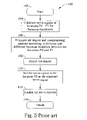
- FIG. 5 also FIG. 1 and FIG. 2 ) illustrating a prior art process 100 , which shows a process of the optical disk drive 10 in FIG. 1 calibrating the tilt servo system 22 .
- Process 100 includes the following steps:
- FIG. 6 To further illustrate the prior art process 100 , please refer to FIG. 6 , FIG. 7 , and FIG. 8 , which continue on from FIG. 1 to FIG. 4 .
- the surface 24 of the optical disk 18 is not parallel to the horizontal 28 , which means the optical drive 10 should undergo process 100 first.
- the sled 12 A seeks the location P 0 where the servo signal Fp provided by the focusing feedback control mechanism is hypothetically equal to a signal f 0 .
- the distance between the surface 24 and the horizontal 28 at the location P 0 is hypothetically equal to a distance Yp 0 (or equivalently a distance between the surface 24 and the sled 12 A).
- the sled 12 A moves to another location P 1 , a distance DX 0 apart from the location P 0 , where the servo signal Fp is hypothetically equal to a signal f 1 , which corresponds to the distance between the surface 24 and the sled 12 A at the location P 1 (or a distance Yp 1 ).
- the control module 20 applies a greater servo signal Fp to the pick-up head 12 B in the location P 1 for accurate focus.
- the difference in servo signal Fp between the locations P 1 and P 0 corresponds to the difference in vertical height of the surface 24 between the locations P 1 and P 0 (also the difference between distances Yp 1 and Yp 0 ).
- process 100 estimates overall tilt angle of the surface 24 based on the assumption that the surface is a perfect plane in, step 106 .
- the tilt servo system 22 compensates according to the angle A 1 along the arrow 27 C in step 108 (wherein a dotted line 25 represents the position of the optical disk 18 in FIG. 6 and FIG. 7 ). Therefore, if the surface 24 of the optical disk 18 is indeed a perfect plane, the surface 24 should be parallel to the horizontal 28 after compensation. Then, in step 110 , the sled 12 A returns to the location P 0 , while the current servo signal Fp provided by the focusing feedback control mechanism is set for the standard servo signal Fs 0 . As a result, the tilt servo system 22 starts to act (step 112 ), and finishes calibration (step 114 ), so as to facilitate accessing of the optical disk 18 .
- the calibration provided by the tilt servo system in the prior art process 100 is carried out under the assumption that the surface of the optical disk is a perfect plane.
- the surfaces of optical disks are not perfect planes, but may be subject to slight bending or ‘dishing’, the extent of which cannot be seen by the naked eye (in the order of micrometers).
- optical disk bend can cause many negative effects. More especially in that the presence of bending undermines the assumption that the surface is a perfect plane, the prior art process 100 fails to calibrate the correct standard servo signal, to the end that the tilt servo system cannot access data properly.
- FIG. 9 and FIG. 10 are also lateral view diagrams.
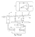
- FIG. 9 and FIG. 10 show exaggerated bending of the surface 24 for convenience. It can be seen that different locations on the surface may have varying degrees of tilt. As FIG. 9 illustrates, a point P is a hypothetical fulcrum when the tilt servo system 22 calibrates the surface 24 . Additionally, vertical lines through the locations P 0 and P 1 intersect the surface 24 at points Pa 0 and Pa 1 , and a horizontal line projected from the point Pa 0 intersects the vertical line passing through the point Pa 1 at a point Pa 01 .
- an included angle exists between a line from the point Pa 0 to the point P and the horizontal 28
- another included angle A 1 exists between a line from the point Pa 1 to the point Pa 0 and a line from the point Pa 0 to the point Pa 01 (see FIG. 9 or its inset graph 9 A).
- the angle A is not equal to the angle A 1 .
- the prior art process 100 can only estimate the angle A 1 with the distances DX 0 and DY 0 , but not the angle A. That is, the prior art process 100 can only estimate the included angle of surface bend between two points and cannot compensate for variations in included angle across the wider data area of the optical disk 18 .
- FIG. 10 illustrates calibration error when adjusting for surface bend in step 108 .
- the prior art process 100 compensates according to the angle A 1 along the arrow 27 C in step 108 , only the line from the point Pa 0 to the point Pa 1 is parallel to the horizontal 28 , while an included angle (A-A 1 ) still exists between the line from the point P to the point Pa 0 and the horizontal 28 .
- the pick-up head 12 B again calibrates the servo signal Fp at the location P 0 in step 110 , the surface 24 still deviates from the horizontal 28 . Therefore, as FIG.
- a calibration error occurs, which means that the surface 24 near the location P 0 (or near the point Pa 0 ) is not horizontal. If, in subsequent operations, the tilt servo system 22 always takes this standard servo signal Fs 0 as a reference, the tilt servo system 22 will not operate properly and neither will the focusing feedback control mechanism.
- the prior art process 100 in FIG. 5 is based on the assumption that the surface is a perfect plane, the prior art technique relies on readings from only two locations for the whole surface tilt estimation.
- the surfaces of optical disks are generally bent or dished to some degree and in such a way that their surfaces have different degrees of tilt at different locations. That is, the prior art process 100 cannot derive a correct standard servo signal, with the result that the tilt servo system 22 cannot adjust the tilt surface precisely. Consequently, the optical disk drive 10 may suffer from degradation of data read-back signals.
- an optical disk drive can focus a laser beam on an optical disk and receive a reflection
- a method and apparatus for calibrating the optical disk tilt servo system of an optical disk drive includes:
- FIG. 1 illustrates a block diagram of a prior art optical disk drive.
- FIG. 2 illustrates a lateral view diagram of the optical disk drive in FIG. 1 .
- FIG. 3 and FIG. 4 illustrate schematic diagrams of the optical disk drive in FIG. 1 during tilt servo system operation.
- FIG. 5 illustrates a flowchart of the prior art calibration process of the optical disk drive in FIG. 1 .
- FIG. 6 , FIG. 7 , and FIG. 8 illustrate schematic diagrams of the optical disk drive in FIG. 1 during the calibration process in FIG. 5 .
- FIG. 9 and FIG. 10 illustrate schematic diagrams of the optical disk drive in FIG. 1 during the process in FIG. 5 for a surface bend.
- FIG. 11 illustrates a block diagram of the present invention, an optical disk drive.
- FIG. 12 illustrates a flowchart of the optical disk drive calibration process in FIG. 11 .
- FIG. 13 and FIG. 14 illustrate schematic diagrams of the optical disk drive in FIG. 11 during the calibration process in FIG. 12 .
- FIG. 15 illustrates a schematic diagram of the optical disk drive in FIG. 11 during tilt servo system operation.
- FIG. 16 and FIG. 17 illustrate schematic diagrams of the optical disk drive in FIG. 11 during the process in FIG. 12 with another physical model for a surface bend.
- FIG. 18 illustrates a schematic diagram of the optical disk drive in FIG. 11 including an alternative type of tilt servo system.
- the optical disk drive 30 includes a sled 32 A, a pick-up head 32 B, a track 34 , a motor 36 , a control module 40 , a tilt servo system 42 , a calculation module 48 , and a calibration module 46 .
- the motor 36 rotates an optical disk 38 ; the sled 32 A slides along the track 34 , which carries the pick-up head 32 B to emit a laser beam to the optical disk 38 . While the sled 32 A leads the pick-up head 32 B to slide along the track 14 , the pick-up head 32 B can access data stored on the optical disk 38 .
- the control module 40 controls the operation of the optical disk drive 30 .
- the pick-up head 32 B After focusing the laser beam on the optical disk 38 , the pick-up head 32 B detects a reflection from the optical disk 38 , and then generates a corresponding signal back to the control module 40 , so as to determine focusing condition.
- the control module 40 triggers a servomechanism of the sled 32 A with a servo signal F for moving the pick-up head 32 B up and down, so that the pick-up head 32 B can maintain precise focusing on the surface. For that reason, a focusing feedback control mechanism is included between the pick-up head 32 B and the control module 40 . Similar to the optical disk drive 10 in FIG. 1 , the optical disk drive 30 in FIG.
- the 11 also includes a tilt servo system 42 , which can adjust the tilt angle between the optical disk 38 and the pick-up head 32 B based on the servo signal F provided by the control module 40 .
- the tilt servo system 42 is also referenced to a standard servo signal for determining tilt angle, therefore, before the tilt servo system 42 commences operation, the optical disk drive 30 undergoes a calibration process for setting the value of the standard servo signal.
- the present invention adopts a physical model for surface bend. That is, the calibration module 46 sets a standard location and at least two calibration locations according to the physical model (which means there are at least three different locations to be calibrated, and the number of these locations is determined by the physical model).
- the control module 40 controls the sled 32 A to move the pick-up head 32 B to these locations where each instance of servo signal F provided by the focusing feedback control mechanism, is used to estimate the tilt angle of the surface.
- the calculation module 48 calculates related parameters of the physical model, so as to calibrate the tilt angle of surface bend at different locations.
- the tilt servo system 42 can adjust/correct the tilt of an optical disk 38 based on the tilt angle at different locations, i.e. in accordance with the physical model, so that the servo signal of the standard location can be set at a level suitable for surface bend.
- FIG. 12 also FIG. 11 , which illustrates a calibration process 200 when the optical disk drive 30 calibrates the tilt servo system.
- the process 200 includes the following steps:
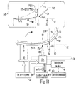
- process 200 please refer to FIG. 13 (also FIG. 11 ), which illustrates a lateral view diagram along a sectioning line 13 — 13 in FIG. 11 .
- the physical model in FIG. 13 is based on an embodiment that treats the variation in tilt angle of the surface versus distance as a linear polynomial.
- the sled 32 A carrying the pick-up head 32 B moves to the standard location S 0 and two calibration locations S 1 and S 2 , where the focusing feedback control mechanism operates for three corresponding servo signals F.
- the focusing feedback control mechanism can adjust the servo signal F for the pick-up head 32 B to accurately focus on the surface 50 , so that the servo signals F represents surface 50 undulation in the calibration locations.
- FIG. 13 illustrates, in step 206 , the calculation module 48 is able to calculate different vertical distances DY 1 and DY 2 by calculating different servo signals F between the locations S 1 and S 0 , and between the locations S 2 and S 0 .
- lines through the locations S 0 , S 1 , and S 2 being perpendicular to a horizontal 52 parallel with the pick-up head 32 B, intersect the surface 50 at points Pb 0 , Pb 1 , and Pb 2 , so that distances DY 1 and DY 2 represent different vertical distances between the points Pb 1 and Pb 0 , and between the points Pb 2 and Pb 0 .
- distances DX 1 and DX 2 represent horizontal distances between the locations S 1 and S 0 , and between the locations S 2 and S 0 , which can be calculated by measuring corresponding distances between locations on the track 34 .
- an included angle T between a line from the point S to the point Pb 0 and a line of the horizontal 52 represents the tilt angle of the surface 50 in the standard location S 0 .
- the calculation module 48 is able to estimate tilt angles corresponding to the calibration locations S 1 and S 2 in step 206 .
- An angle T 1 between the line Pb 1 to Pb 0 and the horizontal 52 represents a tilt angle corresponding to the calibration location S 1
- an angle T 2 between the line Pb 2 to Pb 0 represents a tilt angle corresponding to the calibration location S 2 .
- the angles T 1 and T 2 can be DY 1 /DX 1 and DY 2 /DX 2 , so process 200 determines whether DY 1 /DX 1 is equal to DY 2 /DX 2 in step 208 (or whether the difference between DY 1 /DX 1 and DY 2 /DX 2 is smaller than a threshold value). If true, the angle T 1 is (almost) equal to the angle T 2 . Therefore, the surface 50 can be regarded as a perfect plane, to the end that process 200 proceeds to step 210 . Contrarily, if false, the surface 50 is regarded as having surface bend as FIG. 13 illustrates, with the result that process 200 proceeds to step 212 instead, where parameters of the physical model are calculated for simulating the surface bend 52 .
- the angle T and the parameter b are unknown, but the angles T 1 and T 2 can be obtained from DY 1 /DX 1 and DY 2 /DX 2 .
- a system of two equations (as graph 13 A illustrates) can be used to calculate the parameter b and the angle T.
- the embodiment in FIG. 13 needs to calibrate tilt angle in two calibration locations, so as to construct the system of two equations, and then solve them.
- process 200 can further include other locations for calibration, which can construct redundant systems of equations so as to solve the parameters b and T with the least-square error method.
- the physical model can simulate the surface 50 bend.
- a compensating amount DYt corresponding to the standard location can be obtained.
- a compensating amount DYt can be obtained by calculation at the calibration location S 1 , that is: if the servo signal F of the location S 1 corresponds to the compensating amount DYt, the tilt servo system 42 can simply adjust the location S 0 to horizontal. Therefore, in step 214 , the sled 32 A moves to the location S 1 , where the tilt servo system 42 adjusts the tilt angle of the surface 50 .
- the focusing feedback control mechanism continues changing the value of the servo signal F until the servo signal F corresponds to the compensating amount DYt.
- the tilt angle of the surface 50 corresponding to the location S 0 is adjusted to an estimation of the horizontal.
- the sled 32 A carrying the pick-up head 32 B returns to the standard location S 0 , where the servo signal F provided by the focusing feedback control mechanism becomes the standard servo signal F 0 .
- the tilt servo system 42 should, in this case, move in the opposite direction (in FIG. 13 , the direction is downward), so as to decrease the angle T to zero.
- the tilt angle corresponding to the calibration location S 1 (also the angle between the line Pb 0 to Pb 1 and the horizontal 52 ) becomes T 1 -T.
- the vertical height of the surface 50 at the location S 1 (compared with that at location S 0 ) should be DY 1 ⁇ T*DX 1 , which is also the compensating amount DYt.
- FIG. 14 illustrates schematic diagrams of steps 214 and 216 , in which the tilt servo system 42 has already adjusted the surface 50 along an arrow 47 A with the compensating amount DYt.
- a dotted line 51 in FIG. 14 illustrates the surface 50 in FIG. 13 (the surface before adjustment).
- the vertical position of the surface 50 at the location S 1 (Pb 1 ) with respect to the vertical position the surface 50 at the location S 0 (Pb 0 ) is the distance DY 1 , while in FIG.
- the same dimension corresponds to the compensating amount DYt.
- process 200 determines if the surface 50 is horizontal according to the servo signal F at the calibration location S 1 if equal to the compensating amount DYt, which is equal to DY 1 ⁇ T*DX 1 in the case of FIG. 13 , but equal to zero when the surface is a perfect plane.
- the focusing feedback control mechanism After step 214 , and the surface 50 near the location S 0 has been adjusted to the horizontal, so that, in step 216 , when the sled 32 A returns to the location S 0 , the focusing feedback control mechanism generates the standard servo signal F 0 (as FIG. 14 illustrates).
- process 200 carries out steps 218 and 220 , where the tilt servo system 42 operates with the standard servo signal F 0 .
- FIG. 15 illustrates a schematic diagram of the tilt servo system 42 operating when the optical disk drive 30 in FIG. 11 accesses data.
- the tilt servo system 42 adjusts the tilt angle of the surface 50 during data access, to the end that the servo signal F is always close to the standard servo signal F 0 .
- the tilt servo system 42 still adjusts locations of the surface 50 corresponding to the horizontal position of the pick-up head 32 B, to the horizontal according to the servo signal F if it (servo signal F) deviates from the standard servo signal F 0 .
- the prior art assumes the surface is a perfect plane with equivalent tilt angles at different locations, so that the prior art cannot adequately accommodate surface bend.
- the present invention can have another implementation if the optical disk drive 30 includes preferred operation resources, which can represent a bent surface with another physical model.
- the optical disk drive 30 includes preferred operation resources, which can represent a bent surface with another physical model.
- process 200 includes calibrating three different calibration locations S 1 , S 2 , and S 3 during step 204 (see FIG. 12 ).
- step 214 the tilt servo system 42 adjusts the surface 50 , so that near the standard location S 0 it is corrected to an estimation of the horizontal (a dotted line 53 represents the surface 50 in FIG. 16 ).
- the vertical position of the surface 50 at the location S 1 (Pb 1 ) with respect to the vertical position of the surface 50 at the location S 0 should be the compensating amount DYt, i.e. DY 1 ⁇ T*DX 1 .
- control module 40 the calibration module 46 , and the calculation module 48 can be combined onto one chip.
- the embodiments in FIGS. 13 , 14 , 16 , and 17 assume the surface 50 is bent upward, the present invention is also suitable for a downward bend.
- the parameter b should be negative, so that the tilt angle decreases as distance increases.
- the pick-up head 32 B is hypothetically parallel to the horizontal, and the tilt servo system 42 hypothetically adjusts the included angle between the surface and the pick-up head for tilt improvement.
- tilt servo systems of some optical disk drives can change the angle of the pick-up head 32 B to adjust the included angle between the surface and the pick-up head, but the embodiments of the present invention are certainly suitable for this case.
- the optical disk drive 30 further includes another tilt servo system 62 , which adjusts the direction of the pick-up head 32 B along an arrow 47 B with a special servomechanism, so as to adjust the relative angle of the pick-up head to the surface 50 .
- the present invention is still able to fit this system for calibrating surface bend.
- the prior art calibrates the tilt servo system under the assumption that the surface of the optical disk is a perfect plane, but the assumption is not always applicable to surfaces of optical disks, as they are generally bent or dished to some extent. Therefore, the prior art cannot calibrate the tilt servo system accurately, and further decreases the efficiency and correctness of data access.
- the present invention adopts the physical model which can change the tilt angle adjustment of the surface as the location (radial position) changes, so that the calibration process can accurately set the standard servo signal for the tilt servo system to allow it to adjust the optical disk surface 18 during data access. As a result, accuracy and efficiency of data access in the optical disk drive can be promoted.
Landscapes
- Physics & Mathematics (AREA)
- Optics & Photonics (AREA)
- Optical Recording Or Reproduction (AREA)
- Signal Processing For Digital Recording And Reproducing (AREA)
- Stabilization Of Oscillater, Synchronisation, Frequency Synthesizers (AREA)
Abstract
Description
-
- step 102: start calibration of the
tilt servo system 22. (Process 100 includes calibrating and setting the standard servo signal Fs0 for thetilt servo system 22 before data is accessed, but after a disk is inserted into theoptical disk drive 10. As mentioned above, both blemishes/irregularities of the optical disk drive (or other support devices for the optical disk 18) and surface bend of theoptical disk 18 cause tilt and vertical deviation of thesurface 24, so that when inserting a disk, the standard servo signal Fs0 of thetilt servo system 22 may be in error and should ideally be calibrated after the tilt servo). - step 104: the sled 12A carrying the pick-
up head 12B seeks two different locations, P0 and P1, along the track 14 (please refer toFIG. 2 ), where the focusing feedback control mechanism between the pick-up head 12B and thecontrol module 20 is engaged. As mentioned above, the focusing feedback control mechanism adjusts value of the servo signal Fp, so as to move the pick-up head 12B up and down for accurate focus on thesurface 24. Additionally, owing to the fixed focus point of the pick-up head 12B, the vertical position of the pick-up head 12B will correspond to any undulation of thesurface 24 and the servo signal Fp should change accordingly. Therefore, the value of the servo signal Fp at the locations P0 and P1 represent any undulation of the surface 24 (or deviation from the horizontal). Therefore, the greater the difference in the servo signal Fp between the locations P0 and P1, the more deviation from the horizontal there is in theoptical disk 18. Taking the values of the servo signal Fp at the locations P0 and P1, theprior art process 100 calibrates tilt of thesurface 24. - step 106: according to an assumption that a surface is a perfect plane,
process 100 estimates the overall tilt angle of thesurface 24 away from the horizontal 28 based on the difference in vertical height between the locations P0 and P1. After that,process 100 determines a compensating amount required for thesurface 24 to be returned to the horizontal 28. - step 108: according to the compensating amount in
step 106, thetilt servo system 22 adjusts theoptical disk 18, so as to return thesurface 24 to the horizontal 28. - step 110: the
sled 12A carrying the pick-up head 12B seeks the location P0 again and the focusing feedback control mechanism acts to find focus. The resulting value of the servo signal Fp corresponding to the location P0 is set as the standard servo signal Fs0. Therefore, theprocess 100 finishes setting the standard servo signal Fs0. AsFIG. 2 ,FIG. 3 , andFIG. 4 illustrate, the servo signal Fp should be equal to the standard servo signal Fs0 if thesurface 24 is horizontal. Furthermore, the function of thetilt servo system 22 is to maintain a minimum differential between the servo signal Fp and the standard servo signal Fs0, or equivalently to maintain the disposition of thesurface 24 in the horizontal plane. Since theprior art process 100 calibrates and adjusts the tilt angle under the assumption that optical disks are perfect planes, thesurface 24 should be horizontal afterstep 108 where the servo signal Fp is taken as the standard servo signal Fs0. - step 112: after setting the standard servo signal Fs0, the
tilt servo system 22 acts with reference to the standard servo signal Fs0. - step 114:
finish process 100. Theoptical disk drive 10 starts accessing theoptical disk 18, while thetilt servo system 22 continues to adjust tilt angle, so that the servo signal Fp is always close to the standard servo signal Fs0 set instep 110.
- step 102: start calibration of the
- step 202: start the calibration process 200 (which begins before data is accessed, but after an
optical disk 30 is inserted). - step 204: setting a standard location S0 and at least two calibration locations S1, S2. The
sled 32A moves to these locations where the focusing feedback control mechanism sets each servo signal F. The focusing feedback control mechanism triggers the servo signals F to move thesled 32A in the vertical sense, so as to adjust/maintain distance between the pick-uphead 32B and the surface of the optical disk. Therefore, each servo signal corresponding to each location represents undulation of the surface. In other words, taking these servo signals as indications of disk bend allows the estimation of tilt angle in the above locations. - step 206: taking into account the different distances and focusing results between each calibration location and the standard location S0, tilt angle at each calibration location can be determined. For example, distance between the n'th location Sn (n=1, 2, . . . , according to the index number of the calibration location) and the standard location S0 is DXn. Additionally, a difference in vertical height DYn between the calibration location Sn and the standard location S0 will correspond to different servo signals F. Then, a quantity DYn/DXn represents tilt angle at the location Sn on the
optical disk 38. As a result, by calculating DYn/DXn for each of the calibration locations Sn, variations in tilt angle across theoptical disk 38 can be estimated and mapped. - step 208: comparison of tilt angle at each calibration location. If equal, the
optical disk 38 is a perfect plane, so theprocess 200 skips to step 210, or otherwise carries outstep 212. - step 210: calculating a compensating amount DYt based on a physical model that represents the surface as a perfect plane. That is,
process 200 determines what value of a servo signal F should be at the specified calibration location Sn so that thetilt servo system 42 can compensate the standard location S0 thus returning anoptical disc 18 to an estimation of the horizontal. Subsequently, theprocess 200 skips to step 214. - step 212: calculating a compensating amount DYt based on a physical model that the surface is bent. Such bending displays a non-linear relationship of distance versus tilt angle. That is, this model corresponding to surface bend is based on the fact that the tilt angle of the surface changes between different locations. For example, the present invention adopts a polynomial physical model, whose parameters (like parameters in a polynomial) are obtained from tilt angles corresponding to each calibration location Sn (details will be shown later). After obtaining the parameters, the physical model can almost match the surface bend profile, so that
process 200 can estimate the tilt angle of the standard location S0, or equivalently a (tilt) compensating amount DYt, which is similarly an amount for the specified calibration location to compensate the standard location S0 in order to position S0 at an estimate of the horizontal. Subsequently,process 200 progresses to step 214. - step 214: adjusting the
optical disk 38 with the compensating amount DYt, while the function of the compensating amount DYt insteps sled 32A carrying the pick-uphead 32B moves to some specified calibration location, Sn, where thetilt servo system 42 adjusts theoptical disk 38 until the servo signal F of the specified location Sn corresponds to the compensating amount DYt. As a result, the surface near the standard location S0 on theoptical disk 38 should be adjusted to the horizontal. In brief, after constructing the physical model in step 212 (or 210), thepresent invention process 200 is able to adjust the bent surface to an estimation of the horizontal. - step 216: the
sled 32A moves to the standard location S0 where the focusing feedback control mechanism operates and sets the current servo signal F as the standard servo signal. Hence, thetilt servo system 42 finishes calibrating the standard servo signal. - step 218:
process 200 enables thetilt servo system 42 to adjust the surface with the standard servo signal during data access, so as to maintain servo signals close to the standard servo signal. - step 220: finish the
calibration process 200. Theoptical disk drive 30 starts accessing theoptical disk 38.
Claims (10)
Priority Applications (1)
| Application Number | Priority Date | Filing Date | Title |
|---|---|---|---|
| US10/709,030 US7200078B2 (en) | 2003-04-10 | 2004-04-08 | Method and related optical disk accessing apparatus for calibrating optical disk tilt servo system according to non-constant relation between locations and tilt angles of optical disk |
Applications Claiming Priority (2)
| Application Number | Priority Date | Filing Date | Title |
|---|---|---|---|
| US46157803P | 2003-04-10 | 2003-04-10 | |
| US10/709,030 US7200078B2 (en) | 2003-04-10 | 2004-04-08 | Method and related optical disk accessing apparatus for calibrating optical disk tilt servo system according to non-constant relation between locations and tilt angles of optical disk |
Publications (2)
| Publication Number | Publication Date |
|---|---|
| US20050024999A1 US20050024999A1 (en) | 2005-02-03 |
| US7200078B2 true US7200078B2 (en) | 2007-04-03 |
Family
ID=34375192
Family Applications (10)
| Application Number | Title | Priority Date | Filing Date |
|---|---|---|---|
| US10/709,004 Expired - Lifetime US7529331B2 (en) | 2003-04-10 | 2004-04-07 | Wobble clock generator and driving method thereof |
| US10/709,003 Expired - Lifetime US7026852B2 (en) | 2003-04-10 | 2004-04-07 | Apparatus and method for generating wobble clock |
| US10/709,023 Expired - Fee Related US7196998B2 (en) | 2003-04-10 | 2004-04-07 | Method of determining ADIP information through counting identical bits and different bits |
| US10/709,024 Expired - Lifetime US7477591B2 (en) | 2003-04-10 | 2004-04-07 | Data slicer of dynamically adjusting slice level |
| US10/709,026 Active 2026-07-16 US7447290B2 (en) | 2003-04-10 | 2004-04-07 | Apparatus of phase-frequency detector |
| US10/709,021 Expired - Lifetime US7200093B2 (en) | 2003-04-10 | 2004-04-07 | Method and related apparatus for decoding information carried by wobble signals |
| US10/709,022 Active 2027-06-03 US7508894B2 (en) | 2003-04-10 | 2004-04-07 | Apparatus of adjusting wobble clock |
| US10/709,032 Expired - Lifetime US7133338B2 (en) | 2003-04-10 | 2004-04-08 | Method and related apparatus for evaluating beta-parameter according to results of read data sliced with different slicing levels while performing optimal power control of optical disk drive |
| US10/709,031 Expired - Lifetime US7145853B2 (en) | 2003-04-10 | 2004-04-08 | Method and related apparatus for evaluating beta-parameter according to write-in result of portion of write-in data with specific content while performing optimal power control of optical disk drive |
| US10/709,030 Expired - Lifetime US7200078B2 (en) | 2003-04-10 | 2004-04-08 | Method and related optical disk accessing apparatus for calibrating optical disk tilt servo system according to non-constant relation between locations and tilt angles of optical disk |
Family Applications Before (9)
| Application Number | Title | Priority Date | Filing Date |
|---|---|---|---|
| US10/709,004 Expired - Lifetime US7529331B2 (en) | 2003-04-10 | 2004-04-07 | Wobble clock generator and driving method thereof |
| US10/709,003 Expired - Lifetime US7026852B2 (en) | 2003-04-10 | 2004-04-07 | Apparatus and method for generating wobble clock |
| US10/709,023 Expired - Fee Related US7196998B2 (en) | 2003-04-10 | 2004-04-07 | Method of determining ADIP information through counting identical bits and different bits |
| US10/709,024 Expired - Lifetime US7477591B2 (en) | 2003-04-10 | 2004-04-07 | Data slicer of dynamically adjusting slice level |
| US10/709,026 Active 2026-07-16 US7447290B2 (en) | 2003-04-10 | 2004-04-07 | Apparatus of phase-frequency detector |
| US10/709,021 Expired - Lifetime US7200093B2 (en) | 2003-04-10 | 2004-04-07 | Method and related apparatus for decoding information carried by wobble signals |
| US10/709,022 Active 2027-06-03 US7508894B2 (en) | 2003-04-10 | 2004-04-07 | Apparatus of adjusting wobble clock |
| US10/709,032 Expired - Lifetime US7133338B2 (en) | 2003-04-10 | 2004-04-08 | Method and related apparatus for evaluating beta-parameter according to results of read data sliced with different slicing levels while performing optimal power control of optical disk drive |
| US10/709,031 Expired - Lifetime US7145853B2 (en) | 2003-04-10 | 2004-04-08 | Method and related apparatus for evaluating beta-parameter according to write-in result of portion of write-in data with specific content while performing optimal power control of optical disk drive |
Country Status (3)
| Country | Link |
|---|---|
| US (10) | US7529331B2 (en) |
| CN (10) | CN1271618C (en) |
| TW (10) | TWI261225B (en) |
Cited By (1)
| Publication number | Priority date | Publication date | Assignee | Title |
|---|---|---|---|---|
| US20050117507A1 (en) * | 2003-11-28 | 2005-06-02 | Samsung Electronics Co., Ltd. | Information storage medium and method and apparatus for reproducing information recorded on the same |
Families Citing this family (49)
| Publication number | Priority date | Publication date | Assignee | Title |
|---|---|---|---|---|
| JP3825722B2 (en) * | 2002-07-02 | 2006-09-27 | 東芝エルエスアイシステムサポート株式会社 | Semiconductor circuit device |
| CN1739146A (en) * | 2003-10-31 | 2006-02-22 | 松下电器产业株式会社 | Wobble signal extraction circuit and optical disc device |
| TWI260013B (en) * | 2003-12-04 | 2006-08-11 | Mediatek Inc | Optical incidence auto-adjusting system |
| KR100994994B1 (en) * | 2004-08-10 | 2010-11-18 | 삼성전자주식회사 | Optical disc storage system and method using frequency expected for wobble signal detection |
| EP1820186A1 (en) * | 2004-11-30 | 2007-08-22 | Koninklijke Philips Electronics N.V. | Method and device for automatic disc skew correction |
| JP2006172524A (en) * | 2004-12-10 | 2006-06-29 | Toshiba Corp | Optical disc apparatus and tilt control method |
| CN100481224C (en) * | 2005-01-11 | 2009-04-22 | 威盛电子股份有限公司 | Optical disc recording power adjusting method |
| KR100684410B1 (en) * | 2005-01-21 | 2007-02-16 | 엘지전자 주식회사 | Recording power compensation method of optical disk device |
| CN100425069C (en) * | 2005-02-06 | 2008-10-08 | 立积电子股份有限公司 | Data slicer with source electrode degradation structure |
| EP1701230A1 (en) * | 2005-03-10 | 2006-09-13 | Siemens Aktiengesellschaft | Diagnosis of parallel-connected redundant signal output channels |
| US7912294B2 (en) * | 2005-05-27 | 2011-03-22 | Siemens Medical Solutions Usa, Inc. | System and method for toboggan-based object detection in cutting planes |
| US20060285453A1 (en) * | 2005-06-20 | 2006-12-21 | Chung-Jen Kuo | Method and apparatus for stablizing servo closed-loop gain, pll clock and servo signal through setting appropriate gain value to servo closed-loop gain and holding pll clock and servo signal when power of pick-up head changes |
| JP2007073147A (en) * | 2005-09-08 | 2007-03-22 | Hitachi Ltd | Optical disk device and integrated circuit used therefor |
| CN100489968C (en) * | 2005-11-25 | 2009-05-20 | 鸿富锦精密工业(深圳)有限公司 | Device and method for designing parameters of CD driver |
| EP2027582A2 (en) * | 2006-02-09 | 2009-02-25 | Atmel Corporation | System and method for identifying adip information |
| US8249424B2 (en) * | 2006-03-24 | 2012-08-21 | Pioneer Corporation | Information recording medium in which groove tracks are wobbled by frequency 2n times wobble frequency of standard |
| US20070247199A1 (en) * | 2006-04-19 | 2007-10-25 | Mediatek Inc. | Phase-locked loop apparatus having aligning unit and method using the same |
| JP2007319470A (en) * | 2006-06-01 | 2007-12-13 | Konami Gaming Inc | Slot machine |
| CN100452222C (en) * | 2006-08-11 | 2009-01-14 | 威盛电子股份有限公司 | Data phase-locked circuit and frequency generation method of reference signal thereof |
| JP4972742B2 (en) * | 2006-10-17 | 2012-07-11 | 国立大学法人九州工業大学 | High-frequency signal interpolation method and high-frequency signal interpolation device |
| EP1916285A1 (en) * | 2006-10-24 | 2008-04-30 | Sika Technology AG | Derivatized solid epoxy resin and its use |
| JP4827686B2 (en) * | 2006-10-24 | 2011-11-30 | ルネサスエレクトロニクス株式会社 | Semiconductor integrated circuit device |
| CN101206236B (en) * | 2006-12-22 | 2011-01-26 | 旺玖科技股份有限公司 | Phase difference detection device and phase detection method thereof |
| US8621540B2 (en) * | 2007-01-24 | 2013-12-31 | Time Warner Cable Enterprises Llc | Apparatus and methods for provisioning in a download-enabled system |
| US8090064B2 (en) * | 2007-02-09 | 2012-01-03 | Fujitsu Limited | Single loop frequency and phase detection |
| JP5374859B2 (en) * | 2007-11-07 | 2013-12-25 | トヨタ紡織株式会社 | Locking structure of hook member and skin material |
| JP4525746B2 (en) * | 2007-12-13 | 2010-08-18 | ソニー株式会社 | Wobble signal extraction circuit and optical disk apparatus |
| TW201013663A (en) * | 2008-09-25 | 2010-04-01 | Sunplus Technology Co Ltd | Method for adjusting tilt of optical pick-up head |
| US7733151B1 (en) * | 2008-12-08 | 2010-06-08 | Texas Instruments Incorporated | Operating clock generation system and method for audio applications |
| TWI404417B (en) * | 2010-02-09 | 2013-08-01 | Mediatek Inc | Sync slicer and sync slicing method |
| CN102148920B (en) * | 2010-02-09 | 2013-03-13 | 联发科技股份有限公司 | Synchronous signal limiting device and synchronous signal limiting method |
| TWI421517B (en) * | 2010-08-02 | 2014-01-01 | 旺宏電子股份有限公司 | Integrated circuit test system and method |
| IL208830A (en) * | 2010-10-20 | 2016-08-31 | Krupkin Vladimir | Laser jammer |
| US8754714B2 (en) * | 2010-11-19 | 2014-06-17 | Terasquare Co., Ltd. | Signal pattern and dispersion tolerant statistical reference oscillator |
| EP2711356B1 (en) * | 2011-05-16 | 2020-02-19 | Shanghai ChemRun Co. Ltd | Catalytic system for preparation of high branched alkane from olefins |
| CN102798582A (en) * | 2012-05-22 | 2012-11-28 | 山东理工大学 | Proportional photon correlator based on digital signal processor (DSP) annular buffer area |
| CN105871370B (en) | 2015-01-20 | 2018-12-21 | 瑞昱半导体股份有限公司 | Clock data recovery circuit and its frequency method for detecting |
| US9584303B1 (en) * | 2015-10-28 | 2017-02-28 | Futurewei Technologies, Inc. | Reference-less frequency detector with high jitter tolerance |
| US10018674B2 (en) * | 2016-03-16 | 2018-07-10 | Intel Corporation | Vmin retention detector apparatus and method |
| US9893916B2 (en) * | 2016-07-01 | 2018-02-13 | Texas Instruments Incorporated | Methods and apparatus for performing a high speed phase demodulation scheme using a low bandwidth phase-lock loop |
| CN108062052A (en) * | 2017-12-19 | 2018-05-22 | 惠州市物联微电子有限公司 | A kind of intelligent plant is signal collection filtering method used |
| WO2019213050A1 (en) | 2018-05-01 | 2019-11-07 | Novvi Llc | Hydrocarbon mixture exhibiting unique branching structure |
| TWI668962B (en) * | 2018-10-02 | 2019-08-11 | 新唐科技股份有限公司 | Clock adjustable device and transmission system and method thereof |
| DE102019116663A1 (en) | 2019-06-19 | 2020-12-24 | 4Activesystems Gmbh | Tilt mechanism for single-track dummy vehicles |
| WO2021028877A1 (en) | 2019-08-14 | 2021-02-18 | Chevron U.S.A. Inc. | Method for improving engine performance with renewable lubricant compositions |
| US11050427B1 (en) * | 2020-09-23 | 2021-06-29 | Silicon Motion, Inc. | Fractional frequency divider and flash memory controller |
| CN113514678A (en) * | 2021-04-25 | 2021-10-19 | 深圳市夏光时间技术有限公司 | Jitter generation method and system for 2MHz/2Mbit/s signal |
| CN113504389A (en) * | 2021-07-27 | 2021-10-15 | 美卓伦仪表(常州)有限公司 | Circuit and method for measuring ultrasonic wave propagation time |
| US20230092322A1 (en) | 2021-09-09 | 2023-03-23 | Chevron U.S.A. Inc. | Renewable Based E-Drive Fluids |
Citations (14)
| Publication number | Priority date | Publication date | Assignee | Title |
|---|---|---|---|---|
| US5475666A (en) | 1992-03-04 | 1995-12-12 | Mitsubishi Denki Kabushiki Kaisha | Optically modulated overwritable recording device |
| US5689482A (en) | 1994-09-28 | 1997-11-18 | Sony Corporation | Disc drive device operable with different discs that may exhibit different linear velocities or circumferential recording densities |
| JPH11353686A (en) | 1998-06-10 | 1999-12-24 | Nec Corp | Power calibration system of optical disk device |
| US6333902B1 (en) | 1998-04-17 | 2001-12-25 | Samsung Electronics., Ltd. | Method for generating land/groove switching signal from POLG type disc and apparatus therefor |
| US6345023B1 (en) | 1998-04-14 | 2002-02-05 | Hitachi, Ltd. | Optical disc apparatus with different frequencies of wobble signal and clock signal for rotation control |
| US20020131347A1 (en) * | 2001-03-09 | 2002-09-19 | Raaymakers Jeroen Arnoldus Leonardus Johannes | Tilt control device and method |
| CN1373474A (en) | 2001-03-07 | 2002-10-09 | 明碁电通股份有限公司 | Optical power correction method for optical disc drive, optical disc drive and optical disc |
| US20030043714A1 (en) | 2001-08-30 | 2003-03-06 | Teac Corporation | Optical disk device |
| US20030179665A1 (en) * | 2002-03-19 | 2003-09-25 | Nec Corporation | Optical disk drive having a tilt compensator |
| US6661752B2 (en) | 2000-05-30 | 2003-12-09 | Samsung Electronics Co., Ltd. | Apparatus protecting header region of optical disc and method therefor |
| US20040213119A1 (en) | 1999-01-25 | 2004-10-28 | Van Vlerken Johannes J L M | Record carrier and apparatus for scanning the record carrier |
| US20050073923A1 (en) | 2002-03-29 | 2005-04-07 | Minoru Tobita | Disc-shaped recording medium,manufacturing method and manufacutring device thereof,and data recording method |
| US6891785B2 (en) | 2001-05-28 | 2005-05-10 | Matsushita Electric Industrial Co., Ltd. | Optical disc reproduction apparatus |
| US7053919B2 (en) | 2001-12-11 | 2006-05-30 | Yamaha Corporation | Optical disk apparatus of variable recording velocity with optimum power control |
Family Cites Families (36)
| Publication number | Priority date | Publication date | Assignee | Title |
|---|---|---|---|---|
| US4924447A (en) * | 1986-02-07 | 1990-05-08 | Sharp Kabushiki Kaisha | Optical memory device for recording, reproducing or erasing information onto a recording medium, including a recorded region detecting circuit. |
| JP2827495B2 (en) * | 1990-10-22 | 1998-11-25 | 松下電器産業株式会社 | Information medium recording method, information reproducing method and information reproducing apparatus |
| US5475888A (en) * | 1995-01-31 | 1995-12-19 | Kelley Company, Inc. | Lip lifting mechanism for a dock leveler |
| JP3331115B2 (en) * | 1996-04-02 | 2002-10-07 | 株式会社東芝 | Frequency phase locked loop |
| TW451191B (en) * | 1997-03-19 | 2001-08-21 | Hitachi Ltd | Wobble signal detecting circuit, wobble abnormality detecting circuit, information processing apparatus using these circuit and method, and recording medium used in the apparatus or method |
| WO1999028912A2 (en) * | 1997-11-29 | 1999-06-10 | Koninklijke Philips Electronics N.V. | A method and device for interfacing variable-rate sampled digital audio information to a string of uniform-sized blocks, and a unitary medium so produced by a write-interfacing |
| JPH11297040A (en) * | 1998-04-07 | 1999-10-29 | Sony Corp | Playback signal processing device |
| JPH11353688A (en) | 1998-06-03 | 1999-12-24 | Victor Co Of Japan Ltd | Optical pickup device and objective lens for the same |
| US6114946A (en) * | 1998-09-10 | 2000-09-05 | Lsi Logic Corporation | Combinational logic for comparing N-bit wide buses |
| JP2000286701A (en) * | 1999-03-31 | 2000-10-13 | Fujitsu General Ltd | Phase locked loop circuit |
| US6909852B2 (en) * | 2000-02-17 | 2005-06-21 | Broadcom Corporation | Linear full-rate phase detector and clock and data recovery circuit |
| JP4422855B2 (en) | 2000-03-16 | 2010-02-24 | 株式会社日立製作所 | Wobble signal regeneration circuit |
| US6285219B1 (en) | 2000-03-30 | 2001-09-04 | Adaptec, Inc. | Dual mode phase and frequency detector |
| US6339902B1 (en) * | 2000-04-03 | 2002-01-22 | Douglas A. Holmberg | Propagation tray |
| JP3954280B2 (en) * | 2000-05-23 | 2007-08-08 | 株式会社東芝 | Optical disc, reproducing method and reproducing apparatus |
| JP4228518B2 (en) * | 2000-06-09 | 2009-02-25 | パナソニック株式会社 | Digital PLL device |
| JP3946421B2 (en) * | 2000-08-04 | 2007-07-18 | 株式会社リコー | Optical disk device |
| JP2002216355A (en) * | 2001-01-15 | 2002-08-02 | Pioneer Electronic Corp | Prepit detection device |
| US7003065B2 (en) * | 2001-03-09 | 2006-02-21 | Ericsson Inc. | PLL cycle slip detection |
| US6504408B1 (en) * | 2001-07-09 | 2003-01-07 | Broadcom Corporation | Method and apparatus to ensure DLL locking at minimum delay |
| JP2003045028A (en) * | 2001-08-01 | 2003-02-14 | Nec Corp | Synchronizing clock extracting method and data storage device |
| TW550546B (en) * | 2001-09-12 | 2003-09-01 | Via Tech Inc | Method and related circuit for clock generation and recovery |
| JP3969042B2 (en) * | 2001-09-28 | 2007-08-29 | ヤマハ株式会社 | Optical disk recording device |
| US7271824B2 (en) * | 2001-09-28 | 2007-09-18 | Ricoh Company, Ltd. | Pixel clock generating apparatus, optical writing apparatus using a pixel clock, imaging apparatus, and method for generating pixel clocks |
| JP3876686B2 (en) * | 2001-10-29 | 2007-02-07 | ティアック株式会社 | Optical disk device |
| JP3789423B2 (en) * | 2001-11-17 | 2006-06-21 | エルジー電子株式会社 | Apparatus and method for encoding wobble signal recorded on optical disk, and apparatus and method for decoding wobble signal read from optical disk |
| CN1229782C (en) | 2001-11-21 | 2005-11-30 | 松下电器产业株式会社 | Reproduction method and device |
| KR100505634B1 (en) * | 2002-02-23 | 2005-08-03 | 삼성전자주식회사 | Apparatus and method for detecting phase difference between phase reference and wobble signal |
| TWI235992B (en) * | 2002-03-08 | 2005-07-11 | Via Tech Inc | Method and device for generating a write clock of a constant angular velocity compact disk drive |
| US7327833B2 (en) * | 2002-03-20 | 2008-02-05 | At&T Bls Intellectual Property, Inc. | Voice communications menu |
| US7375592B2 (en) * | 2002-10-09 | 2008-05-20 | Juniper Networks, Inc. | System and method for maintaining an accurate frequency on a voltage controlled oscillator |
| DE10251315A1 (en) | 2002-11-04 | 2004-05-27 | Advanced Micro Devices, Inc., Sunnyvale | Automatic center frequency tuning of a voltage controlled oscillator |
| US6754147B2 (en) * | 2002-11-18 | 2004-06-22 | Mediatek Incorporation | Phase locked loop for controlling recordable optical disk drive |
| TW591896B (en) * | 2003-01-10 | 2004-06-11 | Mediatek Inc | Phase frequency detecting device for reducing glitch affection and the method of manufacturing the same |
| US6977959B2 (en) | 2003-01-17 | 2005-12-20 | Xilinx, Inc. | Clock and data recovery phase-locked loop |
| KR100510523B1 (en) * | 2003-03-13 | 2005-08-26 | 삼성전자주식회사 | Phase-frequency detector providing for reflecting clock transitions at an added delay for a zero dead zone in charge pump control and phase/frequency detection method thereof |
-
2003
- 2003-12-31 TW TW092137761A patent/TWI261225B/en not_active IP Right Cessation
- 2003-12-31 TW TW092137760A patent/TWI258134B/en not_active IP Right Cessation
- 2003-12-31 TW TW092137758A patent/TWI258137B/en not_active IP Right Cessation
-
2004
- 2004-04-07 US US10/709,004 patent/US7529331B2/en not_active Expired - Lifetime
- 2004-04-07 US US10/709,003 patent/US7026852B2/en not_active Expired - Lifetime
- 2004-04-07 US US10/709,023 patent/US7196998B2/en not_active Expired - Fee Related
- 2004-04-07 US US10/709,024 patent/US7477591B2/en not_active Expired - Lifetime
- 2004-04-07 US US10/709,026 patent/US7447290B2/en active Active
- 2004-04-07 US US10/709,021 patent/US7200093B2/en not_active Expired - Lifetime
- 2004-04-07 US US10/709,022 patent/US7508894B2/en active Active
- 2004-04-08 TW TW093109813A patent/TWI242328B/en not_active IP Right Cessation
- 2004-04-08 TW TW093109824A patent/TWI261228B/en not_active IP Right Cessation
- 2004-04-08 US US10/709,032 patent/US7133338B2/en not_active Expired - Lifetime
- 2004-04-08 TW TW093109822A patent/TWI233266B/en not_active IP Right Cessation
- 2004-04-08 TW TW093109820A patent/TWI274327B/en not_active IP Right Cessation
- 2004-04-08 TW TW093109819A patent/TWI295460B/en not_active IP Right Cessation
- 2004-04-08 US US10/709,031 patent/US7145853B2/en not_active Expired - Lifetime
- 2004-04-08 US US10/709,030 patent/US7200078B2/en not_active Expired - Lifetime
- 2004-04-08 TW TW093109814A patent/TWI234932B/en not_active IP Right Cessation
- 2004-04-09 TW TW093109952A patent/TWI249734B/en not_active IP Right Cessation
- 2004-04-09 CN CNB2004100325828A patent/CN1271618C/en not_active Expired - Fee Related
- 2004-04-12 CN CNB2004100343652A patent/CN1331149C/en not_active Expired - Fee Related
- 2004-04-12 CN CNB2004100343436A patent/CN1271629C/en not_active Expired - Fee Related
- 2004-04-12 CN CNB200410034339XA patent/CN1257500C/en not_active Expired - Fee Related
- 2004-04-12 CN CNB2004100343440A patent/CN1291412C/en not_active Expired - Fee Related
- 2004-04-12 CN CNB2004100343510A patent/CN1261931C/en not_active Expired - Fee Related
- 2004-04-12 CN CNB2004100343633A patent/CN100365732C/en not_active Expired - Fee Related
- 2004-04-12 CN CNB2004100343385A patent/CN1257494C/en not_active Expired - Fee Related
- 2004-04-12 CN CNB2004100343455A patent/CN1324604C/en not_active Expired - Fee Related
- 2004-04-12 CN CNB2004100343648A patent/CN1246835C/en not_active Expired - Fee Related
Patent Citations (14)
| Publication number | Priority date | Publication date | Assignee | Title |
|---|---|---|---|---|
| US5475666A (en) | 1992-03-04 | 1995-12-12 | Mitsubishi Denki Kabushiki Kaisha | Optically modulated overwritable recording device |
| US5689482A (en) | 1994-09-28 | 1997-11-18 | Sony Corporation | Disc drive device operable with different discs that may exhibit different linear velocities or circumferential recording densities |
| US6345023B1 (en) | 1998-04-14 | 2002-02-05 | Hitachi, Ltd. | Optical disc apparatus with different frequencies of wobble signal and clock signal for rotation control |
| US6333902B1 (en) | 1998-04-17 | 2001-12-25 | Samsung Electronics., Ltd. | Method for generating land/groove switching signal from POLG type disc and apparatus therefor |
| JPH11353686A (en) | 1998-06-10 | 1999-12-24 | Nec Corp | Power calibration system of optical disk device |
| US20040213119A1 (en) | 1999-01-25 | 2004-10-28 | Van Vlerken Johannes J L M | Record carrier and apparatus for scanning the record carrier |
| US6661752B2 (en) | 2000-05-30 | 2003-12-09 | Samsung Electronics Co., Ltd. | Apparatus protecting header region of optical disc and method therefor |
| CN1373474A (en) | 2001-03-07 | 2002-10-09 | 明碁电通股份有限公司 | Optical power correction method for optical disc drive, optical disc drive and optical disc |
| US20020131347A1 (en) * | 2001-03-09 | 2002-09-19 | Raaymakers Jeroen Arnoldus Leonardus Johannes | Tilt control device and method |
| US6891785B2 (en) | 2001-05-28 | 2005-05-10 | Matsushita Electric Industrial Co., Ltd. | Optical disc reproduction apparatus |
| US20030043714A1 (en) | 2001-08-30 | 2003-03-06 | Teac Corporation | Optical disk device |
| US7053919B2 (en) | 2001-12-11 | 2006-05-30 | Yamaha Corporation | Optical disk apparatus of variable recording velocity with optimum power control |
| US20030179665A1 (en) * | 2002-03-19 | 2003-09-25 | Nec Corporation | Optical disk drive having a tilt compensator |
| US20050073923A1 (en) | 2002-03-29 | 2005-04-07 | Minoru Tobita | Disc-shaped recording medium,manufacturing method and manufacutring device thereof,and data recording method |
Cited By (1)
| Publication number | Priority date | Publication date | Assignee | Title |
|---|---|---|---|---|
| US20050117507A1 (en) * | 2003-11-28 | 2005-06-02 | Samsung Electronics Co., Ltd. | Information storage medium and method and apparatus for reproducing information recorded on the same |
Also Published As
Similar Documents
| Publication | Publication Date | Title |
|---|---|---|
| US7200078B2 (en) | Method and related optical disk accessing apparatus for calibrating optical disk tilt servo system according to non-constant relation between locations and tilt angles of optical disk | |
| US20030179665A1 (en) | Optical disk drive having a tilt compensator | |
| US6876614B2 (en) | Tilt control device and method | |
| EP1443503B1 (en) | Method and apparatus for tilt correction and optical disk recorder/player using tilt correction technique | |
| US7869320B2 (en) | Method and device for performing tilt correction using multi-dimensional actuator | |
| US7382698B2 (en) | Optical information recording/reproducing apparatus having tilt correction mechanism and method therefor | |
| US7257052B2 (en) | Control apparatus and optical disk apparatus | |
| CN101315784B (en) | Optical disc apparatus and data recording method thereof | |
| US20060256679A1 (en) | Laser power controlling method for recording data and related apparatus | |
| US10304491B2 (en) | Compensating tracking error signal offset in optical tape storage systems | |
| US20110038243A1 (en) | Method for calibrating offset of micro actuator | |
| US20050195724A1 (en) | Optical disk device | |
| US7957242B2 (en) | Servo parameter detection method and optical pickup device using the same | |
| KR100546293B1 (en) | Refocusing method of optical disc player | |
| US20120140608A1 (en) | Method for detecting obliquity of optical disc drive based on function between obliquity and central error signal bias | |
| US8310908B2 (en) | Spherical aberration correction appropriate position search apparatus, and spherical aberration correction appropriate position search method | |
| CN102568501A (en) | Optical drive tilt detection method | |
| US20060215521A1 (en) | Disc drive apparatus | |
| KR100718434B1 (en) | System and method for measuring deviation of turntable height of optical disk device | |
| US20090086591A1 (en) | Optical disc apparatus and determination method of optimum focus position | |
| US20070064554A1 (en) | Optical disk drive and method of determining working distance | |
| US20110292781A1 (en) | Method for detecting obliquity of optical disc drive | |
| CN102280119A (en) | Optical drive tilt detection method | |
| US20100039907A1 (en) | Optical disk device | |
| JP2003099960A (en) | Method and apparatus for evaluating jitter characteristics of optical pickup |
Legal Events
| Date | Code | Title | Description |
|---|---|---|---|
| AS | Assignment |
Owner name: VIA OPTICAL SOLUTION, INC., TAIWAN Free format text: ASSIGNMENT OF ASSIGNORS INTEREST;ASSIGNOR:HSIAO, YUAN-KUN;REEL/FRAME:014485/0552 Effective date: 20040317 |
|
| STCF | Information on status: patent grant |
Free format text: PATENTED CASE |
|
| STCF | Information on status: patent grant |
Free format text: PATENTED CASE |
|
| AS | Assignment |
Owner name: VIA TECHNOLOGIES, INC., TAIWAN Free format text: ASSIGNMENT OF ASSIGNORS INTEREST;ASSIGNOR:VIA OPTICAL SOLUTION, INC.;REEL/FRAME:020135/0377 Effective date: 20070730 |
|
| AS | Assignment |
Owner name: TIAN HOLDINGS, LLC, DELAWARE Free format text: ASSIGNMENT OF ASSIGNORS INTEREST;ASSIGNOR:VIA TECHNOLOGIES, INC.;REEL/FRAME:020243/0127 Effective date: 20071207 Owner name: TIAN HOLDINGS, LLC,DELAWARE Free format text: ASSIGNMENT OF ASSIGNORS INTEREST;ASSIGNOR:VIA TECHNOLOGIES, INC.;REEL/FRAME:020243/0127 Effective date: 20071207 |
|
| FPAY | Fee payment |
Year of fee payment: 4 |
|
| FPAY | Fee payment |
Year of fee payment: 8 |
|
| MAFP | Maintenance fee payment |
Free format text: PAYMENT OF MAINTENANCE FEE, 12TH YEAR, LARGE ENTITY (ORIGINAL EVENT CODE: M1553); ENTITY STATUS OF PATENT OWNER: LARGE ENTITY Year of fee payment: 12 |