US7180922B2 - Safety system for focused energy applications - Google Patents
Safety system for focused energy applications Download PDFInfo
- Publication number
- US7180922B2 US7180922B2 US10/712,385 US71238503A US7180922B2 US 7180922 B2 US7180922 B2 US 7180922B2 US 71238503 A US71238503 A US 71238503A US 7180922 B2 US7180922 B2 US 7180922B2
- Authority
- US
- United States
- Prior art keywords
- safety
- application
- source
- safety system
- detector
- Prior art date
- Legal status (The legal status is an assumption and is not a legal conclusion. Google has not performed a legal analysis and makes no representation as to the accuracy of the status listed.)
- Expired - Fee Related, expires
Links
Images


Classifications
-
- B—PERFORMING OPERATIONS; TRANSPORTING
- B26—HAND CUTTING TOOLS; CUTTING; SEVERING
- B26D—CUTTING; DETAILS COMMON TO MACHINES FOR PERFORATING, PUNCHING, CUTTING-OUT, STAMPING-OUT OR SEVERING
- B26D7/00—Details of apparatus for cutting, cutting-out, stamping-out, punching, perforating, or severing by means other than cutting
- B26D7/22—Safety devices specially adapted for cutting machines
- B26D7/24—Safety devices specially adapted for cutting machines arranged to disable the operating means for the cutting member
-
- B—PERFORMING OPERATIONS; TRANSPORTING
- B23—MACHINE TOOLS; METAL-WORKING NOT OTHERWISE PROVIDED FOR
- B23K—SOLDERING OR UNSOLDERING; WELDING; CLADDING OR PLATING BY SOLDERING OR WELDING; CUTTING BY APPLYING HEAT LOCALLY, e.g. FLAME CUTTING; WORKING BY LASER BEAM
- B23K26/00—Working by laser beam, e.g. welding, cutting or boring
- B23K26/0096—Portable laser equipment, e.g. hand-held laser apparatus
-
- B—PERFORMING OPERATIONS; TRANSPORTING
- B23—MACHINE TOOLS; METAL-WORKING NOT OTHERWISE PROVIDED FOR
- B23K—SOLDERING OR UNSOLDERING; WELDING; CLADDING OR PLATING BY SOLDERING OR WELDING; CUTTING BY APPLYING HEAT LOCALLY, e.g. FLAME CUTTING; WORKING BY LASER BEAM
- B23K26/00—Working by laser beam, e.g. welding, cutting or boring
- B23K26/02—Positioning or observing the workpiece, e.g. with respect to the point of impact; Aligning, aiming or focusing the laser beam
- B23K26/03—Observing, e.g. monitoring, the workpiece
- B23K26/032—Observing, e.g. monitoring, the workpiece using optical means
-
- B—PERFORMING OPERATIONS; TRANSPORTING
- B23—MACHINE TOOLS; METAL-WORKING NOT OTHERWISE PROVIDED FOR
- B23K—SOLDERING OR UNSOLDERING; WELDING; CLADDING OR PLATING BY SOLDERING OR WELDING; CUTTING BY APPLYING HEAT LOCALLY, e.g. FLAME CUTTING; WORKING BY LASER BEAM
- B23K37/00—Auxiliary devices or processes, not specially adapted for a procedure covered by only one of the other main groups of this subclass
- B23K37/006—Safety devices for welding or cutting
-
- B—PERFORMING OPERATIONS; TRANSPORTING
- B26—HAND CUTTING TOOLS; CUTTING; SEVERING
- B26F—PERFORATING; PUNCHING; CUTTING-OUT; STAMPING-OUT; SEVERING BY MEANS OTHER THAN CUTTING
- B26F3/00—Severing by means other than cutting; Apparatus therefor
- B26F3/004—Severing by means other than cutting; Apparatus therefor by means of a fluid jet
Definitions
- the present invention relates to the use of lasers.
- the present invention relates to the field of laser safety.
- Lasers are used in a variety of industries and professions from medical to manufacturing, and have utility in countless applications.
- High-powered lasers in particular are used in, among others, medical and industrial applications.
- Such lasers must be used carefully, however, because they can be potentially damaging to users or patients who do not utilize the proper safeguards. Errant use of a high power laser can result in possible burns or ocular damage should laser light be shined in one's eye.
- U.S. Pat. No. 5,117,221 by Mishica, Jr. discloses a laser light entertainment system for use in large venues such as sports arenas. It features infrared transmitters that surround a predetermined area. If a person breaches the area, the transmitter beams are interrupted and the system will shut off. This system is effective for large scale laser uses, and is generally too complicated and expensive for use in small scale medical or industrial applications.
- U.S. Pat. No. 5,301,347 by Kensky discloses a microprocessor based controller system for laser shutters.
- the system provides an interface at laboratory entrances, and the controller closes the shutters, thus disabling the laser beam, if there is a breach of the interface.
- the use of interface slot cards allows an authorized holder to use the laser and gives that holder the ability to control the shutters.
- This system is designed to secure an entire room, and is supported by a microprocessor for controlling the safety features.
- U.S. Pat. No. 4,687,918 describes a laser pointer system consisting of a hand-held laser pointer such as those used during a lecture, a series of incoherent optical transmitters positioned around the lecture screen, and optical detectors embedded in the tip of the laser pointer that respond to the emission of the optical transmitters. As long as there is a direct line of sight between the optical transmitters and the detectors, the laser pointer is operable. If the laser pointer is directed away from the screen, it automatically switches off.
- the incoherent optical transmitters are preferably pulsed LEDs emitting in the IR range, and they emit radiation in a dispersed way. In order to discriminate the emitted signal from ambient light the emitted radiation is pulsed to a discriminating frequency.
- This invention is limited to laser pointers for presentations, and would not be suitable for other applications, especially those that require precise positioning such as medical and laser surface treatments. Additionally, this invention does not provide the ability to create a sharply defined restricted area and would not serve to protect a person who enters the area near the screen.
- U.S. Pat. No. 6,130,754 describes a device for transmitting a high-power laser source that produces a high-power beam and a low power beam substantially parallel and close together or coincident.
- the low power beam (the barrier or cladding beam) is positioned so that an obstruction will pass through the low power beam before the high power beam. This disturbance would trigger a shut-off of the high power beam.
- low power radiation is coaxial with and completely surrounds the smaller cross-section high-power beam, so that the high-power beam is essentially a protected core of this cladding radiation.
- the means to detect a disturbance in the cladding beam is integrated into the laser source, and a disturbance is detected by cladding light reflected back into the source.
- the cladding beam may serve to protect those that enter an area near the beam path, there is no restriction on the orientation of the high power beam. There is no indication that this invention will protect tissue, surfaces or persons from the beam if it is directed to a location different from the intended application or treatment area. Also, this invention is needlessly complex, as there will also be various amounts of reflection from an application surface, which would have to be taken into account. Thus, this invention would need to be calibrated for each treatment. Also, complex surfaces may require numerous calibrations which would prove time-consuming and complex and could reduce the effectiveness of the cladding beam.
- the present invention discloses a system and method for improving the safety of directionally sensitive medical and industrial applications, such as laser applications, and cutting or surfacing tools.
- a system of electromagnetic radiation safety beam emitters and detectors is used to prevent a user from directing or positioning a focused energy application device, such as an electromagnetic beam or high-power water jet, to areas outside a predefined application area and also to prevent operation of an application beam should persons or objects intersect a security boundary.
- a focused energy application device such as an electromagnetic beam or high-power water jet
- one or more emitters are placed in or near a treatment or application area, and a “safety beam” produced by the emitter is preferably directed toward the preferred position of the source of the application beam.
- the safety beam emitter(s) is directed toward the application area of the source, and the detectors detect radiation reflected from the application area.
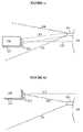
- FIGS. 1 a – 1 e Side view diagrams of a preferred embodiment for industrial applications.
- FIG. 2 A side view of a preferred embodiment for medical laser applications.
- FIG. 3 Illustration of a safety beam emitter with optical system for control of beam divergence.
- FIG. 4 Illustration of a detector with collimator or objective for control of aperture angle.
- the invention concerns a safety system that can be applied to a variety of focused energy radiation or particle sources.
- the present invention consists of an emitter-detector system.
- the safety beam emitter or emitters preferably emit low power infrared radiation, such as that used in conventional telecommands, or visible radiation typically emitted by low power lasers or photodiodes.
- the safety beam emitter or emitters are placed in or near the application or treatment area and oriented toward a preferred position of an application source.
- one or more safety beam emitters are positioned to direct a low power beam of radiation toward an application/treatment area. The radiation is reflected from the application or treatment area and is detected by the detector or detectors located at or near the output of the application source.
- the safety beam emitter is a source producing a low power beam laser.
- a monochromatic, coherent safety beam can be obtained.
- the safety beam is in the visible spectrum, so that it can be simply and easily adjusted.
- the safety beam emitter preferably incorporates an optical system, so as to control the safety beam divergence. Thereby the dimension of the safety region defined by the safety beam can be controlled.
- FIG. 3 An example of a preferred safety beam emitter according to the present invention is illustrated in FIG. 3 .
- Laser 301 is attached to holder 303 and emits safety beam 305 .
- Safety beam 305 is of a low enough power so as not to cause injury upon contact with the eye.
- An example of a preferred maximum power level is 5.0 mW.
- Safety beam 305 is directed substantially toward a preferred position of an application source (not shown).
- the divergence angle ⁇ of safety beam 305 can be controlled to expand or restrict the security space, which is defined by the divergence of safety beam 305 , with objective/collimator 307 .
- Safety beam 305 enters objective/collimator 307 and is shaped by suitable lenses 309 to create the desired divergence.
- the detector can consist of any known photodetector such as a photodiode and is preferably attached to the application laser or positioned proximate to the output port or application beam origination point.
- the photodetector is preferably coupled with a filter centered at the emission line of the monochromatic emitter, which is preferably a visible laser.
- the detector is only responsive to the signal of the safety beam emitter and not to other sources such as ambient light or the light generated by the application source.
- the detector comprises an objective or collimator, so as to control the light aperture angle.
- An example of a detector according to the present invention is shown in FIG. 4 .
- Photodiode 401 is connected to interference filter 403 centered at a desired wavelength.
- Collimator 405 is positioned to allow control of an aperture in order to be able to modify acceptance cone 407 . Adjustment of the aperture changes angle ⁇ , which defines the volume of acceptance cone 407 . The ability to modify acceptance cone 407 permits users to control the sensitivity of the detector. For example, acceptance cone 407 may be adjusted to control an acceptable level of deviation from a preferred orientation. As acceptance cone 407 is increased, the application source can be turned a larger degree away from its ideal direction before emission radiation cannot reach photodiode 401 , and vice versa.
- the system is set up so that the application beam will continue to be operable so long as the detector detects sufficient radiation from the safety beam emitter.
- a control system consisting of, for example, suitable electronics, is integrated with the detector and application beam source so that the application beam is automatically shut off or blocked if the radiation detected in the detector falls below prescribed levels.
- the term “application beam” refers to the emission path from a directionally sensitive application device, such as a laser, water drill, or particle beam source.
- the “application beam” includes, but is not limited to, a laser beam, particle beam, a water jet or water drill emission path.
- the term “application source” refers to any apparatus that emits an application beam as described above, such as a laser or particle beam source, or a water drill source.
- a decrease in the amount of radiation detected by a detector is read by the control system, which initiates a safety response in a preselected manner depending on the amount of the decrease.
- Such safety response includes alerting the user of the decrease, such as by an audible alarm, blocking the laser or other application beam or shutting off the application beam source.
- This decrease would occur for two primary reasons. In the first instance, a decrease would occur because a person or object comes close enough to the application beam so as to at least partially block the safety beam emitter radiation and thus reduces the amount of radiation incident on the detector. In the second instance, a decrease would occur because the application source is at a location or aimed in a direction such that the detectors are no longer in the path of the safety beam emitter radiation.
- the present invention can be configured through a suitable control system to automatically shut off the laser or other application source if someone or something comes too close to the application beam or if the application source is pointed away from the area of application. In this way, the present invention can effectively avoid accidental injury, particularly eye injury in the case of lasers.
- the safety beam defines a “security boundary” and “security space” which acts to restrict movement of the application source to, or exclude foreign bodies from, a specific area.
- This security space is defined by, and fills up the same volume as the safety beam.
- modifying the volume of the safety beam modifies the security space.
- the divergence of the safety beam can be modified to enlarge or restrict the security space.
- the user can move the application beam source over a larger area without appreciably changing the amount of radiation received by the detector.
- the security space is defined differently in the context of preventing people and objects from getting close to the application beam. If someone or something were to intersect the safety beam, there would be no change in the detector readings unless the person or object were close enough to also intersect the boundary formed by one or more lines extending from the safety beam emitter to the detector. In this way, a “security boundary” is defined. (See FIG. 1 ) If this security boundary is breached, the amount of radiation incident on the detector would decrease, and the control system would respond by shutting off or blocking the application source.
- an array of detectors is positioned around the emission point or output port of the application source, preferably forming a ring around the emission point.
- each detector to the safety beam emitter essentially form a cone around the majority of the application beam.
- the security boundary defines a surface area rather than a volume. Any breach of this surface area would trigger an alarm and would cause the application beam to be shut off or blocked.
- additional safety beam emitters can be positioned around the application area. The safety beams from each safety beam emitter will intersect as they propagate and diverge. In this way, a number of security surface areas can be established around the application beam, thus substantially eliminating any unprotected area around the application beam.
- the security space defines where the application source may be properly located, it also defines the permissible orientation of the application source. For example, when the application source is directed toward the safety beam emitter, the amount of radiation incident upon the detector or detectors is at a maximum. If the application source is pointed anywhere other than to the safety beam emitter, the detector reading will drop. This reading will drop gradually as the application source is pointed away from the emitter. If the application source is directed 180 degrees from its original orientation, then the radiation incident upon the detectors would be zero. The drop in the detector reading required to trigger a safety response such as an automatic shutoff can be modified to allow the user varying degrees of flexibility in the directions that an application source could be pointed.
- any decrease in intensity would trigger the shutoff, forcing the user to constantly point the application source directly at the application area.
- the shutoff would not be triggered unless there were absolutely no reading. In that case, the user could point the application source almost anywhere short of directly opposite from the application area.
- a user can therefore program the control system to shut off or block the application beam at a specific energy drop, thus restricting the direction in which the application source can be pointed as well as restricting the position of the application source.
- the security space and security boundary are defined by the safety beam emitted from the safety beam emitter toward, and reflected from the application area.
- the reflected safety beam power is detected by the detector or detectors, which are preferably attached to the application source near the source's output port, so long as the source is directed to the application area.
- the detector sends a signal to a control system that responds by alerting the user or disabling the application source to prevent an accident.
- a person or objects intersecting the security boundary formed by the safety beam would trigger a safety response as described herein.
- the control system which preferably consists of a system of electronics, can be configured to perform different functions.
- a breach of the security area, or improper application source orientation will result in a decrease in radiation incident upon the detector, which will then trigger a safety response by the control system.
- the safety response is an audible or visible alarm, alerting the user that the application source is being incorrectly aimed, or alerting a person that he or she is too close to the application beam.
- the application beam is not disabled.
- the application source is shut off completely or a device, such as a shutter for laser applications, is activated to temporarily block the application beam until the application source is correctly aimed or the obstruction is cleared.
- control system can be programmed to perform different functions depending on the amount of the decrease. For example, for a smaller decrease, an alarm is triggered to alert the user or others that the application beam is incorrectly positioned or oriented, or that there is an obstruction nearby. There is thus an opportunity to correct the condition. If the amount of radiation decreases to a further preselected level, the control system shuts off or blocks the application beam. In yet another embodiment, both an alarm is activated and the application beam is shut off or blocked. This safety system can be applied in a variety of applications including both high power and low power laser applications, as is shown in the examples described below.
- the proposed system is relatively simple and inexpensive and can increase, especially for handheld laser applications, the safety of laser medical treatments or other applications.
- the present invention is also useful for other non-laser applications, such as particle beams, or water drills.
- Other applications for which the present invention would be useful include industrial cutting and surfacing systems, especially water or laser cutting, drilling or surfacing applications.
- Development of the present invention for commercialization is also very simple, so that investments of money and time are minimized.
- the security boundary can be precisely defined by positioning the safety beam emitter and detector systems to produce a specific and highly controllable boundary. These boundaries are not defined by the divergence or volume of the safety beam, but are defined by the positions of the safety beam emitter(s) and detector(s), and thus the system is easier to manufacture, incorporate into existing treatment or application systems, and modify as needed.
- the position and orientation of the application beam can also be easily and precisely restricted with the present invention. Such precision in directing the position of the treatment/application beam is important, especially for laser medical treatments. Also, because the detector system, such as one or more photodiodes having certain filters, only absorbs the wavelengths emitted by the safety beam emitter(s), any interference with noise, such as ambient light, is minimized.
- FIGS. 1 a – 1 c illustrate a preferred embodiment of the present invention for use with high power lasers.
- safety beam emitter 101 is positioned in or near the application area, in this case industrial process area 108 .
- Safety beam emitter 101 produces a low power electromagnetic beam directed toward detectors 102 and generally directed along path 104 whose axis is parallel to high power laser application beam 105 .
- Safety beam emitter 101 is therefore located at or near the point where beam 105 intersects industrial process area 108 .
- Safety beam emitter 101 is also not necessarily located in the same plane as application beam 105 , so to avoid any contact between beam 105 and emitter 101 , if desired.
- Detector 102 can be a photodiode to which an interference filter, whose center wavelength equals that of safety beam emitter 101 , can be coupled. Detectors 102 are placed near high power laser source 106 and configured to face a direction parallel to laser 106 .
- the imaginary line extending from safety beam emitter 101 to detector 102 defines “security boundary” 107 , and is illustrated in FIGS. 1 a and 1 b . If a person or an object intersects security boundary 107 , he or it will absorb or reflect part of the signal from the safety beam emitter, and the intensity on one or more of detectors 102 will decrease.
- Simple electronic control setup 103 which is integrated with detectors 102 , realizes this signal change and causes an alarm to sound and shuts off or blocks high power laser 106 .
- the high power laser shot is disabled before the person or the object intersects laser application beam 105 and therefore avoids a possible accident.
- additional safety beam emitters 101 can be placed around process area 108 .
- detectors 102 can be placed at a greater distance from application beam source to establish a wider security boundary. An example of such a configuration is illustrated in FIG. 1 b.
- the space within beam path 104 is termed a “security space”, which is responsible for preventing a user from directing application beam 105 towards an improper location.
- the security space is illustrated in FIGS. 1 c – 1 e .
- control setup 103 will allow application beam 105 to be emitted. If laser 106 is positioned outside the security boundary, as shown in FIG. 1 d , the amount of radiation read by detectors 102 will decrease, prompting control setup 103 to sound an alarm and/or shut off or block beam 105 . Dangerous conditions may also occur if laser 106 is pointed at an improper direction, even though it is positioned within the security space.
- control setup 103 shuts off or blocks the application beam can be varied depending on the size of process area 108 and the amount of flexibility in movement of laser 106 that is desired.
- safety beam emitter 101 is located at industrial process application area 108 and directed to the proper position of high power application laser source 106 .
- the divergence angle of emitted safety beam 104 can be varied, according to the needs of the application. As seen in the above figures, if safety beam emitter 101 can be placed very close to the application area, a large divergence is not needed. However, for those applications where the laser is used over a larger area, and thus safety beam emitter 101 must be placed away from beam 105 , emitted safety beam 104 should have a greater divergence in order to protect the area around application beam 105 .
- FIG. 2 illustrates a preferred embodiment of the present invention that is particularly useful for medical applications.
- Safety beam emitter 201 is in this case a low power visible laser that is directed to medical application area 205 in a fixed position during treatment. The divergence of safety beam 206 can be controlled with the help of an optical system so as to define the dimensions of application area 205 .
- Detector 202 is a photodiode with an interference filter centered at the emission line of safety laser beam 206 and attached to fiber holder 207 . Thereby the detector is only responsive to the reflected light of safety beam emitter 201 and not to other light sources such as ambient light.
- Surgery fiber 203 is positioned within holder 207 and emits medical laser application beam 204 .
- the detector's electronic will allow use of the application source, in this case a medical laser (not shown), only if it receives a certain quantity of signal from reflected safety beam 206 of safety beam emitter 201 .
- the application source in this case a medical laser (not shown)
- detector 202 will not receive sufficient energy, and the laser will be shut off or blocked with a shutter or other mechanism.
- the operator first directs visible safety laser 201 , which is fixed to, for example, a holder, to application area 205 . Then, the divergence of safety beam 206 is modified by the operator to obtain the required security space.
- the treatment can then be performed with the application source, which is only enabled if detector 202 receives the reflected light from safety beam 206 , i.e. when application beam 204 is directed to application area 205 .
Landscapes
- Engineering & Computer Science (AREA)
- Physics & Mathematics (AREA)
- Optics & Photonics (AREA)
- Mechanical Engineering (AREA)
- Plasma & Fusion (AREA)
- Life Sciences & Earth Sciences (AREA)
- Forests & Forestry (AREA)
- Laser Surgery Devices (AREA)
- Radiation-Therapy Devices (AREA)
Abstract
Description
Claims (17)
Priority Applications (1)
| Application Number | Priority Date | Filing Date | Title |
|---|---|---|---|
| US10/712,385 US7180922B2 (en) | 2003-11-12 | 2003-11-12 | Safety system for focused energy applications |
Applications Claiming Priority (1)
| Application Number | Priority Date | Filing Date | Title |
|---|---|---|---|
| US10/712,385 US7180922B2 (en) | 2003-11-12 | 2003-11-12 | Safety system for focused energy applications |
Publications (2)
| Publication Number | Publication Date |
|---|---|
| US20050098545A1 US20050098545A1 (en) | 2005-05-12 |
| US7180922B2 true US7180922B2 (en) | 2007-02-20 |
Family
ID=34552672
Family Applications (1)
| Application Number | Title | Priority Date | Filing Date |
|---|---|---|---|
| US10/712,385 Expired - Fee Related US7180922B2 (en) | 2003-11-12 | 2003-11-12 | Safety system for focused energy applications |
Country Status (1)
| Country | Link |
|---|---|
| US (1) | US7180922B2 (en) |
Cited By (5)
| Publication number | Priority date | Publication date | Assignee | Title |
|---|---|---|---|---|
| US20070001111A1 (en) * | 2005-04-19 | 2007-01-04 | Rueb Kurt D | Method and apparatus for protecting personnel using laser projection systems |
| US20070045257A1 (en) * | 2005-08-30 | 2007-03-01 | United Technologies Corporation | Laser control system |
| US20090105698A1 (en) * | 2007-05-14 | 2009-04-23 | Ams Research Corporation | Medical Laser User Interface |
| US20090312858A1 (en) * | 2008-06-16 | 2009-12-17 | Electro Scientific Industries, Inc. | Method for defining safe zones in laser machining systems |
| US20180095168A1 (en) * | 2016-10-04 | 2018-04-05 | Sick Ag | Optoelectronic sensor and method for optical monitoring |
Families Citing this family (8)
| Publication number | Priority date | Publication date | Assignee | Title |
|---|---|---|---|---|
| US20070045250A1 (en) * | 2005-08-30 | 2007-03-01 | United Technologies Corporation | Method for manually laser welding metallic parts |
| US20070138150A1 (en) * | 2005-12-20 | 2007-06-21 | Honeywell International, Inc. | Hand-held laser welding wand position determination system and method |
| US7919723B2 (en) * | 2007-04-03 | 2011-04-05 | Renewable Thermodynamics, Llc | Apparatus and method for cutting lawns using lasers |
| FR3039287B1 (en) * | 2015-07-22 | 2020-03-27 | Arianegroup Sas | METHOD AND DEVICE FOR SECURING A SPACE CROSSED BY A HIGH POWER LASER BEAM |
| DE102017100068A1 (en) * | 2017-01-04 | 2018-07-05 | Rheinmetall Waffe Munition Gmbh | Laser system with protective device |
| DE102019102466A1 (en) * | 2019-01-31 | 2020-08-06 | Endress+Hauser Conducta Gmbh+Co. Kg | Optical sensor |
| JP2023039588A (en) * | 2021-09-09 | 2023-03-22 | 山本光学株式会社 | Measurement device and laser scattered light |
| DE102021124548A1 (en) * | 2021-09-22 | 2023-03-23 | MAX-PLANCK-Gesellschaft zur Förderung der Wissenschaften e.V. | Safety device and method for monitoring a light path of a laser beam and their applications |
Citations (6)
| Publication number | Priority date | Publication date | Assignee | Title |
|---|---|---|---|---|
| US4687918A (en) | 1985-05-03 | 1987-08-18 | Hughes Technology Pty Ltd | Safe laser pointers with remote directional activation |
| US4884275A (en) | 1988-10-24 | 1989-11-28 | Murasa International | Laser safety shutoff system |
| US5117221A (en) | 1990-08-16 | 1992-05-26 | Bright Technologies, Inc. | Laser image projection system with safety means |
| US5301347A (en) | 1991-10-30 | 1994-04-05 | The United States Of America As Represented By The Secretary Of The Air Force | Multi-system laser safety shutter controller |
| US6130754A (en) | 1995-12-07 | 2000-10-10 | Electro Optic Systems Pty. Limited | Eyesafe transmission of hazardous laser beams |
| US6771678B1 (en) * | 2000-06-13 | 2004-08-03 | International Business Machines Corporation | Laser system and method of operation having improved signal continuity and safety |
-
2003
- 2003-11-12 US US10/712,385 patent/US7180922B2/en not_active Expired - Fee Related
Patent Citations (6)
| Publication number | Priority date | Publication date | Assignee | Title |
|---|---|---|---|---|
| US4687918A (en) | 1985-05-03 | 1987-08-18 | Hughes Technology Pty Ltd | Safe laser pointers with remote directional activation |
| US4884275A (en) | 1988-10-24 | 1989-11-28 | Murasa International | Laser safety shutoff system |
| US5117221A (en) | 1990-08-16 | 1992-05-26 | Bright Technologies, Inc. | Laser image projection system with safety means |
| US5301347A (en) | 1991-10-30 | 1994-04-05 | The United States Of America As Represented By The Secretary Of The Air Force | Multi-system laser safety shutter controller |
| US6130754A (en) | 1995-12-07 | 2000-10-10 | Electro Optic Systems Pty. Limited | Eyesafe transmission of hazardous laser beams |
| US6771678B1 (en) * | 2000-06-13 | 2004-08-03 | International Business Machines Corporation | Laser system and method of operation having improved signal continuity and safety |
Cited By (8)
| Publication number | Priority date | Publication date | Assignee | Title |
|---|---|---|---|---|
| US20070001111A1 (en) * | 2005-04-19 | 2007-01-04 | Rueb Kurt D | Method and apparatus for protecting personnel using laser projection systems |
| US20070045257A1 (en) * | 2005-08-30 | 2007-03-01 | United Technologies Corporation | Laser control system |
| US20090105698A1 (en) * | 2007-05-14 | 2009-04-23 | Ams Research Corporation | Medical Laser User Interface |
| US9486286B2 (en) * | 2007-05-14 | 2016-11-08 | Boston Scientific Scimed, Inc. | Medical laser user interface |
| US10383690B2 (en) | 2007-05-14 | 2019-08-20 | Boston Scientific Scimed, Inc. | Medical laser user interface |
| US20090312858A1 (en) * | 2008-06-16 | 2009-12-17 | Electro Scientific Industries, Inc. | Method for defining safe zones in laser machining systems |
| US8024060B2 (en) * | 2008-06-16 | 2011-09-20 | Electro Scientific Industries, Inc. | Method for defining safe zones in laser machining systems |
| US20180095168A1 (en) * | 2016-10-04 | 2018-04-05 | Sick Ag | Optoelectronic sensor and method for optical monitoring |
Also Published As
| Publication number | Publication date |
|---|---|
| US20050098545A1 (en) | 2005-05-12 |
Similar Documents
| Publication | Publication Date | Title |
|---|---|---|
| US7180922B2 (en) | Safety system for focused energy applications | |
| EP2707701B1 (en) | Optical hazard avoidance device and method | |
| US20210033747A1 (en) | Light curtain safety system | |
| US8203698B2 (en) | Control modules for laser systems having auto-ranging and control capability | |
| US20080044178A1 (en) | Laser safety system | |
| CN105682599B (en) | Skin-treatment device for the skin treatment based on multi-photon | |
| US7834302B2 (en) | Eye safety protection from high power laser light | |
| US20090219961A1 (en) | Laser Systems and Methods Having Auto-Ranging and Control Capability | |
| US7110825B2 (en) | Method, a system, and a device for detecting and for reducing energy leakage from an energy treatment devices | |
| WO2002076319A1 (en) | Method and apparatus for monitoring laser surgery | |
| JP2008512201A (en) | Replaceable tip for medical laser treatment and use of the tip | |
| US10470843B2 (en) | Systems and methods for alignment of a laser beam | |
| JPS631054B2 (en) | ||
| KR101809547B1 (en) | Laser apparatus for medical and method to control thereof | |
| US20170373454A1 (en) | Laser Safety Device | |
| KR101301878B1 (en) | Visible Laser which can controlling nominal ocular hazard distance | |
| KR20150005313A (en) | Infra-red Laser Device for inspection | |
| Paulausky | Laser safety: the eyes have it | |
| KR20080105862A (en) | Laser cleaning device | |
| WO2001019454A2 (en) | Laser apparatus with power stabilising and deflection system | |
| JPH03146050A (en) | Laser medical treatment device |
Legal Events
| Date | Code | Title | Description |
|---|---|---|---|
| AS | Assignment |
Owner name: CERAMOPTEC INDUSTRIES, INC., MASSACHUSETTS Free format text: ASSIGNMENT OF ASSIGNORS INTEREST;ASSIGNOR:DE LA CAL, EDUARDO;REEL/FRAME:014707/0420 Effective date: 20031013 |
|
| FPAY | Fee payment |
Year of fee payment: 4 |
|
| AS | Assignment |
Owner name: BIOLITEC PHARMA MARKETING LTD., MALAYSIA Free format text: ASSIGNMENT OF ASSIGNORS INTEREST;ASSIGNOR:CERAMOPTEC INDUSTRIES, INC.;REEL/FRAME:030245/0215 Effective date: 20130315 |
|
| REMI | Maintenance fee reminder mailed | ||
| LAPS | Lapse for failure to pay maintenance fees | ||
| STCH | Information on status: patent discontinuation |
Free format text: PATENT EXPIRED DUE TO NONPAYMENT OF MAINTENANCE FEES UNDER 37 CFR 1.362 |
|
| STCH | Information on status: patent discontinuation |
Free format text: PATENT EXPIRED DUE TO NONPAYMENT OF MAINTENANCE FEES UNDER 37 CFR 1.362 |
|
| FP | Lapsed due to failure to pay maintenance fee |
Effective date: 20150220 |
|
| AS | Assignment |
Owner name: BIOLITEC UNTERNEHMENSBETEILIGUNGS II AG, AUSTRIA Free format text: ASSIGNMENT OF ASSIGNORS INTEREST;ASSIGNOR:BIOLITEC PHARMA MARKETING LTD.;REEL/FRAME:041182/0578 Effective date: 20160308 |