US7167847B2 - DNA computer and a computation method using the same - Google Patents
DNA computer and a computation method using the same Download PDFInfo
- Publication number
- US7167847B2 US7167847B2 US11/064,027 US6402705A US7167847B2 US 7167847 B2 US7167847 B2 US 7167847B2 US 6402705 A US6402705 A US 6402705A US 7167847 B2 US7167847 B2 US 7167847B2
- Authority
- US
- United States
- Prior art keywords
- solution
- dna
- partial
- computer
- dna computer
- Prior art date
- Legal status (The legal status is an assumption and is not a legal conclusion. Google has not performed a legal analysis and makes no representation as to the accuracy of the status listed.)
- Expired - Fee Related, expires
Links
Images


Classifications
-
- G—PHYSICS
- G06—COMPUTING OR CALCULATING; COUNTING
- G06N—COMPUTING ARRANGEMENTS BASED ON SPECIFIC COMPUTATIONAL MODELS
- G06N3/00—Computing arrangements based on biological models
- G06N3/12—Computing arrangements based on biological models using genetic models
- G06N3/123—DNA computing
-
- B—PERFORMING OPERATIONS; TRANSPORTING
- B82—NANOTECHNOLOGY
- B82Y—SPECIFIC USES OR APPLICATIONS OF NANOSTRUCTURES; MEASUREMENT OR ANALYSIS OF NANOSTRUCTURES; MANUFACTURE OR TREATMENT OF NANOSTRUCTURES
- B82Y10/00—Nanotechnology for information processing, storage or transmission, e.g. quantum computing or single electron logic
Definitions
- the present invention generally relates to DNA computers and computation methods using the same, and more particularly to a DNA computer suited for complex computations and a computation method using such a DNA computer.
- the DNA computer solves, at a high speed, a satisfiability (SAT) problem or the like having an extremely large solution search space, using molecular reaction.
- the hardware of the DNA computer is formed by molecules called nucleotides forming the DNA.
- a nucleotide sequence of the DNA obtained by subjecting the DNA to a basic operation of the DNA computer becomes the output of the DNA computer.
- the nucleotide sequence of the DNA representing the output of the DNA computer is amplified using a Polymerase Chain Reaction (PCR) that creates a large amount of copies of the nucleotide sequence. It is possible read the output of the DNA computer by determining the nucleotide sequence of the DNA by electrophoresis using differences in molecular weights of the nucleotides.
- PCR Polymerase Chain Reaction
- the genetic algorithm is a technique that simulates genetic mechanisms of organisms for application to engineering, as described in D. Goldberg, “Genetic Algorithms in Search, Optimization, and Machine Learning”, Addison-Wesley, 1989, for example.
- FIG. 1 is a diagram showing examples of the generations in the genetic algorithm.
- a target function of the satisfiability problem corresponds to the environment, and a fitness function that takes a larger value as the target function becomes more optimized is defined with respect to the chromosome.
- the selection (or reproduction) is an operation of selecting with a higher probability the individual with the chromosome having a high fitness in the group so that the selected individual becomes the parent of the next generation.
- FIG. 2 is a diagram showing an example of the selection in the genetic algorithm.
- the crossover is an operation of creating a new individual (child) by interchanging portions of 2 chromosomes (parents).
- FIG. 3 is a diagram showing an example of the crossover of the genetic algorithm.
- the mutation is an operation of randomly replacing the genes of a portion of 1 chromosome.
- FIG. 4 is a diagram showing an example of the mutation in the genetic algorithm.
- the chromosome having a high fitness that is, the solution which optimizes the target function, is obtained.
- FIG. 5 is a flow chart showing an example of a computation process of the DNA computer.
- a step S 1 encodes a problem that is to be solved by the computation process into DNAs.
- a step S 2 carries out a hybridization so as to create a sufficient amount of DNAs as solution candidates.
- a step S 3 carries out a screening of the solution candidates by the DNA computer, so as to select a solution from the solution candidates.
- the DNA is formed by deoxyribonucleic acid.
- the deoxyribonucleic acid is formed by nucleotides.
- the nucleotide is formed by sugar, phosphorylation and base.
- the sugar and phosphorylation are common to the deoxyribonucleic acid, but 4 kinds of bases exist depending on the base, namely, adenine (A), guanine (G), cytosine (C) and thymine (T).
- A adenine
- G guanine
- C cytosine
- T thymine
- the 5′ phosphorylzation of the nucleotide and the 3′ hydroxyl group bond to form a kind of covalent bond (phosphodiester bond).
- the new nucleotide is added to the 3′ determinal of the DNA.
- the base portion of the nucleotide bonds to the base portion of another nucleotide by hydrogen bond.
- the bonding element that bonds to the base portion of the nucleotide is restricted, and the base pair may be formed by A and T or, by G and C, due to complementation.
- FIG. 6 is a diagram showing an example of the encoding of the solution candidates for a case where an effective Hamiltonian path problem is solved.
- Such an encoding of the solution candidates is described in Hagitani et al., “DNA Computer”, Baifukan, pp. 137–143, 2001, for example.
- the solution candidates for the problem that are encoded in this manner are fed to a test tube S containing a solution (or liquid), so that basic operations which will be described later are carried out.
- the basic operations include 5 operations, namely, “amplify”, “merge”, “get”, “append” and “detect”.
- the basic operations themselves are described in A. Toyama, “Experiments in Molecular Computer”, Risukagaku, (445), pp. 24–31, 2000, for example.
- the “amplify” operation creates a copy of what is within the test tube S containing the DNA.
- the “get” operation gets from the test tube S the DNA satisfying (or not satisfying) a condition described by a code sequence of the nucleotides A, T, G and C and feeds this DNA to another test tube.
- the “append” operation appends a specified nucleotide sequence if the terminal of the DNA molecule in the test tube S satisfies a certain condition.
- the “detect” operation returns a “true” if the test tube S contains at least 1 DNA, and otherwise returns a “false”, with respect to the test tube S.
- the DNA computer combines the 5 operations described above depending on the problem to be solved, and obtain the solution from the solution candidates of the initially prepared DNAs.
- Such a computation method of the DNA computer is described in Leonard M. Adleman, “Molecular computation of solutions to combinational problems”, SCIENCE, 266 (5187), pp. 1021–1024, 1994, for example, and are often referred to as the “Adleman paradigm”.
- FIG. 7 is a diagram showing an example of the screening for a case where the effective Hamiltonian path problem is solved.
- S 11 denotes a problem encoding stage
- S 2 denotes a hybridization stage
- S 13 denotes a screening stage.
- Another and more specific object of the present invention is to provide a DNA computer and a computation method using the DNA computer, which can easily carry out a computation process without increasing the amount of DNAs that are required even when the computation becomes complex, and can carry out an accurate computation process by suppressing the error generation rate of the solution by carrying out the computation process in a relatively small number of computation steps.
- Still another object of the present invention is to provide a DNA computer for carrying out computations using DNAs, comprising a dividing part configured to divide a problem that is to be solved into a plurality of partial problems; and an operation part configured to obtain a DNA sequence corresponding to a solution to the problem, by combining DNA sequences corresponding to solutions of the plurality of partial problems.
- a DNA computer for carrying out computations using DNAs, comprising a dividing part configured to divide a problem that is to be solved into a plurality of partial problems; and an operation part configured to obtain a DNA sequence corresponding to a solution to the problem, by combining DNA sequences corresponding to solutions of the plurality of partial problems.
- a further object of the present invention is to provide a computation method using a DNA computer that carries out computations using DNAs, comprising a dividing step dividing a problem that is to be solved into a plurality of partial problems; and an operation step obtaining a DNA sequence corresponding to a solution to the problem, by combining DNA sequences corresponding to solutions of the plurality of partial problems.
- the DNA computer of the present invention it is possible to easily carry out a computation process without increasing the amount of DNAs that are required even when the computation becomes complex, and carry out an accurate computation process by suppressing the error generation rate of the solution by carrying out the computation process in a relatively small number of computation steps.
- FIG. 1 is a diagram showing examples of the generations in the genetic algorithm
- FIG. 2 is a diagram showing an example of the selection in the genetic algorithm
- FIG. 3 is a diagram showing an example of the crossover in the genetic algorithm
- FIG. 4 is a diagram showing an example of the mutation in the genetic algorithm
- FIG. 5 is a flow chart showing an example of a computation process of a DNA computer
- FIG. 6 is a diagram showing an example of encoding solution candidates for a case where an effective Hamiltonian path problem is solved
- FIG. 7 is a diagram showing an example of a screening for a case where the effective Hamiltonian path problem is solved.
- FIG. 8 is a system block diagram showing a structure of a DNA computer
- FIG. 9 is a diagram for explaining a case where a problem is divided into partial problems according to a serial division method
- FIG. 10 is a diagram for explaining the operation of the DNA computer for the case where the problem is divisible into the partial problems by the serial division method;
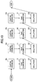
- FIG. 11 is a diagram for explaining a case where a problem is divided into partial problems according to a layered network division method
- FIG. 12 is a diagram for explaining the operation of the DNA computer for the case where the problem is divisible into the partial problems by the layered network division method;
- FIG. 13 is a diagram for explaining a control of the DNA computer by the genetic algorithm
- FIG. 14 is a flow chart for explaining the control of the DNA computer by the genetic algorithm
- FIG. 15 is a diagram showing a relationship of a length and a GC content of oligonucleotides (DNA fragments) that are combined;
- FIG. 16 is a diagram for explaining solution candidates that are created from a restricted solution candidate D 0 using an evolution technique
- FIG. 17 is a diagram for explaining solution candidates that are created from a restricted solution candidate D 1 using the evolution technique
- FIG. 18 a diagram for explaining solution candidates that are created from a restricted solution candidate D 2 using the evolution technique
- FIG. 19 a diagram for explaining solution candidates that are created from a restricted solution candidate D 3 using the evolution technique
- FIG. 20 a diagram for explaining solution candidates that are created from a restricted solution candidate D 4 using the evolution technique
- FIG. 21 is a flow chart for explaining a method of omitting unnecessary operations using the evolution technique
- FIG. 22 is a flow chart for explaining a technique that increases the computation speed by referring to previous computation results using the evolution technique
- FIG. 23 is a diagram for explaining a GC content of solution candidates
- FIG. 24 is diagram showing an effective graph that indicates an effective Hamiltonian path problem
- FIG. 25 is a diagram showing partial problems of the problem shown in FIG. 24 ;
- FIG. 26 is a diagram showing partial problems including the partial problems shown in FIG. 25 ;
- FIG. 27 is a diagram showing partial problems including the partial problems shown in FIG. 26 ;
- FIG. 28 is a diagram showing partial problems including the partial problems shown in FIG. 27 ;
- FIG. 29 is a diagram showing partial problems including the partial problems shown in FIG. 28 ;
- FIG. 30 is a diagram for explaining an encoding scheme for nodes of the effective Hamiltonian path problem.
- FIG. 31 is a diagram for explaining an encoding scheme for effective sides of the effective Hamiltonian path problem.
- Organisms possess genetic information that are acquired during the evolution process without dumping the accumulated genetic information. For this reason, DNA sequences of genes related to segmental structures of the organisms are similar for various ranges of species. As prokaryotes evolved to eucaryotes, and unicellular organisms evolved to mammals, one reason for the increase in the length of the DNA sequence is the accumulation of the genetic information (Takashi Miyata, “Divergence Pattern of Animal Gene Families and Relationship with the Cambrian Explosion”, Nikkei Science (in Japanese), March 2004). If the genetic information is regarded as a solution to a problem, the DNA of the organism may be interpreted as a collection of solutions to the problems solved during the evolution. The ultimate problem the organism itself intends to solve is presently unknown except for the self-reproduction, but the DNA computer can solve a problem using such an evolution process.
- this embodiment regards the problem that is to be solved by the DNA computer as being made up of partial problems, and the solution to the entire problem is obtained by combining the solutions to the partial problems.
- An encoding scheme for encoding the problem that is to be solved by the computation process into the DNAs uses a combination of 1 variable xi and 4 kinds of nucleotides (adenine (A), guanine (G), cytosine (C) and thymine (T)) of the DNA representing the values of the variable xi.
- the problem that is to be solved is encoded into a nucleotide sequence representing the variable xi and a nucleotide sequence representing the value (for example, “true” or “false”) of the variable xi.
- the solution candidates for the problem that is encoded in this manner are fed to a test tube S containing a solution (or liquid), wherein basic operations are carried out.
- the basic operations include the 5 operations, namely, “amplify”, “merge”, “get”, “append” and “detect”.
- the “amplify” operation is represented by amplify (S, S 1 , . . . , Si, . . . ), and amplifies a partial set of DNAs satisfying a certain condition, of the DNAs within the test tube S, and feeds the partial set of DNAs satisfying the certain condition to another test tube Si.
- the “detect” operation confirms whether or not the test tube S contains DNAs. That is, the “detect” operation returns a “true” if the test tube S contains at least 1 DNA, and otherwise returns a “false”.
- the DNA computer combines the 5 operations described above depending on the problem that is to be solved, so as to obtain the solution from the solution candidates of the initially prepared DNAs.
- this embodiment employs the evolution technique that similarly represents the solution to the partial problem by a one-dimensional sequence, and obtains the solution or the solution candidate for the original problem by combining the solutions to the partial problems and searching for the solution to the original problem.
- FIG. 8 is a system block diagram showing a structure of a DNA computer 11 .
- a DNA molecular chemical reaction part 1 is formed by a test tube containing DNAs within a solution (or liquid).
- a chemical reaction control part 2 supplies enzymes, primers (DNA fragments) or the like to the DNA molecular chemical reaction part 1 .
- a DNA encoding part 3 prepares the DNAs necessary for the setup of the DNA computer 11 .
- a DNA computer control part 4 is formed by a general purpose computer, and store a program that utilizes the basic operations of the DNA computer 11 .
- the DNA computer control part 4 instructs operations to the chemical reaction control part 2 and the DNA molecular chemical reaction part 1 .
- a detecting part 5 includes an apparatus for reading an output (DNA sequence) of the DNA computer 11 by electrophoresis or the like.
- the evolution technique is applied to the DNA computer 11 shown in FIG. 8 , so as to store the solution to the partial problem as a corresponding nucleotide sequence, and to use the nucleotide sequence when solving the next partial problem.
- a judgement is made by computer simulation to determine whether or not there is a possibility that the solution to the partial problem becomes a portion of the solution to the original problem, and the operations of the DNA computer 11 are carried out if the possibility exists, while the operations of the DNA computer 11 are not carried out if the possibility does not exist.
- a solution to a partial problem which is one prior to the solution to the partial problem that has become known to finally fail as a result of the computer simulation, is not dumped but is stored.
- the solution to the partial problem that is stored in this manner may be utilized when obtaining a solution to another partial problem, so that the solution may be obtained efficiently.
- a restricted solution candidate that is, a solution candidate with a restriction
- Ck for a partial problem Pk is defined as a case where “Ck is a solution to the partial problem Pk” or “it cannot be explicitly shown that Ck is not a portion of the solution to the problem P (that is, there is a possibility that Ck is a portion of the solution to the problem P)”.
- Ck+1 includes Ck when an arbitrary restricted solution candidate Ck to the partial problem Pk is a portion of a restricted solution candidate Ck+1 to a partial problem Pk+1, and that the partial problem Pk+1 includes the partial problem Pk in this case.
- a solution candidate ⁇ k+1 (not necessarily a restricted solution candidate) for the partial problem Pk does not become a solution to the problem P
- a technique which creates a solution that is different from the solution candidate ⁇ k+1 from the restricted solution candidate Ck for the partial problem Pk which is one prior to the partial problem Pk+1, and finds a restricted solution candidate for the partial problem Pk+1 may be employed. In this case, it is possible to improve the computation efficiency of the DNA computer 11 .
- the solution to the problem P satisfying the restricting conditions of the problem P is selected from the restricted solution candidates that are obtained by solving the partial problems P 1 , P 2 , . . . , PN in this order.
- solution candidates are all prepared in advance, and the solution is selected from the solution candidates so as to reduce the computation time.
- the total number of solution candidates is extremely large, thereby making this solving technique unrealistic.
- the partial problems are sequentially solved by the DNA computer 11 , so as to realize a realistic solving technique for the large-scale problem.
- the algorithms of the DNA computer 11 that are applicable when the problem is divisible into the partial problems include a serial division technique and a layered network division method which will be described later.
- FIG. 9 is a diagram for explaining a case where a problem is divided into partial problems according to the serial division method. For the sake of convenience, FIG. 9 shows a case where the original problem P is divided into 4 partial problems P 1 through P 4 and connected by arcs forming the graph.
- FIG. 10 is a diagram for explaining the operation of the DNA computer 11 for the case where the problem is divisible into the partial problems by the serial division method.
- the partial problem P 1 is solved by the DNA computer 11 , and a solution C 1 is fed back to the DNA computer 11 .
- the partial problem P 2 is solved by the DNA computer 11 using the solution C 1 , and a solution C 2 is fed back to the DNA computer 11 .
- the operations are carried out similarly thereafter, and when a solution C 4 is output from the DNA computer 11 , the operations end.
- the solution to the partial problem P 1 can be represented by a nucleotide sequence C 1 .
- a marker is added to the 3′ terminal of the nucleotide sequence C 1 to indicate that this solution is a solution to the partial problem P 1 .
- a nucleotide sequence C 2 which is the solution to the partial problem P 2 is bonded to the nucleotide sequence C 1 .
- a marker is added to the 3′ terminal of the nucleotide sequence C 2 to indicate that this solution is a solution to the partial problem P 2 , and similar operations are repeated thereafter.
- nucleotide sequence representing the solution may be arranged at a center portion, and the nucleotide sequence indicating the partial problem may be arranged on both sides thereof.
- nucleotide sequence representing the partial problems it is possible to use a combination of the nucleotide sequences representing the partial problems as a primer.
- the order in which the partial problems are solved may be switched or interchanged.
- the problem may be divided into the partial problems according to order of solving ease, so that the solution can be obtained within a short time.
- FIG. 11 is a diagram for explaining a case where a problem is divided into partial problems according to the layered network division method.
- FIG. 11 shows a case where the original problem P is segmented (or divided) into a graph in which the 4 partial problems P 1 through P 4 are connected by arcs, a graph in which 4 partial problems P 5 through P 8 are connected by arcs, and a graph in which 4 partial problems P 9 through P 12 are connected by arcs.
- the layered network shown in FIG. 12 consists of 3 layers.
- FIG. 12 is a diagram for explaining the operation of the DNA computer for the case where the problem is divisible into the partial problems by the layered network division method.
- the partial problem P 1 is solved by the DNA computer 11 , and a solution C 1 is fed back to the DNA computer 11 .
- the partial problem P 2 is solved by the DNA computer 11 using the solution C 1 , and a solution C 2 is fed back to the DNA computer 11 .
- the operations are carried out similarly thereafter with respect to the partial problems P 3 and P 4 , and a solution C 4 is output from the DNA computer 11 and fed back to the DNA computer 11 .
- the operations with respect to the partial problems P 5 through P 8 are carried out in parallel with the operations with respect to the partial problems P 1 through P 4 , and similarly to the operations with respect to the partial problems P 1 through P 4 , such that a solution C 8 is output from the DNA computer 11 and fed back to the DNA computer 11 .
- the operations with respect to the partial problems P 9 through P 12 are also carried out in parallel with the operations with respect to the partial problems P 1 through P 4 , and also similarly to the operations with respect to the partial problems P 1 through P 4 , such that a solution C 12 is output from the DNA computer 11 and fed back to the DNA computer 11 .
- the operations end when the solutions C 4 , C 8 and C 12 are output from the DNA computer 11 and fed back to the DNA computer 11 .
- DNAs corresponding to the solution to the partial problem (generally, solutions to a plurality of partial problems) solved in the layer which is one prior to the certain layer are mixed.
- solutions to a plurality of partial problems solved in the layer which is one prior to the certain layer are mixed.
- the solution candidates By combining such solutions similarly as in the case of the serial division method, it is possible to obtain the solution candidates.
- the DNAs representing the solutions to the partial problems corresponding to the nodes of the final layer are collected and fed to the same test tube, and the solution is selected from the solution candidates within the test tube.
- nucleotide sequence representing the solution to the partial problem may be arranged at the center portion, and the nucleotide sequence indicating the partial problem and the layer within the layered network may be arranged on both sides thereof.
- nucleotide sequence representing the solution to the problem may be synthesized from the nucleotide sequences representing the solutions to the partial problems, it is possible to use a combination of the nucleotide sequences representing the partial problems as a primer.
- the order of the layers within the layered network may be switched or interchanged.
- the order of the layers corresponds to the chromosome.
- a fitness f of the chromosome of the genetic algorithm is computed based on an error generation rate ER of the final solution to the problem, and are defined by one of the following formulas (1) through (3), where CR denotes a correct rate of the solution, W 1 through W 4 denote weighting coefficients, CV 1 and CV 2 denote constants, CT denotes a computation time required by the DNA computer 11 to compute the solution, and MQ denotes a DNA molecular weight required for the DNA computer 11 to compute the solution.
- f W 1 ⁇ (100 ⁇ ER )+ W 2 ⁇ ( CV 1 ⁇ CT ) (2)
- f W 3 ⁇ (100 ⁇ ER )+ W 4 ⁇ ( CV 2 ⁇ MQ ) (3)
- the formula (1) computes the fitness f based on the error generation rate ER of the final solution.
- the formula (2) computes the fitness f based on the error generation rate ER of the final solution and the computation time CT required by the DNA computer 11 to compute the solution.
- the formula (3) computes the fitness f based on the error generation rate ER of the final solution and the DNA molecular weight MQ required for the DNA computer 11 to compute the solution.
- the fitness f may also be obtained from an average value of 2 or more fitness values that are computed using the formulas (1) through (3).
- FIG. 13 is a diagram for explaining a control of the DNA computer by the genetic algorithm.
- the fitness is f 1 when solving the partial problems P 1 and P 2 in this order, and the fitness is f 2 when solving the problems P 2 and P 1 in this order.
- the fitness is f 3 when solving the partial problems P 11 and P 12 in this order.
- the Partially Matched Crossover (PMX) is used for the crossover of the chromosomes.
- the PMX is a crossover technique that forms child chromosomes without paradox, based on the mapping of genes in the regions of the chromosomes that are the subject of the crossover. But since there are restrictions to the order in which the partial problems are solved, no child is created if the child chromosome does not satisfy the restrictions.
- the region of the chromosome including a partial problem that requires a long computation time CT for the DNA computer 11 to compute the solution or, a partial problem that requires a large DNA molecular weight MQ for the DNA computer 11 to compute the solution, may be selected as the subject of the crossover, so as to effectively decrease the fitness f.
- the mutation transforms 2 genes at a predetermined probability.
- the mutation since there are restrictions to the order in which the partial problems are solved, the mutation is prohibited if the mutation does not satisfy the restrictions.
- the region of the chromosome including a partial problem that requires a long computation time CT for the DNA computer 11 to compute the solution or, a partial problem that requires a large DNA molecular weight MQ for the DNA computer 11 to compute the solution may be selected as the region in which the mutation is to occur, so as to effectively increase the fitness f by the mutation.
- FIG. 14 is a flow chart for explaining the control of the DNA computer by the genetic algorithm.
- steps S 21 through S 28 are carried out by a general purpose computer
- steps S 31 through S 37 are carried out by the DNA computer 11 .
- the step S 21 shown in FIG. 14 divides a problem that is to be solved into partial problems such as those described above.
- the step S 22 sets the order in which the partial problems are to be solved at random, and creates an initial group of solution candidates by the genetic algorithm (GA).
- the step S 23 carries out a crossover operation with respect to the initial group.
- the step S 24 carries out a mutation operation with respect to the initial group, and the step S 25 supplies to the DNA computer 11 the order in which the partial problems is to be solved.
- the step S 26 computes the fitness f based on information related to the correct rate CR of the solution and the like received from the DNA computer 11 .
- the step S 27 selects an order in which the partial problems are to be solved, that minimizes the error generation rate ER of the solution obtained by the DNA computer 11 , based on the fitness f, of the orders in which the partial problems may be solved.
- the step S 28 judges whether or not the solutions to the partial problems solved in the selected order satisfy a certain reference (restriction), and the process returns to the step S 23 if the judgement result in the step S 28 is NO.
- the process of the general purpose computer ends if the judgement result in the step S 28 is YES.
- the step S 31 computes the partial problems represented by the chromosome of each individual in the partial problem solving order received from the step S 25 .
- the step S 33 obtains the solution to the k-th partial problem.
- the step S 34 combines the DNA representing the solution to the k-th partial problem with the DNA representing the solution to the (k ⁇ 1)-th partial problem if it exists.
- the step S 36 judges whether or not the solutions to all of the partial problems have been computed, and the process returns to the step S 33 if the judgement result in the step S 36 is NO.
- the step S 37 computes the information that is required to compute the fitness f, such as the correction rate CR of the solution (or the error generation rate ER), the computation time CT and the DNA molecular weight MQ, based on the formulas (1) through (3) described above, and supplies the computed information to the general purpose computer. More particularly, the step S 37 supplies the information required to compute the fitness f to the step S 26 .
- FIG. 15 is a diagram showing a relationship of the length and the GC content of the oligonucleotides (DNA fragments) that are combined.
- the partial problems P 1 through P 3 are defined as follows.
- the partial problem P 1 is to “create a DNA by 1 oligonucleotide having a length of 9 bases or less”.
- the partial problem P 2 is to “create a DNA by 2 oligonucleotides having a length of 9 bases or less”.
- the partial problem P 3 is to “create a DNA by 3 oligonucleotides having a length of 9 bases or less”.
- the restricted solution candidates are the DNAs having the length of 9 bases or less.
- oligonucleotides DNA fragments
- D 0 , D 1 , D 2 , D 3 and D 4 5 kinds of oligonucleotides (DNA fragments) D 0 , D 1 , D 2 , D 3 and D 4 exist within the test tube.
- the oligonucleotides D 0 , D 1 , D 2 , D 3 and D 4 each have a length of 9 bases or less, and as may be seen from FIGS. 16 through 20 , these oligonucleotides D 0 , D 1 , D 2 , D 3 and D 4 are restricted solution candidates for the partial problem P 1 .
- FIG. 16 is a diagram for explaining the restricted solution candidates that are created from the restricted solution candidate D 0 using the evolution technique.
- FIG. 17 is a diagram for explaining the restricted solution candidates that are created from the restricted solution candidate D 1 using the evolution technique.
- FIG. 18 a diagram for explaining the restricted solution candidates that are created from the restricted solution candidate D 2 using the evolution technique.
- FIG. 19 a diagram for explaining the restricted solution candidates that are created from the restricted solution candidate D 3 using the evolution technique.
- FIG. 20 a diagram for explaining the restricted solution candidates that are created from the restricted solution candidate D 4 using the evolution technique.
- the DNAs marked “X” are not restricted solution candidates and thus, the actual DNAs are not created for such.
- the numerals in brackets shown near each restricted solution candidate indicate the length of the base sequence of the restricted solution candidate by the first numeral, and the GC content (in arbitrary units) of the restricted solution candidate by the second numeral.
- the restricted solution candidates for the partial problem P 2 are obtained using the restricted solution candidates D 0 , D 1 , D 2 , D 3 and D 4 for the partial problem P 1 .
- oligonucleotides D 0 -D 1 , D 0 -D 2 , D 0 -D 3 and D 0 -D 4 obtained by adding oligonucleotides D 1 , D 2 , D 3 and D 4 to the oligonucleotide (DNA fragment) D 0 are considered.
- the lengths of the oligonucleotides D 0 -D 1 , D 0 -D 2 , D 0 -D 3 and D 0 -D 4 respectively are 6, 7, 9 and 8 bases, and the GC contents of the oligonucleotides D 0 -D 1 , D 0 -D 2 , D 0 -D 3 and D 0 -D 4 respectively are 37, 40, 49 and 44.
- the DNA computer 11 is actually operated to create the corresponding DNAs. As may be seen from FIG.
- oligonucleotides D 1 -D 2 , D 1 -D 3 , D 1 -D 4 and D 1 -D 0 obtained by adding oligonucleotides D 2 , D 3 , D 4 and D 0 to the oligonucleotide D 1 ;
- oligonucleotides D 2 -D 3 , D 2 -D 4 , D 2 -D 0 and D 2 -D 1 obtained by adding oligonucleotides D 3 , D 4 , D 0 and D 1 to the oligonucleotide D 2 ;
- oligonucleotides D 3 -D 4 , D 3 -D 0 , D 3 -D 1 and D 3 -D 2 obtained by adding oligonucleotides D 4 , D 0 , D 1 and D 2 to the oligonucleotide D 3 ;
- oligonucleotides D 4 -D 0 obtained by
- the restricted solution candidates for the partial problem P 3 are obtained using the restricted solution candidates for the partial problem P 2 .
- an oligonucleotide D 0 -D 1 -D 2 obtained by adding the oligonucleotide D 2 to the oligonucleotide D 0 -D 1 is considered. Since the oligonucleotide D 0 -D 1 -D 2 has a length of 9 bases or less and is a restricted solution candidate, the DNA computer 11 is actually operated to create the corresponding DNA.
- an oligonucleotide D 0 -D 1 -D 3 obtained by adding the oligonucleotide D 3 to the oligonucleotide D 0 -D 1 is considered. Since the oligonucleotide D 0 -D 1 -D 3 has a length of 11 bases which is not 9 bases or less and is not a restricted solution candidate, the DNA computer 11 is not actually operated and no corresponding DNA is created. No corresponding DNA is created for an oligonucleotide D 0 -D 1 -D 4 that is obtained by adding the oligonucleotide D 4 to the oligonucleotide D 0 -D 1 , for similar reasons.
- FIG. 21 is a flow chart for explaining a method of omitting unnecessary operations using the evolution technique.
- a step S 41 judges whether or not the length of the resulting oligonucleotide exceeds 9 bases if the oligonucleotide D 3 is added to the oligonucleotide D 0 -D 1 . If the judgement result in the step S 41 is NO, it is judged that the resulting oligonucleotide D 0 -D 1 -D 3 is a restricted solution candidate since its length is 9 bases or less.
- a step S 42 judges that the resulting oligonucleotide D 0 -D 1 -D 3 is not a restricted solution candidate.
- a step S 43 does not carry out the operations by the DNA computer 11 since the operations will fail with respect to the resulting oligonucleotide D 0 -D 1 -D 3 .
- an oligonucleotide D 0 -D 2 -D 1 obtained by adding the oligonucleotide D 1 to the oligonucleotide D 0 -D 2 is considered. Since the oligonucleotide D 0 -D 2 -D 1 has a length of 9 bases and is a restricted solution candidate, the DNA computer 11 is actually operated to create the corresponding DNA.
- the length of the oligonucleotide D 0 -D 3 is already 9 bases, and thus, no further oligonucleotides are added thereto.
- the length of the resulting oligonucleotide will exceed 9 bases if any one of the oligonucleotides D 1 , D 2 and D 3 is added to the oligonucleotide D 0 -D 4 , and hence, no further oligonucleotides are added to the oligonucleotide D 0 -D 4 .
- the oligonucleotides D 1 -D 2 -D 0 and D 1 -D 2 -D 4 have a length of 9 bases and become restricted solution candidates, but the oligonucleotide D 1 -D 2 -D 3 has a length of 10 bases which exceeds 9 bases and does not become a restricted solution candidate.
- the oligonucleotides D 1 -D 3 -D 0 , D 1 -D 3 -D 2 and D 1 -D 3 -D 4 each have a length of 10 bases or more and do not become restricted solution candidates.
- an oligonucleotide D 1 -D 4 -D 0 obtained by adding the oligonucleotide D 0 to the oligonucleotide D 1 -D 4 is considered.
- the oligonucleotide D 1 -D 4 -D 0 has a length of 10 bases which exceeds 9 bases and does not become a restricted solution candidate.
- the restricted solution candidate (oligonucleotide) D 1 -D 4 which is one prior to the oligonucleotide D 1 -D 4 -D 0 is stored.
- an oligonucleotide D 1 -D 4 -D 2 can be obtained by adding the oligonucleotide D 2 to the stored solution candidate (oligonucleotide) D 1 -D 4 .
- the oligonucleotide D 1 -D 4 -D 2 has a length of 9 bases and becomes a restricted solution candidate, and procedures similar to those described above are repeated.
- a technique is used to create a solution candidate different from the solution candidate ⁇ k+1 from the restricted solution candidate Ck for the partial problem Pk which is one prior to the partial problem Pk+1 and to find the restricted solution candidate for the partial problem Pk+1, so as to improve the computation efficiency of the DNA computer 11 .
- FIG. 22 is a flow chart for explaining a technique that increases the computation speed by referring to previous computation results using the evolution technique.
- a step S 51 judges whether or not the oligonucleotide D 1 -D 4 when added with the oligonucleotide D 2 , for example, becomes a restricted solution candidate. If the judgement result in the step S 51 is YES, it is judged that the oligonucleotide D 1 -D 4 -D 2 , for example, is a restricted solution candidate. On the other hand, if the judgement result i the step S 51 is NO, a step S 52 confirms whether or not the solution of the step one prior to the present can be used.
- the step one prior to the present refers to a step S 53 , for example.
- the step S 53 has judged that the oligonucleotide D 1 -D 4 has a length of 6 bases and is a restricted solution candidate.
- a step S 54 has judged that the oligonucleotide D 1 -D 4 -D 0 obtained by adding the oligonucleotide D 0 to the oligonucleotide D 1 -D 4 has a length of 10 bases which exceeds 9 bases and is not a restricted solution candidate.
- the step S 52 confirms that the solution of the step one prior to the present can be used, and a step S 55 judges that the oligonucleotide D 1 -D 4 -D 2 obtained by adding the oligonucleotide D 2 to the oligonucleotide D 1 -D 4 has a length of 9 bases and is a restricted solution candidate.
- the restricted solution candidates that are first obtained from the restricted solution candidate D 1 for the partial problem P 1 become as shown in FIG. 17 .
- the restricted solution candidates that are first obtained from the restricted solution candidate D 2 for the partial problem P 1 become as shown in FIG. 18 .
- the restricted solution candidates that are first obtained from the restricted solution candidate D 3 for the partial problem P 1 become as shown in FIG. 19 .
- the restricted solution candidates that are first obtained from the restricted solution candidate D 4 for the partial problem P 1 become as shown in FIG. 20 .
- the sequences D 1 -D 2 -D 4 , D 1 -D 4 -D 2 , D 2 -D 1 -D 4 , D 2 -D 4 -D 1 , D 4 -D 1 -D 2 and D 4 -D 2 -D 1 are obtained as the solutions having the length of 9 bases and the GC content of 58.
- the fitness f of 1 chromosome can be computed in the following manner. For example, in the case of the chromosome ⁇ , ⁇ , ⁇ , if solution candidates for the partial problem ⁇ are a 1 and a 2 , solution candidates for the partial problem ⁇ are b 1 and b 2 , and solution candidates for the partial problem ⁇ are c 1 and c 2 , the DNAs of the solution candidates are also represented by the same symbols, and for example, the GC content of the solution candidate a 1 is represented by gc(a 1 ) and similar representations are used for the GC contents of other solution candidates. In the following formula (4), CV 3 denotes a constant. In addition, FIG.
- f CV 3 ⁇ [2 3 ⁇ (* gc ⁇ gc ( a 1)) 2 +(* gc ⁇ gc ( a 2)) 2 ⁇ +2 2 ⁇ (* gc ⁇ gc ( c 1)) 2 +(* gc ⁇ gc ( c 2)) 2 ⁇ +2 ⁇ * gc ⁇ gc ( b 1)) 2 +(* gc ⁇ gc ( b 2)) 2 ⁇ ] (4)
- *gc ⁇ denotes an average value of the GC contents of the solution candidates a 1 and a 2
- *gc ⁇ denotes an average value of the GC contents of the solution candidates b 1 and b 2
- *gc ⁇ denotes an average value of the GC contents of the solution candidates c 1 and c 2 .
- the fitness f becomes larger if the inconsistency in the GC content of the solution to the partial problem that is to be solved first becomes smaller.
- the solution candidate ⁇ , ⁇ , ⁇ has the largest fitness f in this case, and gives the optimum solution.
- FIG. 24 is diagram showing an effective graph that indicates the effective Hamiltonian path problem.
- FIG. 24 shows an effective Hamiltonian path problem having 14 nodes N 1 through N 14 and to judge whether or not there exists a system of sides having a direction and always including each node (vertex) only once from the node N 1 at a starting point to the node N 12 at a goal point.
- partial graphs having the same structure exist in this effective graph.
- FIGS. 25 through 29 are considered.
- FIG. 25 is a diagram showing partial problems of the problem shown in FIG. 24
- FIG. 26 is a diagram showing partial problems including the partial problems shown in FIG. 25
- FIG. 25 is a diagram showing partial problems of the problem shown in FIG. 24 .
- FIG. 27 is a diagram showing partial problems including the partial problems shown in FIG. 26
- FIG. 28 is a diagram showing partial problems including the partial problems shown in FIG. 27
- FIG. 29 is a diagram showing partial problems including the partial problems shown in FIG. 28 .
- an arrow indicated by a dotted line indicates the Hamiltonian path.
- FIG. 30 is a diagram for explaining an encoding scheme for the nodes of the effective Hamiltonian path problem
- FIG. 31 is a diagram for explaining an encoding scheme for the effective sides of the effective Hamiltonian path problem.
- the solution candidate may be obtained by the method proposed by Leonard M. Adleman utilizing the DNAs that are obtained by encoding the nodes and the effective sides related to the partial problem shown in FIG. 25 . In this case, it is necessary to determine which one of the nodes N 2 , N 3 and N 4 is to be regarded as the goal point.
- the partial problem shown in FIG. 25 having the node N 4 as the goal point is solved by the DNA computer 11 .
- the DNAs shown in FIGS. 30 and 31 corresponding to the nodes N 5 , N 6 , N 13 and N 14 and the effective sides 4 ⁇ 5 , 4 ⁇ 6 , 4 ⁇ 13 , 5 ⁇ 6 , 5 ⁇ 14 , 13 ⁇ 5 , 13 ⁇ 14 and 14 ⁇ 6 that are shown in FIG. 26 and newly used, are fed, where x ⁇ y indicates an effective side connecting nodes Nx and Ny.
- the node N 6 is set as the goal point as shown in FIG.
- the present invention combines the DNA computer and the evolution technique, so as to efficiently carry out the computations by reducing the computation time required by the DNA computer to compute the solution and reducing the DNA molecular weight required by the DNA computer to compute the solution.
- the DNA computer by dividing the problem treated by the DNA computer into the partial problems, it is possible to effectively generate the solution candidates, and efficiently search the solution to the problem.
- the DNA computer and the genetic algorithm it is possible to efficiently carry out the computations by suppressing the error generation rate of the solution that is computed by the DNA computer.
Landscapes
- Engineering & Computer Science (AREA)
- Physics & Mathematics (AREA)
- Life Sciences & Earth Sciences (AREA)
- Theoretical Computer Science (AREA)
- Biophysics (AREA)
- Health & Medical Sciences (AREA)
- Mathematical Physics (AREA)
- Nanotechnology (AREA)
- Bioinformatics & Cheminformatics (AREA)
- Bioinformatics & Computational Biology (AREA)
- Chemical & Material Sciences (AREA)
- Evolutionary Biology (AREA)
- Computational Linguistics (AREA)
- General Health & Medical Sciences (AREA)
- Artificial Intelligence (AREA)
- Biomedical Technology (AREA)
- Crystallography & Structural Chemistry (AREA)
- Data Mining & Analysis (AREA)
- Evolutionary Computation (AREA)
- Genetics & Genomics (AREA)
- Molecular Biology (AREA)
- Computing Systems (AREA)
- General Engineering & Computer Science (AREA)
- General Physics & Mathematics (AREA)
- Software Systems (AREA)
- Measuring Or Testing Involving Enzymes Or Micro-Organisms (AREA)
Abstract
Description
f=CR=100−ER (1)
f=W1×(100−ER)+W2×(CV1−CT) (2)
f=W3×(100−ER)+W4×(CV2−MQ) (3)
f=CV3−[23{(*gcα−gc(a1))2+(*gcα−gc(a2))2}+22{(*gcγ−gc(c1))2+(*gcγ−gc(c2))2}+2{*gcβ−gc(b1))2+(*gcβ−gc(b2))2}] (4)
f[{α, β, γ}]=60 (5)
f[{β, α, γ}]=30 (6)
f[{β, γ, α}]=27 (7)
f[{γ, β, α}]=51 (8)
f[{α, γ, β}]=72 (9)
f[{γ, α, β}]=66 (10)
Claims (20)
Applications Claiming Priority (1)
| Application Number | Priority Date | Filing Date | Title |
|---|---|---|---|
| PCT/JP2003/000918 WO2004068398A1 (en) | 2003-01-30 | 2003-01-30 | Dna computer and calculation method using the same |
Related Parent Applications (1)
| Application Number | Title | Priority Date | Filing Date |
|---|---|---|---|
| PCT/JP2003/000918 Continuation WO2004068398A1 (en) | 2003-01-30 | 2003-01-30 | Dna computer and calculation method using the same |
Publications (2)
| Publication Number | Publication Date |
|---|---|
| US20060121493A1 US20060121493A1 (en) | 2006-06-08 |
| US7167847B2 true US7167847B2 (en) | 2007-01-23 |
Family
ID=32800825
Family Applications (1)
| Application Number | Title | Priority Date | Filing Date |
|---|---|---|---|
| US11/064,027 Expired - Fee Related US7167847B2 (en) | 2003-01-30 | 2005-02-23 | DNA computer and a computation method using the same |
Country Status (3)
| Country | Link |
|---|---|
| US (1) | US7167847B2 (en) |
| JP (1) | JPWO2004068398A1 (en) |
| WO (1) | WO2004068398A1 (en) |
Cited By (1)
| Publication number | Priority date | Publication date | Assignee | Title |
|---|---|---|---|---|
| US10388404B2 (en) * | 2015-10-27 | 2019-08-20 | International Business Machines Corporation | Using machine-learning to perform linear regression on a DNA-computing platform |
Families Citing this family (6)
| Publication number | Priority date | Publication date | Assignee | Title |
|---|---|---|---|---|
| JPWO2004068398A1 (en) * | 2003-01-30 | 2006-05-25 | 富士通株式会社 | DNA computer and calculation method using the same |
| WO2006060955A1 (en) * | 2004-12-06 | 2006-06-15 | Dalian Institute Of Chemical Physics | A dna molecular computer with a microfluidic control chip |
| US8577825B2 (en) * | 2008-01-29 | 2013-11-05 | Clayton Gillespie | System, method and device for solving problems in NP without hyper-polynomial cost |
| US10528868B2 (en) | 2010-06-25 | 2020-01-07 | Clayton Gillespie | Solving NP-complete problems without hyper polynomial cost |
| CN102063643B (en) * | 2010-12-13 | 2014-07-30 | 北京航空航天大学 | Intelligent optimized simulation method based on DNA computation |
| CN105488569B (en) * | 2015-12-01 | 2017-12-29 | 大连大学 | Based on the method for improving PCR computation models solution maximal clique problem |
Citations (4)
| Publication number | Priority date | Publication date | Assignee | Title |
|---|---|---|---|---|
| WO1997007440A1 (en) | 1995-08-21 | 1997-02-27 | University Of Southern California | Molecular computer |
| JP2002318992A (en) | 2000-12-27 | 2002-10-31 | Olympus Optical Co Ltd | Molecular computation device, molecular computation plan design device, molecular computation method, molecular computation program, and molecular computation result analysis program |
| US20040143725A1 (en) * | 2002-08-05 | 2004-07-22 | Edwin Addison | Knowledge-based methods for genetic network analysis and the whole cell computer system based thereon |
| US20060121493A1 (en) * | 2003-01-30 | 2006-06-08 | Fujitsu Limited | DNA computer and a computation method using the same |
-
2003
- 2003-01-30 JP JP2004567537A patent/JPWO2004068398A1/en active Pending
- 2003-01-30 WO PCT/JP2003/000918 patent/WO2004068398A1/en not_active Ceased
-
2005
- 2005-02-23 US US11/064,027 patent/US7167847B2/en not_active Expired - Fee Related
Patent Citations (5)
| Publication number | Priority date | Publication date | Assignee | Title |
|---|---|---|---|---|
| WO1997007440A1 (en) | 1995-08-21 | 1997-02-27 | University Of Southern California | Molecular computer |
| JP2002318992A (en) | 2000-12-27 | 2002-10-31 | Olympus Optical Co Ltd | Molecular computation device, molecular computation plan design device, molecular computation method, molecular computation program, and molecular computation result analysis program |
| US20040143725A1 (en) * | 2002-08-05 | 2004-07-22 | Edwin Addison | Knowledge-based methods for genetic network analysis and the whole cell computer system based thereon |
| US7076472B2 (en) * | 2002-08-05 | 2006-07-11 | Edwin Addison | Knowledge-based methods for genetic network analysis and the whole cell computer system based thereon |
| US20060121493A1 (en) * | 2003-01-30 | 2006-06-08 | Fujitsu Limited | DNA computer and a computation method using the same |
Non-Patent Citations (16)
| Title |
|---|
| Akira Toyama, "Experiments on Molecular Computers", Suuri Kagaku, No. 445, pp. 27-31, Jul. 2000 [No English Translation]. |
| Baum, E.B. et al., Running Dynamic Programming Algorithms on a DNA computer< Proc> of DIMACS Workshop: DNA Based Computers II, 1999, pp. 77-85, ISBN: 0-8218-0756-0. |
| Carla P. Gomes, et al., "Satisfied with Physics", Science, vol. 297, pp. 784-785, Aug. 2, 2002. |
| David E. Goldberg, "Genetic Algorithms in Search, Optimization, and Machine Learning", Addison-Wesley Publishing Company. Inc., 1989. |
| Ed. Hiroaki Kitano, "Idenshi Algorithm 4", First Edition, Sangyo Tosho Kabushi Kaisha, Aug. 30, 2000, pp. 3-15, ISBN 4-7828-5149-9. |
| Ed. Information Processing Society of Japan, "Shinpan Joho Shori Handbook", First Edition, Ohmsha Ltd., Nov. 25, 1995, pp. 34 to 36, ISBN: 4-274-07832-9. |
| Jian-Bo Yang, "GA-Based discrete dynamic programming approach for scheduling in FMS environments", IEEE Transactions on Systems, Man and Cybernetics, Part B, Oct. 2001, vol. 31, pp. 824-835, ISSN: 1083-4419. |
| Kevin Bonsor, "How DNA Computers Will Work," http://www/howstuffworks.com/dna-computer.htm, Aug. 2002. |
| Leonard M. Adleman, "Molecular Computation of Solutions to Combinatorial Problems", Science, vol. 266, pp. 1021-1024, Nov. 11, 1994. |
| Masaki Hagitani, et al., "DNA Computer", First Edition, Baifukan Co., Ltd., Dec. 26, 2001, pp. 87-95, ISBN 4-563-01549-0. |
| Morimoto, N. et al., Solid Phase DNA Solution to the Hamiltonian Path Problem, Proc. of DIMACS workshop: DNA Based Computers III, 1999, pp. 193-206, ISBN 0-8218-0842-7. |
| Quinghua Liu, et al., "DNA Computing on surfaces", Nature, vol. 403, pp. 175-179, Jan. 13, 2000. |
| Ryosuke Ukai et al., "Joho Sosa o Mochiita DNA Keisan ni okeru Hamilton Keiro Mondai no Kaiho ni tsuite", The Institute of Electronics, Information and Communication Engineers Gijutsu Kenkyu Hokoku, May 17, 2002, vol. 102, No. 90, pp. 33-40. |
| Takashi Miyata, "Divergence Pattern of Animal Gene Families and Relationship with the Cambrian Explosion", Nikkei Science, Mar. 2004. |
| Takashi Miyata, et al., "Divergence Pattern of Animal Gene Families and Relationship with the Cambrian Explosion", BioEssays 23.11, Review articles, pp. 1018-1027, 2001. |
| Yoshida, H. et al., Solution to 3-SAT by breadth First Search, Proc. of DIMACS Workshop: DNA Based Computers V, 2000, pp. 9-22, ISBN: 0-8218-2053-2. |
Cited By (3)
| Publication number | Priority date | Publication date | Assignee | Title |
|---|---|---|---|---|
| US10388404B2 (en) * | 2015-10-27 | 2019-08-20 | International Business Machines Corporation | Using machine-learning to perform linear regression on a DNA-computing platform |
| US20190295692A1 (en) * | 2015-10-27 | 2019-09-26 | International Business Machines Corporation | Self-learning linear regression on a dna-computing platform |
| US10878940B2 (en) * | 2015-10-27 | 2020-12-29 | International Business Machines Corporation | Self-learning linear regression on a DNA-computing platform |
Also Published As
| Publication number | Publication date |
|---|---|
| WO2004068398A1 (en) | 2004-08-12 |
| US20060121493A1 (en) | 2006-06-08 |
| JPWO2004068398A1 (en) | 2006-05-25 |
Similar Documents
| Publication | Publication Date | Title |
|---|---|---|
| Wu et al. | A simple, fast, and accurate method of phylogenomic inference | |
| JP7665655B2 (en) | Programs and Functions in DNA-Based Data Storage | |
| Schneider | Information content of individual genetic sequences | |
| US10566077B1 (en) | Re-writable DNA-based digital storage with random access | |
| US10956806B2 (en) | Efficient assembly of oligonucleotides for nucleic acid based data storage | |
| Błażewicz et al. | DNA sequencing with positive and negative errors | |
| CN110914911B (en) | Methods for compressing molecularly labeled nucleic acid sequence data | |
| Issac et al. | Locating probable genes using Fourier transform approach | |
| KR20200058457A (en) | Method for detecting fusion using compressed molecular tagged nucleic acid sequence data | |
| US7167847B2 (en) | DNA computer and a computation method using the same | |
| US20030130802A1 (en) | Methods and computer software products for designing nucleic acid arrays | |
| Gebert et al. | Analyzing and optimizing genetic network structure via path-finding | |
| US20020133301A1 (en) | Methods for selecting nucleic acid probes | |
| Stoye et al. | A unified approach for reconstructing ancient gene clusters | |
| May et al. | Coding theory based models for protein translation initiation in prokaryotic organisms | |
| Robins et al. | A relative-entropy algorithm for genomic fingerprinting captures host-phage similarities | |
| Smith et al. | Linear and nonlinear constructions of DNA codes with Hamming distance d and constant GC-content | |
| Kamath et al. | Optimal haplotype assembly from high-throughput mate-pair reads | |
| KR20070115964A (en) | Systems, methods, and computer programs for non-binary sequence comparisons | |
| Chang et al. | Resolving the 3-dimensional matching problem and the set packing problem in Adleman–Lipton’s model | |
| Li et al. | Selecting optimum DNA oligos for microarrays | |
| Wang et al. | Thermodynamically stable DNA code design using a similarity significance model | |
| US20250273297A1 (en) | Methods and devices for predicting dimerization in nucleic acid amplification reaction | |
| US20080103745A1 (en) | System for predicting programmed ribosomal frameshift sites in genome sequences | |
| Huang | Algorithms and Software for PCR Primer Design |
Legal Events
| Date | Code | Title | Description |
|---|---|---|---|
| AS | Assignment |
Owner name: FUJITSU LIMITED, JAPAN Free format text: ASSIGNMENT OF ASSIGNORS INTEREST;ASSIGNOR:SASAGAWA, FUMIYOSHI;REEL/FRAME:016327/0477 Effective date: 20050204 |
|
| CC | Certificate of correction | ||
| FEPP | Fee payment procedure |
Free format text: PAYOR NUMBER ASSIGNED (ORIGINAL EVENT CODE: ASPN); ENTITY STATUS OF PATENT OWNER: LARGE ENTITY |
|
| FPAY | Fee payment |
Year of fee payment: 4 |
|
| FPAY | Fee payment |
Year of fee payment: 8 |
|
| FEPP | Fee payment procedure |
Free format text: MAINTENANCE FEE REMINDER MAILED (ORIGINAL EVENT CODE: REM.); ENTITY STATUS OF PATENT OWNER: LARGE ENTITY |
|
| LAPS | Lapse for failure to pay maintenance fees |
Free format text: PATENT EXPIRED FOR FAILURE TO PAY MAINTENANCE FEES (ORIGINAL EVENT CODE: EXP.); ENTITY STATUS OF PATENT OWNER: LARGE ENTITY |
|
| STCH | Information on status: patent discontinuation |
Free format text: PATENT EXPIRED DUE TO NONPAYMENT OF MAINTENANCE FEES UNDER 37 CFR 1.362 |
|
| FP | Lapsed due to failure to pay maintenance fee |
Effective date: 20190123 |