US7158877B2 - Waypoint navigation - Google Patents

Waypoint navigation Download PDF

Info

Publication number
US7158877B2
US7158877B2 US10/720,756 US72075603A US7158877B2 US 7158877 B2 US7158877 B2 US 7158877B2 US 72075603 A US72075603 A US 72075603A US 7158877 B2 US7158877 B2 US 7158877B2
Authority
US
United States
Prior art keywords
vehicle
command link
flight
case
time interval
Prior art date
Legal status (The legal status is an assumption and is not a legal conclusion. Google has not performed a legal analysis and makes no representation as to the accuracy of the status listed.)
Active, expires
Application number
US10/720,756
Other versions
US20040193334A1 (en
Inventor
Carl-Olof Carlsson
Peter Adebjörk
Current Assignee (The listed assignees may be inaccurate. Google has not performed a legal analysis and makes no representation or warranty as to the accuracy of the list.)
Saab AB
Original Assignee
Saab AB
Priority date (The priority date is an assumption and is not a legal conclusion. Google has not performed a legal analysis and makes no representation as to the accuracy of the date listed.)
Filing date
Publication date
Family has litigation
First worldwide family litigation filed litigation Critical https://patents.darts-ip.com/?family=20290822&utm_source=google_patent&utm_medium=platform_link&utm_campaign=public_patent_search&patent=US7158877(B2) "Global patent litigation dataset” by Darts-ip is licensed under a Creative Commons Attribution 4.0 International License.
Application filed by Saab AB filed Critical Saab AB
Assigned to SAAB AB reassignment SAAB AB ASSIGNMENT OF ASSIGNORS INTEREST (SEE DOCUMENT FOR DETAILS). Assignors: ADEBJORK, PETER, CARLSSON, CARL-OLOF
Publication of US20040193334A1 publication Critical patent/US20040193334A1/en
Assigned to SAAB AB reassignment SAAB AB ASSIGNMENT OF ASSIGNORS INTEREST (SEE DOCUMENT FOR DETAILS). Assignors: ADEBJORK, PETER, CARLSSON, CARL-OLOF
Application granted granted Critical
Publication of US7158877B2 publication Critical patent/US7158877B2/en
Active legal-status Critical Current
Adjusted expiration legal-status Critical

Links

Images

Classifications

    • GPHYSICS
    • G05CONTROLLING; REGULATING
    • G05DSYSTEMS FOR CONTROLLING OR REGULATING NON-ELECTRIC VARIABLES
    • G05D1/00Control of position, course or altitude of land, water, air, or space vehicles, e.g. automatic pilot
    • G05D1/10Simultaneous control of position or course in three dimensions
    • G05D1/101Simultaneous control of position or course in three dimensions specially adapted for aircraft
    • G05D1/105Simultaneous control of position or course in three dimensions specially adapted for aircraft specially adapted for unpowered flight, e.g. glider, parachuting, forced landing
    • GPHYSICS
    • G05CONTROLLING; REGULATING
    • G05DSYSTEMS FOR CONTROLLING OR REGULATING NON-ELECTRIC VARIABLES
    • G05D1/00Control of position, course or altitude of land, water, air, or space vehicles, e.g. automatic pilot
    • G05D1/0011Control of position, course or altitude of land, water, air, or space vehicles, e.g. automatic pilot associated with a remote control arrangement
    • G05D1/0022Control of position, course or altitude of land, water, air, or space vehicles, e.g. automatic pilot associated with a remote control arrangement characterised by the communication link
    • GPHYSICS
    • G05CONTROLLING; REGULATING
    • G05DSYSTEMS FOR CONTROLLING OR REGULATING NON-ELECTRIC VARIABLES
    • G05D1/00Control of position, course or altitude of land, water, air, or space vehicles, e.g. automatic pilot
    • G05D1/02Control of position or course in two dimensions
    • G05D1/0202Control of position or course in two dimensions specially adapted to aircraft
    • GPHYSICS
    • G05CONTROLLING; REGULATING
    • G05DSYSTEMS FOR CONTROLLING OR REGULATING NON-ELECTRIC VARIABLES
    • G05D1/00Control of position, course or altitude of land, water, air, or space vehicles, e.g. automatic pilot
    • G05D1/10Simultaneous control of position or course in three dimensions
    • G05D1/101Simultaneous control of position or course in three dimensions specially adapted for aircraft
    • G05D1/106Change initiated in response to external conditions, e.g. avoidance of elevated terrain or of no-fly zones

Definitions

  • the present invention relates generally to remote control of unmanned aerial vehicles. More particularly the invention relates to a method according to the preamble of claim 1 , a computer program according to claim 13 , a computer readable medium according to claim 14 and an unmanned aerial vehicle according to the preamble of claim 15 .
  • UAV Remotely controlled unmanned aerial vehicles
  • UAV:s represent an increasingly important field of aircraft technology, particularly for the military sector.
  • UAV:s may namely be used to perform a large variety of military operations, such as reconnaissance flight and target combating. Therefore, the prior art includes various examples of solutions for controlling a UAV.
  • the U.S. Pat. No. 6,377,875 describes a method for controlling a UAV wherein upon loss of radio contact between a control station and the UAV, the UAV flies according to a pre-programmed safety route. During any interruption of the radio contact, the UAV will fly on a substitute route, which is calculated in the UAV.
  • Various methods of returning the UAV after a completed mission, or at the event of loss of radio contact are also described.
  • this object is achieved by the method of controlling an unmanned aerial vehicle as described initially, which is characterized by the set of flight control parameters including at least one engine parameter.
  • the method includes the following steps.
  • a major alarm condition with respect to an engine failure is activated in case at least one of the at least one engine parameter decreases below a threshold value, for instance if the engine stalls.
  • the emergency route involves flying the vehicle to an air space above a termination waypoint on the ground where it is estimated that the vehicle's flight may be ended without injuring any personnel or causing uncontrolled material damages.
  • the emergency route is planned such that at any geographical position and altitude thereon a suitable termination waypoint may be reached in the event of an engine failure.
  • the set of flight control parameters also includes a command link parameter.
  • the method also involves activating a minor alarm condition with respect to a command link failure in case the command link is interrupted during a first, and relatively short, time interval. In such case, a horizontal flight of the vehicle is initiated. Typically, this is an appropriate step to take in order to avoid a crash, for example if the vehicle has entered a steep dive when the command link failure occurs.
  • the method includes the step of activating a major alarm condition with respect to a command link failure in case the command link is interrupted during a second time interval, which exceeds the first time interval.
  • the emergency route involves flying the vehicle towards a base location on the ground. Thereby, the chances of reestablishing the radio contact with the base station are improved, and the link failure might be resolved.
  • the flying of the vehicle towards the base location involves elevating the vehicle to a predetermined altitude. Namely, this further improves the chances of reestablishing the command link, since generally, the radio conditions are more favorable at a higher altitude.
  • the alarm condition with respect to the minor command link failure is cleared in case the command link returns before expiry of the second time interval. Thereafter, the flight control of the vehicle is returned to the mode of operation in which it was controlled before the interruption in the command link, i.e. autonomous or manual respectively.
  • the control station to order the vehicle to resume its mission, which of course, is desirable.
  • an operator acknowledgement is required before the control of the vehicle is returned to the original mode.
  • the emergency route involves flying the vehicle to an air space above a termination waypoint on the ground, in case the command link remains interrupted during a third time interval, which exceeds the second time interval.
  • the length of third time interval is selected with respect to the accuracy in the navigation of the vehicle, such that during the third time interval the vehicle may not divert unacceptably far from the intended route. Consequently, high navigation accuracy allows the third time interval to be relatively long, and vice versa.
  • an emergency landing of the vehicle is initiated at the termination waypoint.
  • the fourth time interval is selected to a suitable value, a safe emergency landing at a predetermined location may thereby be accomplished.
  • the method in case the command link returns at any instance in time, involves transmitting a link status message from the vehicle to the control station, which indicates a functioning condition for the command link.
  • the method involves the following steps. First, the vehicle is enabled to receive overriding commands from the control station via the command link. Then, in case such overriding commands are received, the flight according to the emergency route is discontinued, and a flight control according to the autonomous or the manual mode is enabled. Thereby, the vehicle may also be controlled to resume its mission if this should be desired.
  • the autonomous flight control mode involves transmission of the control commands to the vehicle in the form of a number of commands constituting an alternative set of waypoints.
  • a set of geographical coordinates and altitudes is sent from the control station to the vehicle when the vehicle is already in the air.
  • the data set specifies positions which the vehicle shall pass in a relatively near future.
  • this procedure is advantageous to apply if the vehicle is located within, or in proximity of a mission area. Thus, it may conveniently be controlled to complete a particular mission.
  • the manual flight control mode involves transmission of the control commands to the vehicle in the form of real-time commands.
  • an operator on the ground or in another vehicle may control the UAV in response to joystick commands.
  • this procedure is advantageous to apply if the UAV is located in proximity of a base location, such as a landing strip/runway, where it may be landed manually.
  • points from the first set of predefined waypoints are selected from an indexed table by means of a stepwise procedure.
  • points from the second set of predefined waypoints are selected by means of jumping from a first line in the indexed table to a second line in the indexed table.
  • the second line is specified on the first line.
  • the object is achieved by a computer program directly loadable into the internal memory of a computer, comprising software for performing the above proposed method when said program is run on a computer.
  • the object is achieved by a computer readable medium, having a program recorded thereon, where the program is to make a computer perform the above-proposed method.
  • the unmanned aerial vehicle as described initially which is characterized in that the set of flight control parameters includes at least one engine parameter.
  • the functional monitoring system is adapted to, in case at least one of the at least one engine parameter decreases below a threshold value, set an alarm condition with respect to an engine failure.
  • the functional monitoring system is adapted to, in such case, fly (or at least glide fly) the vehicle according to an emergency route to an air space above a termination waypoint on the ground where it is estimated that the vehicle's flight may be ended without injuring any personnel or causing uncontrolled material damages. Consequently, the risk that serious adverse effects are caused on the ground due to a crashing UAV is thereby reduced significantly.
  • the functional monitoring system is also adapted to monitor the wireless command link.
  • the functional monitoring system is adapted to activate a minor alarm condition with respect to a command link failure, and initiate a horizontal flight of the vehicle.
  • the functional monitoring system is also adapted to, in case the command link is interrupted during a second time interval which exceeds the first time interval, perform the steps of activating a major alarm condition with respect to a command link failure, and flying the vehicle towards a base location on the ground. Thereby, the risk that the vehicle is forced to perform an uncontrolled landing is further reduced.
  • the functional monitoring system is adapted to, in case the command link returns before expiry of the second time interval effect the following; clear the alarm condition with respect to the minor command link failure, and return the flight control of the vehicle to the control sub-system which controlled the vehicle before the interruption in the command link, i.e. either the autonomous or the manual control sub-system. Hence, the vehicle's mission may be resumed.
  • the functional monitoring system is adapted to, in case the command link remains interrupted during a third time interval which exceeds the second time interval, fly the vehicle to an air space above a termination waypoint on the ground where it is estimated that the vehicle's flight may be ended without injuring any personnel or causing uncontrolled material damages.
  • the functional monitoring system is adapted to initiate a landing of the vehicle at the termination waypoint if the command link failure remains at expiry of a fourth time interval after that the command link failure occurred.
  • the fourth time interval at least exceeds the third time interval.
  • the functional monitoring system is adapted to, in case the command link returns at any instance in time, generate a link status message which indicates a functioning condition for the command link.
  • the functional monitoring system is also adapted to, after that the link status message has been transmitted to the control station execute the following; enable the vehicle to receive overriding commands from the control station via the command link, and in case such overriding commands are received, discontinue a flight according to the emergency route, such that the vehicle may be manually controlled via the manual control sub-system.
  • FIG. 1 illustrates the proposed method of controlling a UAV by means of an exemplary primary- and emergency route respectively
  • FIG. 2 shows a time line, which illustrates the extension of and relationships between time intervals applicable according to embodiments of the invention
  • FIG. 3 shows a block diagram over a signal processing system according to an embodiment of the invention
  • FIG. 4 shows a first flow diagram, which summarizes the general method according to the invention.
  • FIG. 5 shows a second flow diagram, which illustrates the method according to preferred embodiments of the invention.
  • FIG. 1 illustrates the proposed method of controlling an unmanned aerial vehicle 100 by means of an exemplary primary route R 1 /R 1 ′ and an exemplary emergency route R 2 ′.
  • a control station 110 controls the vehicle 100 by means of a wireless command link 115 .
  • a base station transceiver 120 which serves the command link 115 . Namely thereby, the control station's 110 position cannot be determined on basis of the traffic over the command link 115 .
  • the control station 110 is mobile, for instance positioned in another aircraft, it is generally preferable to co-locate it with the base station transceiver 120 for practical reasons.
  • the vehicle 100 takes off from a runway at a base location 130 , which preferably is located relatively proximate to the control station 110 (provided that this type of control station is used).
  • the vehicle 100 may then be controlled to fly along the primary route R 1 , for example to a mission area 140 , where it executes one or more tasks, such as combating a target or performing a reconnaissance mission.
  • the flight of the vehicle 100 can be controlled in either an autonomous mode or a manual mode.
  • the vehicle 100 follows a route, which is defined by a set of stored waypoints.
  • the stored waypoints may, in turn, either be pre-programmed (i.e. defined before take off), or be in-flight programmed (i.e.
  • FIG. 1 shows an example of a pre-programmed route R 1 , which starts at the base location 130 and includes the consecutive waypoints WP 1 , WP 2 , WP 3 , WP 4 , WP 5 , WP 6 , WP 7 , WP 8 and a final approach point IP to the base location 130 .
  • the vehicle 100 follows a flight path R 1 ′, which is defined in real-time during the flight. This can be accomplished by transmitting flight control commands, via the wireless command link 115 , from the control station 110 to the vehicle 100 , such that the flight path R 1 ′ is defined gradually.
  • the real-time control of the vehicle 100 may be aided by camera images recorded by the vehicle 100 and forwarded to the control station 110 over the wireless command link 115 .
  • the manual mode may be entered at any time. However, the manual mode is most commonly used when operating the vehicle 100 within the mission area 140 or during landing of the vehicle 100 . For illustrating purposes, FIG.
  • R 1 shows an exemplary route R 1 ′ within the mission area 140 , which the vehicle 100 is controlled to follow by means of manual commands representing an alternative set of waypoints denoted WP 4 ′.
  • the vehicle 100 exits the mission area 140 by resuming the autonomous flight control mode at the waypoint WP 5 . Thereafter, the vehicle continues to follow the route R 1 .
  • in-flight programmed waypoints it is possible to, at any time, control the vehicle 100 in the autonomous mode by means of in-flight programmed waypoints. This is accomplished by transmitting a set of waypoints to the vehicle 100 via the wireless command link 115 . The vehicle 100 may then follow the alternative route defined by these waypoints, either directly or when it reaches a particular position, which represents the start of the alternative route. Commonly, such in-flight programming is performed when the vehicle 100 is located within the mission area 140 , such that the vehicle 100 for example follows the route R 1 ′.
  • the vehicle 100 could have continued to fly from the waypoint WP 4 directly to the waypoint WP 5 , then continued to the waypoint WP 6 , and so on, according to the pre-programmed route R 1 in the autonomous mode.
  • the manually controlled flight path R 1 ′ from the waypoint WP 4 to the waypoint WP 5 via WP 4 ′, the in-flight programmed autonomous route R 1 ′ from the waypoint WP 4 to the waypoint WP 5 via WP 4 ′, and the automatically controlled direct route R 1 from the waypoint WP 4 directly to the waypoint WP 5 are regarded as parts of the primary route R 1 /R 1 ′.
  • an on-board functional monitoring system monitors a set of flight control parameters which are considered to be especially vital. Thus, in case one of these parameters falls out of an acceptable range, a major alarm condition is activated. This in turn, causes the vehicle 100 to, instead of flying along the primary route R 1 or R 1 ′, fly according to an emergency route (after a short delay).
  • the emergency route is defined by a second set of predefined waypoints which includes one or more of the following: HP 1 , HP 2 , HP 3 , HP 4 , HP 5 , HP 6 , HP 7 , TP 1 , TP 2 , TP 3 , TP 4 , TP 5 , TP 6 , TP 7 , TP 8 , TP 9 and IP.
  • an emergency route R 2 ′ is entered in order to minimize the risk of accidents on the ground, wherein personnel may be injured and/or uncontrolled material damages may be caused. Therefore, all emergency routes must be planned such that they do not pass over or near to a restricted area 151 – 153 .
  • Each restricted area 151 – 153 is defined as a geographical sector which, for some reason, should not be flown over by a UAV.
  • the restricted areas 151 – 153 may include highly populated districts, otherwise densely built-up regions and/or terrain segments over which it is particularly difficult to fly and navigate.
  • a first sub-group of waypoints within the second set of pre-defined waypoints (so-called return waypoints) HP 1 –HP 7 are used to define one or more emergency routes. These waypoints thus indicate a return path for the vehicle 100 in case it should suffer from a fault, which may jeopardize the vehicle's 100 maneuverability. However, the severity of the fault is here normally not worse than a crash landing is still deemed to be avoidable (although naturally this cannot be excluded as an ultimate outcome of the fault).
  • a short interruption of the command link 115 constitutes one example of a fault in this category.
  • An exemplary emergency route R 2 ′ is illustrated in the FIG. 1 by means of a dotted line from the route R 1 , via the return waypoints HP 4 and HP 3 , to the approach point IP.
  • each termination waypoint TP 1 –TP 9 represents a second sub-group of waypoints within the second set.
  • the emergency route must be planned such that at any geographical position and altitude thereon a suitable termination waypoint TP 1 –TP 9 may be reached in the event of an engine failure.
  • all emergency routes are allocated at least one termination waypoint TP 1 –TP 9 .
  • Each termination waypoint TP 1 –TP 9 defines a geographical position where it is estimated that the vehicle's 100 flight may be ended without injuring any personnel or causing uncontrolled material damages.
  • each termination waypoint TP 1 –TP 9 is selected so that it can be reached from the emergency route, for example R 2 ′, when flying from one return waypoint to its subsequent neighbor at a typical altitude and speed. What represents a typical altitude and speed varies considerably depending on the type of vehicle and for which function it is designed.
  • no termination waypoints are defined in the mission area 140 .
  • the vehicle 100 is allowed to become uncontrollable and crash arbitrarily.
  • the vehicle 100 will be controlled to fly towards a waypoint (e.g. HP 4 ) located near the boundary of the mission area 140 . This will be discussed in further detail below.
  • the engine thrust constitutes one important example of a flight control parameter with such potentially detrimental effects that the vehicle 100 should be controlled towards one of the termination waypoints TP 1 –TP 9 , at least if the vehicle 100 is only equipped with a single engine. Therefore, according to the invention, if an engine parameter (e.g. related to the thrust force) decreases below a threshold value (or even causes the engine to stall), an alarm condition with respect to an engine failure is activated. Temperature level, pressure level and revolutions per minute (rpm) are other engine parameters which may trigger such an alarm condition.
  • a locked/malfunctioning servo-unit represents yet another example of an error type which may cause flight control problems of similar magnitude.
  • the functional monitoring system also monitors relevant servo-unit parameters.
  • the vehicle 100 In case of an engine failure and after that the vehicle 100 has reached an air space above a termination waypoint TP 1 –TP 9 , the vehicle 100 will circle in the air while gradually lowering its altitude until it completes an emergency landing at the termination waypoint TP 1 –TP 9 . If, during execution of these circling maneuvers, the problem which forced the vehicle 100 to fly (or glide fly) to the termination waypoint TP 1 –TP 9 is resolved, the vehicle 100 transmits a status message to the control station 110 indicating this fact. Thereby, via an acknowledgement message and overriding commands from the control station 110 , the termination process may be cancelled.
  • the vehicle 100 If the vehicle 100 is controlled to a termination waypoint TP 1 –TP 9 because the command link has been broken during an extended time, the vehicle 100 will first circle in the air above the termination waypoint TP 1 –TP 9 until a particular timer has elapsed. Then, the vehicle 100 initiates an emergency landing at the termination waypoint TP 1 –TP 9 .
  • the emergency route includes the approach point IP, over which the vehicle will circle in the air while awaiting a landing order from the control station before initiating a landing at the base location 130 .
  • the approach point IP is also included in the primary route R 1 because also on this route, a user prompted landing is generally desirable.
  • Table 1 below describes the primary route R 1 , alternative emergency routes R 2 , R 2 ′ (indicated with bold arrows) and their respective waypoints, return waypoints and termination waypoints.
  • the table 1 represents a high-level program sequence, which for each waypoint towards which the vehicle 100 is directed to fly specifies a return waypoint and a termination waypoint being applicable in case a major alarm condition occurs.
  • the program is then executed stepwise—one index after the other—such that after having passed a particular waypoint (say WP 1 ) as specified in the third column, the procedure steps down one line (i.e. increments the index by one) and starts flying towards the subsequent waypoint (WP 2 ).
  • a waypoint is considered as having been passed if the vehicle 100 first approaches the waypoint, such that it becomes located within a particular distance from the waypoint, and then starts to move away from the waypoint.
  • each of the waypoints in the table 1 above is also associated with a set of geographical and physical data, for example indicating a latitude, a longitude, an altitude, a velocity and a maximal roll angle for the vehicle 100 .
  • the procedure checks the relevant column (4 or 5 in the table 1) of the active waypoint index for an applicable subsequent index, and jumps to this index. Then, the procedure continues from this waypoint index, and so on. The procedure stops whenever an approach point IP or a termination waypoint TP has been reached.
  • the table 1 specifies the primary route R 1 /R 1 ′ when the vehicle 100 flies in the autonomous mode.
  • the table 1 also specifies different emergency routes R 2 to be applied in case of an alarm condition.
  • the table 1 is applicable in the manual mode too. Namely in this case, the vehicle 100 repeatedly searches for a closest waypoint WP 1 –WP 8 or IP, such that in case of an alarm condition, it may select an appropriate return waypoint HP 1 –HP 7 or a termination waypoint TP 1 –TP 9 .
  • a mode switch from the manual mode to the autonomous mode may be performed at any time. When entering the autonomous mode this way, the vehicle 100 simply starts to fly towards the closest waypoint as indicated by the currently active waypoint index.
  • the vehicle 100 diverts from the primary route R 1 . Instead, the vehicle 100 follows an emergency route R 2 ′ towards the return waypoint HP 4 .
  • the vehicle 100 continues towards the waypoint HP 3 with a final destination at the approach point IP (see the indices 10, 11 and 12 in the table 1).
  • an engine failure occurs before the vehicle 100 has reached the return waypoint HP 3 . Therefore, the vehicle's 100 route is again altered.
  • the termination waypoint TP 9 is its next destination, as opposed to the previously intended return waypoint HP 3 (see index 11 in table 1).
  • the vehicle 100 emergency lands (as safely as possible) at the termination waypoint TP 9 . Further details pertaining to the conditions for making the decisions to alter the vehicle's 100 path from the primary route R 1 /R 1 ′ to the emergency route R 2 ′, and while on the emergency route R 2 ′, changing the return waypoint HP 3 to the alternative destination TP 9 will be described below with reference to the FIGS. 2 , 4 and 5 .
  • FIG. 2 shows a time line illustrating the time periods which determine the decisions made when altering the vehicle's 100 routes and destinations according to embodiments of the invention.
  • the vehicle monitors a number of flight control parameters, among them a command link parameter which reflects a quality of the command link between the control station and the vehicle.
  • a command link parameter which reflects a quality of the command link between the control station and the vehicle.
  • a very simple measure in this regard is to define the quality in two discrete levels representing a connection state and an interruption state respectively. Of course, more precise quality levels may also be defined.
  • T 1 say 1 second
  • an alarm condition with respect to a minor command link failure is activated.
  • a horizontal flight of the vehicle is initiated in connection with activating this alarm condition.
  • the vehicle also elevates to a predetermined altitude. Both these measures, i.e. turning back and elevating, generally improve the radio conditions and thus increase the chances of reestablishing the command link. Moreover, elevating the vehicle generally reduces the risk of a crash landing.
  • the minor alarm condition with respect to a command link failure is preferably cleared, and the flight control of the vehicle is returned to the mode in which the vehicle was controlled before the interruption in the command link.
  • the major alarm condition remains active and the emergency route is altered, such that it involves flying the vehicle to an air space above a termination waypoint.
  • the length of the time interval T 3 is generally selected with respect to the accuracy in the navigation of the vehicle, such that during the time interval T 3 the vehicle may not divert unacceptably far from the intended route.
  • the vehicle then starts to circle over this termination waypoint.
  • the vehicle transmits a status message to the control station if the command link should return at any instance in time.
  • the vehicle is then also enabled to receive overriding commands from the control station via the command link.
  • the control station is informed of the fact that there is a connection to the vehicle, and it may be decided that the flight according to the emergency route should be discontinued. Instead, the primary route may be resumed, for example in the autonomous preprogrammed flight control mode.
  • any overriding commands from the control station may equally well involve transmission of the control commands to the vehicle in the form of a number of commands constituting an alternative set of predefined waypoints, i.e. in-flight programmed flight control. Alternatively, a manual flight control may be activated at this point.
  • FIG. 3 shows a block diagram over a signal processing system 300 according to an embodiment of the invention which includes a central processing unit 330 and a wireless interface unit 340 .
  • An on-board flight control system 310 , a functional monitoring system 320 and an interfacing unit 350 are included in the central processing unit 330 .
  • the on-board flight control system 310 contains an autonomous control sub-system 311 and a manual control sub-system 312 .
  • the autonomous control sub-system 311 is adapted to control the vehicle to fly according to a primary route defined by a first set of predefined waypoints, preferably stored in the sub-system 311 .
  • the manual control sub-system 312 is adapted to control the vehicle to fly according to a primary route, however in accordance with real-time commands received from the control station 110 . These commands arrive via the wireless command link 115 , the wireless interface unit 340 and the interfacing unit 350 in the central processing unit 330 .
  • the wireless interface unit 340 is also adapted to send any status messages generated by the functional monitoring system 320 to the control station.
  • the functional monitoring system 320 is adapted to monitor a set of flight control parameters P 1 –Pn. In case any of these parameters P 1 –Pn falls outside an acceptable range, the functional monitoring system 320 sets a relevant major alarm condition. This, in turn, will result in that the vehicle initiates a flight according to an emergency route defined by a second set of stored waypoints. Additionally, if a less critical fault is encountered, the functional monitoring system 320 may set a minor alarm condition, which will not cause the vehicle to select the emergency route. A short interruption of the wireless command link constitutes one example of such a fault.
  • one of the flight control parameters represents a vital engine parameter.
  • the functional monitoring system 320 sets a major alarm condition with respect to an engine failure.
  • the vehicle will take the emergency route to an air space above a termination waypoint on the ground at which it is estimated that the vehicle's flight may be ended without injuring any personnel or causing uncontrolled material damages.
  • the wireless interface 340 may generate a signal F, which is sent to the functional monitoring system 320 .
  • This signal F is produced in order to indicate that the command link has been reestablished.
  • the UAV is controllable from a control station by means of a wireless command link.
  • the UAV may be controlled both in an autonomous mode wherein the vehicle flies according to a primary route defined by a first set of stored waypoints, and in a manual mode wherein the vehicle flies according to a primary route defined by flight control commands received via the wireless command link.
  • a set of flight control parameters is monitored in both the autonomous and the manual mode.
  • the method involves flying the UAV according to an emergency route defined by a second set of predefined waypoints.
  • a first step 401 checks whether the vehicle's engine is in order. This may involve testing if one or more engine parameters, such as thrust force, temperature level, pressure level and rpm, lie within an acceptable range. If this is the case, the procedure loops back and stays in the step 401 . However otherwise, a step 449 activates a major alarm condition with respect to an engine failure. Subsequently, a step 451 controls the UAV to fly (or glide fly) to an air space above a termination waypoint, where it is estimated that the UAV's flight may be ended without injuring personnel or causing any intolerable material damages.
  • engine parameters such as thrust force, temperature level, pressure level and rpm
  • Steps 501 , 549 and 551 are equivalent to the steps 401 , 449 and 451 respectively in FIG. 4 .
  • a following step 503 checks whether the command link also has an acceptable quality, and if so, the procedure loops back to the step 501 . Otherwise, a step 505 follows.
  • the step 505 activates a link alarm, which at this stage is regarded as a minor alarm condition.
  • a step 507 checks whether the first time interval has expired (see FIG. 2 ), and if not, the procedure loops back to the step 501 . If, however, the first interval has expired, a step 509 follows. This step again checks whether the engine is in order, and if so, a step 511 follows. Otherwise, the procedure jumps to a step 549 in which an engine alarm is activated to represent a major alarm condition.
  • the step 511 checks whether the command link still has an acceptable quality, and if so, a step 513 follows in which the minor link alarm activated in the step 505 is cleared. After that, a step 515 transmits a status message to the control station (see 110 in FIG. 1 ). According to a preferred embodiment of the invention, an acknowledgement message from the control station in response to the status message is required before the flight control of the UAV may be returned to the control mode in which it was operated before the link alarm was activated. If the test in the step 511 is answered in the negative, the procedure continues to a step 516 which checks whether the second interval (see FIG. 2 ) has expired. If it is found that this interval is still running, the procedure loops back to the step 509 .
  • a step 517 follows, which orders the UAV to fly towards the base location (see e.g. 130 in FIG. 1 ). Then, a step 519 checks whether the engine operates as desired, and if so, a step 521 follows. Otherwise, the procedure jumps to the step 549 .
  • the step 521 checks whether the command link has regained an acceptable quality, and if so, a step 523 follows in which the major link alarm is cleared. Additionally, the step 523 involves transmission of a status message to the control station.
  • the control of the UAV may there after be resumed in the mode in which it was controlled before the link alarm was activated. However, also in this case, it is preferable that an acknowledgement message is received from the control station first.
  • a step 525 follows, which checks whether the third interval (see FIG. 2 ) has expired. If this is the case, a step 531 follows. Otherwise, the procedure continues to a step 527 , which checks whether the UAV has reached the base station, and if so the step 515 follows. If, however, the UAV has not yet reached the base station, the procedure loops back to the step 517 wherein it continues to fly towards the base station.
  • the step 515 here transmits a status message indicating that the UAV has returned to the base station and may be landed. Either a landing maneuver is then automatically initiated (e.g. after reception of an acknowledgement message from the control station), or the UAV is landed manually by means of real-time flight control commands from the control station.
  • a step 531 follows wherein the command link is checked once more. If the command link here is found to have an acceptable quality, a step 533 follows in which the major link alarm is cleared. The step 533 also involves transmission of a status message to the control station, where after the control of the UAV may be resumed in the mode in which the UAV was controlled before the link alarm was activated. Again, it is preferable that an acknowledgement message is received from the control station first.
  • a step 535 follows which orders the UAV to fly towards a specified termination waypoint (see e.g. the table 1). Then, a step 537 checks whether the engine is in order, and if so, a step 539 follows. Otherwise, the procedure jumps to the step 549 in which an engine alarm is activated. The step 539 checks whether the fourth interval has expired (see FIG. 2 ), and if so, a step 541 follows. Otherwise, the procedure loops back to the step 535 , such that the UAV continues to fly towards the termination waypoint. If, the UAV has already reached this point (i.e. before the fourth interval expires) the loop described by the steps 535 , 537 and 539 implies that the UAV circles over the termination waypoint until the fourth interval expires.
  • the step 541 checks whether the command link has an acceptable quality, and if so, the step 533 follows wherein the major link alarm is cleared and a status message is transmitted to the control station, where after the control of the UAV may be resumed in the mode in which the UAV was controlled before the link alarm was activated. Again, it is preferable that an acknowledgement message is received from the control station first. If the step 541 finds that the command link still has an unacceptably low quality, the procedure continues to a step 543 in which a termination of the flight is initiated at the termination waypoint (which the UAV now shall have reached). Subsequently, a step 545 checks whether the termination has been completed, i.e. if the UAV's flight is stopped permanently.
  • the procedure ends in a step 547 which indicates that a successful termination has been accomplished. Otherwise, the procedure loops back to the step 541 , and whatever measures which remain to complete the termination are performed. For example, this may mean that the circulation maneuvers over the termination point are continued with a gradually lowered altitude.
  • the step 549 which indicates an engine alarm, may be entered from any of the steps 501 , 509 , 519 or 537 if it is found that the engine is malfunctioning.
  • a step 551 in which the UAV is ordered to fly, or if the engine has stalled, glide fly towards a specified termination waypoint (see e.g. the table 1).
  • a step 553 checks whether the engine is operating satisfactory. The engine problem may namely have been resolved since the engine alarm was activated, and if so, the engine alarm is cleared in a step 555 and a corresponding status message is transmitted to the control station, such that the termination procedure may be interrupted by means of a manual intervention.
  • step 553 finds that the engine is still out of order, the procedure continues to a step 557 , which checks whether the UAV has reached the specified termination waypoint. If this is not the case, the procedure loops back to the step 551 . Otherwise, however, a step 559 following the step 557 initiates a termination process at the termination waypoint. After that, the procedure ends in the step 547 , which indicates that a successful termination has been accomplished.
  • step 547 represents a definitive end of the procedure.
  • the procedure according to the flow chart also ends in each of the steps 515 , 523 , 533 and 555 , these steps instead imply returning the procedure to the start step, preferably after reception of an acknowledgement message from the control station.
  • All of the process steps, as well as any sub-sequence of steps, described with reference to the FIGS. 4 and 5 above may be controlled by means of a programmed computer apparatus, preferably located in an on-board central processor of an unmanned aerial vehicle's signal processing system.
  • a programmed computer apparatus preferably located in an on-board central processor of an unmanned aerial vehicle's signal processing system.
  • the embodiments of the invention described above with reference to the drawings comprise computer apparatus and processes performed in computer apparatus, the invention thus also extends to computer programs, particularly computer programs on or in a carrier, adapted for putting the invention into practice.
  • the program may be in the form of source code, object code, a code intermediate source and object code such as in partially compiled form, or in any other form suitable for use in the implementation of the process according to the invention.
  • the carrier may be any entity or device capable of carrying the program.
  • the carrier may comprise a storage medium, such as a ROM (Read Only Memory), for example a CD (Compact Disc) or a semiconductor ROM, or a magnetic recording medium, for example a floppy disc or hard disc.
  • the carrier may be a transmissible carrier such as an electrical or optical signal which may be conveyed via electrical or optical cable or by radio or by other means.
  • the carrier may be constituted by such cable or device or means.
  • the carrier may be an integrated circuit in which the program is embedded, the integrated circuit being adapted for performing, or for use in the performance of, the relevant processes.

Abstract

The invention relates to remote control of an unmanned aerial vehicle, UAV, (100) from a control station (110) by means of a wireless command link (115). The UAV (100) may be controlled in an autonomous mode wherein it flies according to a primary route (R1, R1′) defined by a first set of predefined waypoints (WP1–WP8, IP). The UAV (100) may also be controlled in a manual mode wherein it flies according to an alternative primary route (R1′) defined in real-time by control commands received via the wireless command link (115). Flight control parameters are monitored in both modes, and in case a major alarm condition occurs, the UAV (100) is controlled to follow an emergency route (R2′) defined by a second set of predefined waypoints (HP1–HP7, TP1–TP9, IP). Particularly, a major alarm condition is activated if an engine failure is detected. Then, the emergency route (R2′) involves flying the UAV (100) to an air space above a termination waypoint (TP9) on the ground at which it is estimated that the vehicle's (100) flight may be ended without injuring any personnel or causing uncontrolled material damages.

Description

THE BACKGROUND OF THE INVENTION AND PRIOR ART
The present invention relates generally to remote control of unmanned aerial vehicles. More particularly the invention relates to a method according to the preamble of claim 1, a computer program according to claim 13, a computer readable medium according to claim 14 and an unmanned aerial vehicle according to the preamble of claim 15.
Remotely controlled unmanned aerial vehicles (UAV:s) represent an increasingly important field of aircraft technology, particularly for the military sector. UAV:s may namely be used to perform a large variety of military operations, such as reconnaissance flight and target combating. Therefore, the prior art includes various examples of solutions for controlling a UAV. For instance, the U.S. Pat. No. 6,377,875 describes a method for controlling a UAV wherein upon loss of radio contact between a control station and the UAV, the UAV flies according to a pre-programmed safety route. During any interruption of the radio contact, the UAV will fly on a substitute route, which is calculated in the UAV. Various methods of returning the UAV after a completed mission, or at the event of loss of radio contact, are also described.
However, the problem of preventing a UAV from crashing uncontrollably during a time period when the radio contact is broken remains to be solved. Namely, basically at any time, a critical fault condition may arise in the UAV, which renders all return routes from the vehicle's present location impossible, and instead forces the UAV to perform a relatively speedy landing operation. Naturally, if such a landing takes place without particular measures being taken, there is a substantial risk that serious adverse effects occur on the ground, for example in the form of injuries to personnel or material damages. In fact, no solution is yet known which is capable of handling a critical fault condition in a UAV concerning its flight control parameters without a command link between the UAV and a control station being active.
SUMMARY OF THE INVENTION
It is therefore an object of the present invention to alleviate the problem above and thus provide an improved solution for controlling an unmanned aerial vehicle.
According to one aspect of the invention this object is achieved by the method of controlling an unmanned aerial vehicle as described initially, which is characterized by the set of flight control parameters including at least one engine parameter. The method includes the following steps. A major alarm condition with respect to an engine failure is activated in case at least one of the at least one engine parameter decreases below a threshold value, for instance if the engine stalls. In such case, the emergency route involves flying the vehicle to an air space above a termination waypoint on the ground where it is estimated that the vehicle's flight may be ended without injuring any personnel or causing uncontrolled material damages. Thus, the emergency route is planned such that at any geographical position and altitude thereon a suitable termination waypoint may be reached in the event of an engine failure.
Naturally, an important advantage attained by this strategy is that the risk of serious adverse effects on the ground occurring due to a crashing UAV is thereby reduced significantly.
According to a preferred embodiment of this aspect of the invention, the set of flight control parameters also includes a command link parameter. The method also involves activating a minor alarm condition with respect to a command link failure in case the command link is interrupted during a first, and relatively short, time interval. In such case, a horizontal flight of the vehicle is initiated. Typically, this is an appropriate step to take in order to avoid a crash, for example if the vehicle has entered a steep dive when the command link failure occurs.
According to another preferred embodiment of this aspect of the invention, the method includes the step of activating a major alarm condition with respect to a command link failure in case the command link is interrupted during a second time interval, which exceeds the first time interval. In such case, the emergency route involves flying the vehicle towards a base location on the ground. Thereby, the chances of reestablishing the radio contact with the base station are improved, and the link failure might be resolved.
According to another preferred embodiment of this aspect of the invention, the flying of the vehicle towards the base location involves elevating the vehicle to a predetermined altitude. Namely, this further improves the chances of reestablishing the command link, since generally, the radio conditions are more favorable at a higher altitude.
According to another preferred embodiment of this aspect of the invention, the alarm condition with respect to the minor command link failure is cleared in case the command link returns before expiry of the second time interval. Thereafter, the flight control of the vehicle is returned to the mode of operation in which it was controlled before the interruption in the command link, i.e. autonomous or manual respectively. This allows the control station to order the vehicle to resume its mission, which of course, is desirable. Preferably, however, an operator acknowledgement is required before the control of the vehicle is returned to the original mode.
According to another preferred embodiment of this aspect of the invention, the emergency route involves flying the vehicle to an air space above a termination waypoint on the ground, in case the command link remains interrupted during a third time interval, which exceeds the second time interval. The length of third time interval is selected with respect to the accuracy in the navigation of the vehicle, such that during the third time interval the vehicle may not divert unacceptably far from the intended route. Consequently, high navigation accuracy allows the third time interval to be relatively long, and vice versa.
According to another preferred embodiment of this aspect of the invention, in case of a major alarm condition has been activated with respect to a command link failure, and the command link remains interrupted during a fourth time interval, which exceeds the third time interval, an emergency landing of the vehicle is initiated at the termination waypoint. Provided that the fourth time interval is selected to a suitable value, a safe emergency landing at a predetermined location may thereby be accomplished.
According to another preferred embodiment of this aspect of the invention however, in case the command link returns at any instance in time, the method involves transmitting a link status message from the vehicle to the control station, which indicates a functioning condition for the command link. Preferably, after transmission of the link status message, the method involves the following steps. First, the vehicle is enabled to receive overriding commands from the control station via the command link. Then, in case such overriding commands are received, the flight according to the emergency route is discontinued, and a flight control according to the autonomous or the manual mode is enabled. Thereby, the vehicle may also be controlled to resume its mission if this should be desired.
According to one preferred alternative embodiment of this aspect of the invention, the autonomous flight control mode involves transmission of the control commands to the vehicle in the form of a number of commands constituting an alternative set of waypoints. I.e. a set of geographical coordinates and altitudes is sent from the control station to the vehicle when the vehicle is already in the air. Typically, the data set specifies positions which the vehicle shall pass in a relatively near future. Generally, this procedure is advantageous to apply if the vehicle is located within, or in proximity of a mission area. Thus, it may conveniently be controlled to complete a particular mission.
According to another preferred alternative embodiment of this aspect of the invention, the manual flight control mode involves transmission of the control commands to the vehicle in the form of real-time commands. I.e. an operator on the ground or in another vehicle may control the UAV in response to joystick commands. Generally, this procedure is advantageous to apply if the UAV is located in proximity of a base location, such as a landing strip/runway, where it may be landed manually.
According to yet another preferred embodiment of this aspect of the invention, points from the first set of predefined waypoints are selected from an indexed table by means of a stepwise procedure. However, points from the second set of predefined waypoints are selected by means of jumping from a first line in the indexed table to a second line in the indexed table. The second line is specified on the first line. Such a stepwise procedure is highly advantageous because it enables a very uncomplicated and straightforward implementation.
According to a further aspect of the invention the object is achieved by a computer program directly loadable into the internal memory of a computer, comprising software for performing the above proposed method when said program is run on a computer.
According to another aspect of the invention the object is achieved by a computer readable medium, having a program recorded thereon, where the program is to make a computer perform the above-proposed method.
According to another aspect of the invention, this object is achieved by the unmanned aerial vehicle as described initially, which is characterized in that the set of flight control parameters includes at least one engine parameter. The functional monitoring system is adapted to, in case at least one of the at least one engine parameter decreases below a threshold value, set an alarm condition with respect to an engine failure. Moreover, the functional monitoring system is adapted to, in such case, fly (or at least glide fly) the vehicle according to an emergency route to an air space above a termination waypoint on the ground where it is estimated that the vehicle's flight may be ended without injuring any personnel or causing uncontrolled material damages. Consequently, the risk that serious adverse effects are caused on the ground due to a crashing UAV is thereby reduced significantly.
According to a preferred embodiment of this aspect of the invention, the functional monitoring system is also adapted to monitor the wireless command link. In case the command link is interrupted during a first (and relatively short) time interval, the functional monitoring system is adapted to activate a minor alarm condition with respect to a command link failure, and initiate a horizontal flight of the vehicle. Thereby, for instance, a crash due to the vehicle performing a manually controlled steep dive may be avoided.
According to a preferred embodiment of this aspect of the invention, the functional monitoring system is also adapted to, in case the command link is interrupted during a second time interval which exceeds the first time interval, perform the steps of activating a major alarm condition with respect to a command link failure, and flying the vehicle towards a base location on the ground. Thereby, the risk that the vehicle is forced to perform an uncontrolled landing is further reduced.
According to a preferred embodiment of this aspect of the invention, the functional monitoring system is adapted to, in case the command link returns before expiry of the second time interval effect the following; clear the alarm condition with respect to the minor command link failure, and return the flight control of the vehicle to the control sub-system which controlled the vehicle before the interruption in the command link, i.e. either the autonomous or the manual control sub-system. Hence, the vehicle's mission may be resumed.
According to a preferred embodiment of this aspect of the invention, the functional monitoring system is adapted to, in case the command link remains interrupted during a third time interval which exceeds the second time interval, fly the vehicle to an air space above a termination waypoint on the ground where it is estimated that the vehicle's flight may be ended without injuring any personnel or causing uncontrolled material damages.
According to a preferred embodiment of this aspect of the invention, the functional monitoring system is adapted to initiate a landing of the vehicle at the termination waypoint if the command link failure remains at expiry of a fourth time interval after that the command link failure occurred. The fourth time interval at least exceeds the third time interval. Thus, provided that the fourth time interval is selected to a suitable value, a safe landing may be accomplished.
According to a preferred embodiment of this aspect of the invention, the functional monitoring system is adapted to, in case the command link returns at any instance in time, generate a link status message which indicates a functioning condition for the command link.
Preferably, the functional monitoring system is also adapted to, after that the link status message has been transmitted to the control station execute the following; enable the vehicle to receive overriding commands from the control station via the command link, and in case such overriding commands are received, discontinue a flight according to the emergency route, such that the vehicle may be manually controlled via the manual control sub-system.
BRIEF DESCRIPTION OF THE DRAWINGS
The present invention is now to be explained more closely by means of preferred embodiments, which are disclosed as examples, and with reference to the attached drawings.
FIG. 1 illustrates the proposed method of controlling a UAV by means of an exemplary primary- and emergency route respectively,
FIG. 2 shows a time line, which illustrates the extension of and relationships between time intervals applicable according to embodiments of the invention,
FIG. 3 shows a block diagram over a signal processing system according to an embodiment of the invention,
FIG. 4 shows a first flow diagram, which summarizes the general method according to the invention, and
FIG. 5 shows a second flow diagram, which illustrates the method according to preferred embodiments of the invention.
DESCRIPTION OF PREFERRED EMBODIMENTS OF THE INVENTION
FIG. 1 illustrates the proposed method of controlling an unmanned aerial vehicle 100 by means of an exemplary primary route R1/R1′ and an exemplary emergency route R2′. A control station 110 controls the vehicle 100 by means of a wireless command link 115. Preferably, at least in a military application and where the control station 110 is ground based, it should be geographically separated from a base station transceiver 120, which serves the command link 115. Namely thereby, the control station's 110 position cannot be determined on basis of the traffic over the command link 115. However, if the control station 110 is mobile, for instance positioned in another aircraft, it is generally preferable to co-locate it with the base station transceiver 120 for practical reasons.
It is presumed that the vehicle 100 takes off from a runway at a base location 130, which preferably is located relatively proximate to the control station 110 (provided that this type of control station is used). The vehicle 100 may then be controlled to fly along the primary route R1, for example to a mission area 140, where it executes one or more tasks, such as combating a target or performing a reconnaissance mission. The flight of the vehicle 100 can be controlled in either an autonomous mode or a manual mode. In the autonomous mode the vehicle 100 follows a route, which is defined by a set of stored waypoints. The stored waypoints may, in turn, either be pre-programmed (i.e. defined before take off), or be in-flight programmed (i.e. defined after take off and sent to the vehicle 100 via the command link 115). FIG. 1 shows an example of a pre-programmed route R1, which starts at the base location 130 and includes the consecutive waypoints WP1, WP2, WP3, WP4, WP5, WP6, WP7, WP8 and a final approach point IP to the base location 130.
In the manual mode however, the vehicle 100 follows a flight path R1′, which is defined in real-time during the flight. This can be accomplished by transmitting flight control commands, via the wireless command link 115, from the control station 110 to the vehicle 100, such that the flight path R1′ is defined gradually. For instance, in the manual mode, the real-time control of the vehicle 100 may be aided by camera images recorded by the vehicle 100 and forwarded to the control station 110 over the wireless command link 115. Technically, the manual mode may be entered at any time. However, the manual mode is most commonly used when operating the vehicle 100 within the mission area 140 or during landing of the vehicle 100. For illustrating purposes, FIG. 1 shows an exemplary route R1′ within the mission area 140, which the vehicle 100 is controlled to follow by means of manual commands representing an alternative set of waypoints denoted WP4′. The vehicle 100 exits the mission area 140 by resuming the autonomous flight control mode at the waypoint WP5. Thereafter, the vehicle continues to follow the route R1.
According to the invention, it is possible to, at any time, control the vehicle 100 in the autonomous mode by means of in-flight programmed waypoints. This is accomplished by transmitting a set of waypoints to the vehicle 100 via the wireless command link 115. The vehicle 100 may then follow the alternative route defined by these waypoints, either directly or when it reaches a particular position, which represents the start of the alternative route. Commonly, such in-flight programming is performed when the vehicle 100 is located within the mission area 140, such that the vehicle 100 for example follows the route R1′.
Naturally, instead of entering the mission area 140 in the manual mode or the above-described in-flight programmed autonomous mode, the vehicle 100 could have continued to fly from the waypoint WP4 directly to the waypoint WP5, then continued to the waypoint WP6, and so on, according to the pre-programmed route R1 in the autonomous mode. In any case, the manually controlled flight path R1′ from the waypoint WP4 to the waypoint WP5 via WP4′, the in-flight programmed autonomous route R1′ from the waypoint WP4 to the waypoint WP5 via WP4′, and the automatically controlled direct route R1 from the waypoint WP4 directly to the waypoint WP5 are regarded as parts of the primary route R1/R1′.
Irrespective of in which flight control mode the vehicle 100 operates, an on-board functional monitoring system monitors a set of flight control parameters which are considered to be especially vital. Thus, in case one of these parameters falls out of an acceptable range, a major alarm condition is activated. This in turn, causes the vehicle 100 to, instead of flying along the primary route R1 or R1′, fly according to an emergency route (after a short delay). The emergency route is defined by a second set of predefined waypoints which includes one or more of the following: HP1, HP2, HP3, HP4, HP5, HP6, HP7, TP1, TP2, TP3, TP4, TP5, TP6, TP7, TP8, TP9 and IP. Principally, an emergency route R2′ is entered in order to minimize the risk of accidents on the ground, wherein personnel may be injured and/or uncontrolled material damages may be caused. Therefore, all emergency routes must be planned such that they do not pass over or near to a restricted area 151153. Each restricted area 151153 is defined as a geographical sector which, for some reason, should not be flown over by a UAV. For example, the restricted areas 151153 may include highly populated districts, otherwise densely built-up regions and/or terrain segments over which it is particularly difficult to fly and navigate.
A first sub-group of waypoints within the second set of pre-defined waypoints (so-called return waypoints) HP1–HP7 are used to define one or more emergency routes. These waypoints thus indicate a return path for the vehicle 100 in case it should suffer from a fault, which may jeopardize the vehicle's 100 maneuverability. However, the severity of the fault is here normally not worse than a crash landing is still deemed to be avoidable (although naturally this cannot be excluded as an ultimate outcome of the fault). A short interruption of the command link 115 constitutes one example of a fault in this category. An exemplary emergency route R2′ is illustrated in the FIG. 1 by means of a dotted line from the route R1, via the return waypoints HP4 and HP3, to the approach point IP.
Should however, a more serious flight control problem arise; the vehicle's 100 flight is diverted towards another type of waypoint, a so-called termination waypoint TP1–TP9. These waypoints represent a second sub-group of waypoints within the second set. The emergency route must be planned such that at any geographical position and altitude thereon a suitable termination waypoint TP1–TP9 may be reached in the event of an engine failure. Moreover, all emergency routes are allocated at least one termination waypoint TP1–TP9. Each termination waypoint TP1–TP9 defines a geographical position where it is estimated that the vehicle's 100 flight may be ended without injuring any personnel or causing uncontrolled material damages. Consequently, all the termination waypoints TP1–TP9 are located outside, and at a particular minimum distance from the restricted areas 151153. Moreover, each termination waypoint TP1–TP9 is selected so that it can be reached from the emergency route, for example R2′, when flying from one return waypoint to its subsequent neighbor at a typical altitude and speed. What represents a typical altitude and speed varies considerably depending on the type of vehicle and for which function it is designed. Normally, no termination waypoints are defined in the mission area 140. Hence, if a serious flight control problem occurs when the vehicle 100 is located within the mission area 140, the vehicle 100 is allowed to become uncontrollable and crash arbitrarily. However, if a less critical fault appears, the vehicle 100 will be controlled to fly towards a waypoint (e.g. HP4) located near the boundary of the mission area 140. This will be discussed in further detail below.
The engine thrust constitutes one important example of a flight control parameter with such potentially detrimental effects that the vehicle 100 should be controlled towards one of the termination waypoints TP1–TP9, at least if the vehicle 100 is only equipped with a single engine. Therefore, according to the invention, if an engine parameter (e.g. related to the thrust force) decreases below a threshold value (or even causes the engine to stall), an alarm condition with respect to an engine failure is activated. Temperature level, pressure level and revolutions per minute (rpm) are other engine parameters which may trigger such an alarm condition.
A locked/malfunctioning servo-unit represents yet another example of an error type which may cause flight control problems of similar magnitude. Hence, preferably, the functional monitoring system also monitors relevant servo-unit parameters. In case of an engine failure and after that the vehicle 100 has reached an air space above a termination waypoint TP1–TP9, the vehicle 100 will circle in the air while gradually lowering its altitude until it completes an emergency landing at the termination waypoint TP1–TP9. If, during execution of these circling maneuvers, the problem which forced the vehicle 100 to fly (or glide fly) to the termination waypoint TP1–TP9 is resolved, the vehicle 100 transmits a status message to the control station 110 indicating this fact. Thereby, via an acknowledgement message and overriding commands from the control station 110, the termination process may be cancelled.
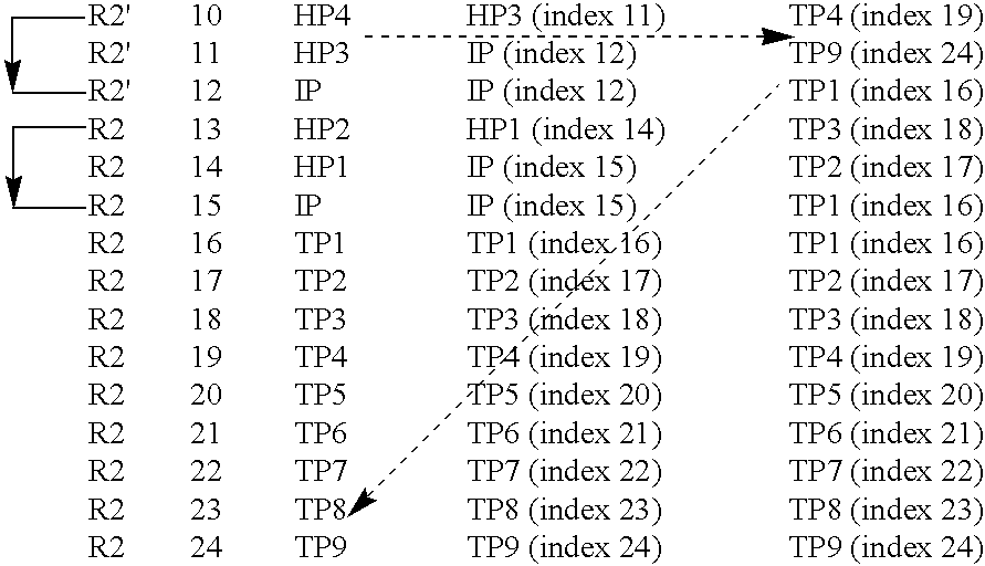
If the vehicle 100 is controlled to a termination waypoint TP1–TP9 because the command link has been broken during an extended time, the vehicle 100 will first circle in the air above the termination waypoint TP1–TP9 until a particular timer has elapsed. Then, the vehicle 100 initiates an emergency landing at the termination waypoint TP1–TP9. This will be described in further detail below with reference to the FIGS. 2, 4 and 5. In addition to the return waypoints HP1–HP7 and the termination waypoints TP1–TP9, the emergency route includes the approach point IP, over which the vehicle will circle in the air while awaiting a landing order from the control station before initiating a landing at the base location 130. Preferably, the approach point IP is also included in the primary route R1 because also on this route, a user prompted landing is generally desirable. Table 1 below describes the primary route R1, alternative emergency routes R2, R2′ (indicated with bold arrows) and their respective waypoints, return waypoints and termination waypoints.
TABLE 1
Alarm Handling
Route Index Waypoint Return Waypoint Termination Waypoint
Figure US07158877-20070102-C00001
Figure US07158877-20070102-C00002
The table 1 represents a high-level program sequence, which for each waypoint towards which the vehicle 100 is directed to fly specifies a return waypoint and a termination waypoint being applicable in case a major alarm condition occurs. For example, the first line, wherein in the second column has index=1, indicates conditions being applicable when the vehicle 100 flies towards a first waypoint WP1. Correspondingly, the second line, wherein in the second column has index=2, indicates conditions being applicable when the vehicle 100 flies towards a second waypoint WP2, and so on.
The program is then executed stepwise—one index after the other—such that after having passed a particular waypoint (say WP1) as specified in the third column, the procedure steps down one line (i.e. increments the index by one) and starts flying towards the subsequent waypoint (WP2). In this context, a waypoint is considered as having been passed if the vehicle 100 first approaches the waypoint, such that it becomes located within a particular distance from the waypoint, and then starts to move away from the waypoint. Naturally, in practice, each of the waypoints in the table 1 above is also associated with a set of geographical and physical data, for example indicating a latitude, a longitude, an altitude, a velocity and a maximal roll angle for the vehicle 100.
If a major alarm condition arises before the vehicle 100 has reached the waypoint towards which it is currently flying, the procedure checks the relevant column (4 or 5 in the table 1) of the active waypoint index for an applicable subsequent index, and jumps to this index. Then, the procedure continues from this waypoint index, and so on. The procedure stops whenever an approach point IP or a termination waypoint TP has been reached.
Hence, the table 1 specifies the primary route R1/R1′ when the vehicle 100 flies in the autonomous mode. The table 1 also specifies different emergency routes R2 to be applied in case of an alarm condition. However, the table 1 is applicable in the manual mode too. Namely in this case, the vehicle 100 repeatedly searches for a closest waypoint WP1–WP8 or IP, such that in case of an alarm condition, it may select an appropriate return waypoint HP1–HP7 or a termination waypoint TP1–TP9. Moreover, a mode switch from the manual mode to the autonomous mode may be performed at any time. When entering the autonomous mode this way, the vehicle 100 simply starts to fly towards the closest waypoint as indicated by the currently active waypoint index.
Below follows an example which further will elucidate the proposed method. If the command link 115 is interrupted during a sufficiently long interval after that the vehicle 100 has passed the waypoint WP3, however not yet has reached the waypoint WP4, the vehicle 100 diverts from the primary route R1. Instead, the vehicle 100 follows an emergency route R2′ towards the return waypoint HP4. Provided that the command link failure remains also after having passed the return waypoint HP4, the vehicle 100 continues towards the waypoint HP3 with a final destination at the approach point IP (see the indices 10, 11 and 12 in the table 1). Here, however, an engine failure occurs before the vehicle 100 has reached the return waypoint HP3. Therefore, the vehicle's 100 route is again altered. This time, the termination waypoint TP9 is its next destination, as opposed to the previously intended return waypoint HP3 (see index 11 in table 1). In this example, we assume that the engine failure cannot be resolved in due time. Hence, the vehicle 100 emergency lands (as safely as possible) at the termination waypoint TP9. Further details pertaining to the conditions for making the decisions to alter the vehicle's 100 path from the primary route R1/R1′ to the emergency route R2′, and while on the emergency route R2′, changing the return waypoint HP3 to the alternative destination TP9 will be described below with reference to the FIGS. 2, 4 and 5.
FIG. 2 shows a time line illustrating the time periods which determine the decisions made when altering the vehicle's 100 routes and destinations according to embodiments of the invention.
As already mentioned, the vehicle monitors a number of flight control parameters, among them a command link parameter which reflects a quality of the command link between the control station and the vehicle. A very simple measure in this regard is to define the quality in two discrete levels representing a connection state and an interruption state respectively. Of course, more precise quality levels may also be defined. Here, however, it is assumed that the command link is interrupted at a point in time t=0. If the command link is interrupted during a first time interval T1 (say 1 second) from this point in time t=0 (i.e. until t=t1), an alarm condition with respect to a minor command link failure is activated. A horizontal flight of the vehicle is initiated in connection with activating this alarm condition.
Normally, a short command link interruption (in the order of 1 second) can be tolerated without any particular precautionary actions being necessary. Should, however, the command link remain interrupted during a second time interval T2 (say 5 seconds), which significantly exceeds the first time interval T1 (i.e. from t=0 to t=t2; where t2>>t1), a major alarm condition with respect to a command link failure is activated. In this case, there is namely a substantial risk that the vehicle becomes uncontrollable. Therefore, the vehicle diverts from the primary route and starts following an emergency route, which involves flying the vehicle towards a base location on the ground (such as the runway 130 in FIG. 1). According to a preferred embodiment of the invention, at this point in time, the vehicle also elevates to a predetermined altitude. Both these measures, i.e. turning back and elevating, generally improve the radio conditions and thus increase the chances of reestablishing the command link. Moreover, elevating the vehicle generally reduces the risk of a crash landing.
If the command link returns (i.e. reconnects) before expiry of the second time interval, the minor alarm condition with respect to a command link failure is preferably cleared, and the flight control of the vehicle is returned to the mode in which the vehicle was controlled before the interruption in the command link.
Nevertheless, if not only the second time interval T2, but also a third and much longer time interval T3 (say 5 minutes from t=0) expires without the command link returning, the major alarm condition remains active and the emergency route is altered, such that it involves flying the vehicle to an air space above a termination waypoint. The length of the time interval T3 is generally selected with respect to the accuracy in the navigation of the vehicle, such that during the time interval T3 the vehicle may not divert unacceptably far from the intended route. In this example, it is presumed that the vehicle reaches the air space above the relevant termination waypoint (as determined by preprogrammed information in the vehicle) at a point in time t=t4. The vehicle then starts to circle over this termination waypoint. At expiry of a fourth time interval T4 (say in total 10 minutes after t=0) when t=t5, the vehicle initiates an emergency landing at the termination waypoint.
According to a preferred embodiment of the invention, the vehicle transmits a status message to the control station if the command link should return at any instance in time. The vehicle is then also enabled to receive overriding commands from the control station via the command link. Thereby, the control station is informed of the fact that there is a connection to the vehicle, and it may be decided that the flight according to the emergency route should be discontinued. Instead, the primary route may be resumed, for example in the autonomous preprogrammed flight control mode. Of course, any overriding commands from the control station may equally well involve transmission of the control commands to the vehicle in the form of a number of commands constituting an alternative set of predefined waypoints, i.e. in-flight programmed flight control. Alternatively, a manual flight control may be activated at this point.
FIG. 3 shows a block diagram over a signal processing system 300 according to an embodiment of the invention which includes a central processing unit 330 and a wireless interface unit 340. An on-board flight control system 310, a functional monitoring system 320 and an interfacing unit 350 are included in the central processing unit 330.
The on-board flight control system 310, in turn, contains an autonomous control sub-system 311 and a manual control sub-system 312. The autonomous control sub-system 311 is adapted to control the vehicle to fly according to a primary route defined by a first set of predefined waypoints, preferably stored in the sub-system 311. Correspondingly, the manual control sub-system 312 is adapted to control the vehicle to fly according to a primary route, however in accordance with real-time commands received from the control station 110. These commands arrive via the wireless command link 115, the wireless interface unit 340 and the interfacing unit 350 in the central processing unit 330. The wireless interface unit 340 is also adapted to send any status messages generated by the functional monitoring system 320 to the control station.
The functional monitoring system 320 is adapted to monitor a set of flight control parameters P1–Pn. In case any of these parameters P1–Pn falls outside an acceptable range, the functional monitoring system 320 sets a relevant major alarm condition. This, in turn, will result in that the vehicle initiates a flight according to an emergency route defined by a second set of stored waypoints. Additionally, if a less critical fault is encountered, the functional monitoring system 320 may set a minor alarm condition, which will not cause the vehicle to select the emergency route. A short interruption of the wireless command link constitutes one example of such a fault.
According to the invention, one of the flight control parameters, say P1, represents a vital engine parameter. In case this parameter decreases below a threshold value (e.g. implying that the rpm is insufficient), the functional monitoring system 320 sets a major alarm condition with respect to an engine failure. As a consequence thereof, the vehicle will take the emergency route to an air space above a termination waypoint on the ground at which it is estimated that the vehicle's flight may be ended without injuring any personnel or causing uncontrolled material damages.
Additionally, the wireless interface 340 may generate a signal F, which is sent to the functional monitoring system 320. This signal F is produced in order to indicate that the command link has been reestablished.
A more detailed description of the operation of the functional monitoring system 320 and its interaction with the other units in the central processing unit 330 will be described below with reference to FIG. 5. First however, the general method of controlling a UAV according to the invention will be described with reference to FIG. 4.
It is presumed that the UAV is controllable from a control station by means of a wireless command link. Moreover, the UAV may be controlled both in an autonomous mode wherein the vehicle flies according to a primary route defined by a first set of stored waypoints, and in a manual mode wherein the vehicle flies according to a primary route defined by flight control commands received via the wireless command link. A set of flight control parameters is monitored in both the autonomous and the manual mode. In case a major alarm condition occurs in any of the modes, the method involves flying the UAV according to an emergency route defined by a second set of predefined waypoints.
A particular procedure is devised to prevent the UAV from crash landing at an undesired location. Here, a first step 401 checks whether the vehicle's engine is in order. This may involve testing if one or more engine parameters, such as thrust force, temperature level, pressure level and rpm, lie within an acceptable range. If this is the case, the procedure loops back and stays in the step 401. However otherwise, a step 449 activates a major alarm condition with respect to an engine failure. Subsequently, a step 451 controls the UAV to fly (or glide fly) to an air space above a termination waypoint, where it is estimated that the UAV's flight may be ended without injuring personnel or causing any intolerable material damages.
Now, a more detailed procedure according to the preferred embodiments of the invention will be described with reference to FIG. 5. Steps 501, 549 and 551 are equivalent to the steps 401, 449 and 451 respectively in FIG. 4. However, according to this embodiment of the invention, if the check in the step 501 finds that the engine is in order, a following step 503 checks whether the command link also has an acceptable quality, and if so, the procedure loops back to the step 501. Otherwise, a step 505 follows.
The step 505 activates a link alarm, which at this stage is regarded as a minor alarm condition. Subsequently, a step 507 checks whether the first time interval has expired (see FIG. 2), and if not, the procedure loops back to the step 501. If, however, the first interval has expired, a step 509 follows. This step again checks whether the engine is in order, and if so, a step 511 follows. Otherwise, the procedure jumps to a step 549 in which an engine alarm is activated to represent a major alarm condition.
The step 511 checks whether the command link still has an acceptable quality, and if so, a step 513 follows in which the minor link alarm activated in the step 505 is cleared. After that, a step 515 transmits a status message to the control station (see 110 in FIG. 1). According to a preferred embodiment of the invention, an acknowledgement message from the control station in response to the status message is required before the flight control of the UAV may be returned to the control mode in which it was operated before the link alarm was activated. If the test in the step 511 is answered in the negative, the procedure continues to a step 516 which checks whether the second interval (see FIG. 2) has expired. If it is found that this interval is still running, the procedure loops back to the step 509. Otherwise, the link alarm is now regarded as a major alarm condition, and a step 517 follows, which orders the UAV to fly towards the base location (see e.g. 130 in FIG. 1). Then, a step 519 checks whether the engine operates as desired, and if so, a step 521 follows. Otherwise, the procedure jumps to the step 549.
The step 521 checks whether the command link has regained an acceptable quality, and if so, a step 523 follows in which the major link alarm is cleared. Additionally, the step 523 involves transmission of a status message to the control station. The control of the UAV may there after be resumed in the mode in which it was controlled before the link alarm was activated. However, also in this case, it is preferable that an acknowledgement message is received from the control station first.
Nevertheless, if the test in the step 521 produces a negative result, a step 525 follows, which checks whether the third interval (see FIG. 2) has expired. If this is the case, a step 531 follows. Otherwise, the procedure continues to a step 527, which checks whether the UAV has reached the base station, and if so the step 515 follows. If, however, the UAV has not yet reached the base station, the procedure loops back to the step 517 wherein it continues to fly towards the base station. The step 515 here transmits a status message indicating that the UAV has returned to the base station and may be landed. Either a landing maneuver is then automatically initiated (e.g. after reception of an acknowledgement message from the control station), or the UAV is landed manually by means of real-time flight control commands from the control station.
If the test in the step 525 finds that also the third interval has expired, a step 531 follows wherein the command link is checked once more. If the command link here is found to have an acceptable quality, a step 533 follows in which the major link alarm is cleared. The step 533 also involves transmission of a status message to the control station, where after the control of the UAV may be resumed in the mode in which the UAV was controlled before the link alarm was activated. Again, it is preferable that an acknowledgement message is received from the control station first.
If, it in the step 531 is found that the command link still has an unacceptably low quality, a step 535 follows which orders the UAV to fly towards a specified termination waypoint (see e.g. the table 1). Then, a step 537 checks whether the engine is in order, and if so, a step 539 follows. Otherwise, the procedure jumps to the step 549 in which an engine alarm is activated. The step 539 checks whether the fourth interval has expired (see FIG. 2), and if so, a step 541 follows. Otherwise, the procedure loops back to the step 535, such that the UAV continues to fly towards the termination waypoint. If, the UAV has already reached this point (i.e. before the fourth interval expires) the loop described by the steps 535, 537 and 539 implies that the UAV circles over the termination waypoint until the fourth interval expires.
The step 541 checks whether the command link has an acceptable quality, and if so, the step 533 follows wherein the major link alarm is cleared and a status message is transmitted to the control station, where after the control of the UAV may be resumed in the mode in which the UAV was controlled before the link alarm was activated. Again, it is preferable that an acknowledgement message is received from the control station first. If the step 541 finds that the command link still has an unacceptably low quality, the procedure continues to a step 543 in which a termination of the flight is initiated at the termination waypoint (which the UAV now shall have reached). Subsequently, a step 545 checks whether the termination has been completed, i.e. if the UAV's flight is stopped permanently. If so, the procedure ends in a step 547 which indicates that a successful termination has been accomplished. Otherwise, the procedure loops back to the step 541, and whatever measures which remain to complete the termination are performed. For example, this may mean that the circulation maneuvers over the termination point are continued with a gradually lowered altitude.
The step 549, which indicates an engine alarm, may be entered from any of the steps 501, 509, 519 or 537 if it is found that the engine is malfunctioning. In any case, after the step 549 follows a step 551 in which the UAV is ordered to fly, or if the engine has stalled, glide fly towards a specified termination waypoint (see e.g. the table 1). Subsequently, a step 553 checks whether the engine is operating satisfactory. The engine problem may namely have been resolved since the engine alarm was activated, and if so, the engine alarm is cleared in a step 555 and a corresponding status message is transmitted to the control station, such that the termination procedure may be interrupted by means of a manual intervention. If, however, the step 553 finds that the engine is still out of order, the procedure continues to a step 557, which checks whether the UAV has reached the specified termination waypoint. If this is not the case, the procedure loops back to the step 551. Otherwise, however, a step 559 following the step 557 initiates a termination process at the termination waypoint. After that, the procedure ends in the step 547, which indicates that a successful termination has been accomplished.
Thus, the step 547 represents a definitive end of the procedure. Although the procedure according to the flow chart also ends in each of the steps 515, 523, 533 and 555, these steps instead imply returning the procedure to the start step, preferably after reception of an acknowledgement message from the control station.
All of the process steps, as well as any sub-sequence of steps, described with reference to the FIGS. 4 and 5 above may be controlled by means of a programmed computer apparatus, preferably located in an on-board central processor of an unmanned aerial vehicle's signal processing system. Moreover, although the embodiments of the invention described above with reference to the drawings comprise computer apparatus and processes performed in computer apparatus, the invention thus also extends to computer programs, particularly computer programs on or in a carrier, adapted for putting the invention into practice. The program may be in the form of source code, object code, a code intermediate source and object code such as in partially compiled form, or in any other form suitable for use in the implementation of the process according to the invention. The carrier may be any entity or device capable of carrying the program. For example, the carrier may comprise a storage medium, such as a ROM (Read Only Memory), for example a CD (Compact Disc) or a semiconductor ROM, or a magnetic recording medium, for example a floppy disc or hard disc. Further, the carrier may be a transmissible carrier such as an electrical or optical signal which may be conveyed via electrical or optical cable or by radio or by other means. When the program is embodied in a signal which may be conveyed directly by a cable or other device or means, the carrier may be constituted by such cable or device or means. Alternatively, the carrier may be an integrated circuit in which the program is embedded, the integrated circuit being adapted for performing, or for use in the performance of, the relevant processes.
The term “comprises/comprising” when used in this specification is taken to specify the presence of stated features, integers, steps or components. However, the term does not preclude the presence or addition of one or more additional features, integers, steps or components or groups thereof.
The invention is not restricted to the described embodiments in the figures, but may be varied freely within the scope of the claims.

Claims (22)

1. A method of controlling an unmanned aerial vehicle from a control station by means of a wireless command link, involving:
flight control in an autonomous mode wherein the vehicle flies according to a primary route defined by a first set of predefined waypoints,
flight control in a manual mode wherein the vehicle flies according to a primary route defined by control commands received via the wireless command link, and
functional monitoring of a set of flight control parameters in both the autonomous mode and the manual mode, wherein if, in any of the modes, at least one of the flight control parameters falls outside an acceptable range a major alarm condition is activated, the method involves flying the vehicle according to an emergency route defined by a second set of predefined waypoints, wherein the set of flight control parameters including at least one engine parameter, the method comprising:
activating a major alarm condition with respect to an engine failure in case at least one of the at least one engine parameter decreases below a threshold value, and in such case,
the emergency route involves flying the vehicle to an air space above a termination waypoint on the ground at which it is estimated that the vehicle's flight may be ended without injuring any personnel or causing uncontrolled material damages.
2. The method according to claim 1, wherein the set of flight control parameters includes a command link parameter, the method comprising:
activating a minor alarm condition with respect to a command link failure in case the command link is interrupted during a first time interval, and in such case,
initiating a horizontal flight of the vehicle.
3. The method according to claim 2, wherein the method comprises:
activating a major alarm condition with respect to a command link failure in case the command link is interrupted during a second time interval exceeding said first time interval, and in such case,
the emergency route involves flying the vehicle towards a base location on the ground.
4. The method according to claim 3, wherein the vehicle is flown towards the base location involving elevating the vehicle to a predetermined altitude.
5. The method according to claim 3, further comprising:
clearing the minor alarm condition with respect to a command link failure in case the command link returns before expiry of the second time interval, and
returning the flight control of the vehicle to the mode in which the vehicle was controlled before the interruption in the command link.
6. A method according to claim 3, wherein in case of a major alarm condition with respect to a command link failure, the command link remains interrupted during a third time interval exceeding said second time interval, the emergency route involves flying the vehicle to an air space above a termination waypoint on the ground at which it is estimated that the vehicle's flight may be ended without injuring any personnel or causing uncontrolled material damages.
7. The method according to claim 6, wherein in case of a major alarm condition with respect to a command link failure, the command link remains interrupted during a fourth time interval exceeding said third time interval, initiating an emergency landing of the vehicle at the termination waypoint.
8. The method according to claim 2, wherein in case the command link returns at any instance in time, a link status message is transmitted from the vehicle to the control station, the link status message indicating a functioning condition for the command link.
9. The method according to claim 8, wherein after transmission of the link status message, the method further comprises:
enabling the vehicle to receive overriding commands from the control station via the command link,
discontinuing a flight according to the emergency route in case overriding commands are received, and in such case
enabling a flight control according to the manual mode.
10. The method according to claim 1, wherein the autonomous flight control mode includes transmission of the control commands to the vehicle in the form of a number of commands constituting an alternative set of waypoints.
11. The method according to claim 1, wherein the manual flight control mode includes transmission of the control commands to the vehicle in the form of real-time commands.
12. The method according to claim 1, further comprising:
selecting points from the first set of predefined waypoints from an indexed table by means of a stepwise procedure, and
selecting points from the second set of predefined waypoints by means of jumping from a first line in the indexed table to a second line in the indexed table, the second line being specified on said first line.
13. A computer program directly loadable into the internal memory of a digital computer, comprising software for accomplishing the steps of claim 1 when said program is run on a computer.
14. A computer readable medium, having a program recorded thereon, where the program is to make a computer accomplish the steps of claim 1.
15. An unmanned aerial vehicle controllable from a control station by means of a wireless command link comprising
an on-board flight control system including:
an autonomous control sub-system adapted to control the vehicle to fly according to a primary route defined by a first set of predefined waypoints, and
a manual control sub-system adapted to receive commands from the control station via the wireless command link, and control the vehicle to fly according to a primary route defined by the commands from the control station, and
a functional monitoring system adapted to monitor a set of flight control parameters, and in case at least one of the flight control parameters falls outside an acceptable range, set a major alarm condition and initiate a flight of the vehicle according to an emergency route defined by a second set of predefined waypoints, wherein the set of flight control parameters includes at least one engine parameter, and the functional monitoring system is adapted to, in case at least one of the at least one engine parameter decreases below a threshold value, set an alarm condition with respect to an engine failure, and fly the vehicle according to the emergency route to an air space above a termination waypoint on the ground at which it is estimated that the vehicle's flight may be ended without injuring any personnel or causing uncontrolled material damages.
16. The unmanned aerial vehicle according to claim 15, wherein the functional monitoring system is adapted to monitor the wireless command link, and in case the command link is interrupted during a first time interval: activate an alarm condition with respect to a minor command link failure, and
initiate a horizontal flight of the vehicle.
17. The unmanned aerial vehicle according to claim 16, wherein the functional monitoring system is adapted to, in case the command link is interrupted during a second time interval exceeding said first time interval: activate a major alarm condition with respect to a command link failure, and
fly the vehicle towards a base location on the ground.
18. The unmanned aerial vehicle according to claim 17, wherein the functional monitoring system is adapted to, in case the command link returns before expiry of the second time interval:
clear the alarm condition with respect to the minor command link failure, and
return the flight control of the vehicle to the control sub-system which controlled the vehicle before the interruption in the command link.
19. The unmanned aerial vehicle according to claim 17, wherein the functional monitoring system is adapted to, in case of a major alarm condition with respect to a command link failure, the command link remains interrupted during a third time interval exceeding said second time interval, fly the vehicle to an air space above a termination waypoint on the ground at which it is estimated that the vehicle's flight may be ended without injuring any personnel or causing uncontrolled material damages.
20. The unmanned aerial vehicle according to claim 17, wherein the functional monitoring system is adapted to initiate a landing of the vehicle at the termination waypoint, if at the expiry of a fourth time interval after that the command link failure occurred, the command link failure remains; the fourth time interval exceeding said third time interval.
21. The unmanned aerial vehicle according to claim 16, wherein the functional monitoring system is adapted to, in case the command link returns at any instance in time, generate a link status message indicating a functioning condition for the command link.
22. The unmanned aerial vehicle according to claim 21, wherein the functional monitoring system is adapted to, after that the link status message has been transmitted to the control station:
enable the vehicle to receive overriding commands from the control station via the command link,
discontinue a flight according to the emergency route in case overriding commands are received, and in such case
enable activation of the manual control sub-system.
US10/720,756 2003-03-27 2003-11-25 Waypoint navigation Active 2025-06-21 US7158877B2 (en)

Applications Claiming Priority (2)

Application Number Priority Date Filing Date Title
SE0300871-1 2003-03-27
SE0300871A SE0300871D0 (en) 2003-03-27 2003-03-27 Waypoint navigation

Publications (2)

Publication Number Publication Date
US20040193334A1 US20040193334A1 (en) 2004-09-30
US7158877B2 true US7158877B2 (en) 2007-01-02

Family

ID=20290822

Family Applications (1)

Application Number Title Priority Date Filing Date
US10/720,756 Active 2025-06-21 US7158877B2 (en) 2003-03-27 2003-11-25 Waypoint navigation

Country Status (4)

Country Link
US (1) US7158877B2 (en)
EP (1) EP1462898B1 (en)
ES (1) ES2660874T3 (en)
SE (1) SE0300871D0 (en)

Cited By (36)

* Cited by examiner, † Cited by third party
Publication number Priority date Publication date Assignee Title
US20060106506A1 (en) * 2004-11-16 2006-05-18 Nichols William M Automatic contingency generator
US20060167599A1 (en) * 2005-01-24 2006-07-27 Bodin William K Identifying a UAV landing location
US20070018052A1 (en) * 2004-07-03 2007-01-25 Saab Ab A system and method for in-flight control of an aerial vehicle
US20070120708A1 (en) * 2005-09-09 2007-05-31 Honeywell International Inc. Methods and systems for monitoring aircraft approach between approach gates
US20080147309A1 (en) * 2006-06-30 2008-06-19 Saab Ab Termination secured route planning
US20090063032A1 (en) * 2007-08-30 2009-03-05 Honeywell International, Inc. Methods, systems, and apparatus for routing a vehicle to avoid an adverse condition
US20090245116A1 (en) * 2008-03-26 2009-10-01 Honeywell International Inc. Method for mobile network operational state indication
US20100017114A1 (en) * 2007-05-24 2010-01-21 Honeywell International Inc. Flight Path Planning to Reduce Detection of an Unmanned Aerial Vehicle
US7681832B2 (en) 2007-05-02 2010-03-23 Honeywell International Inc. Ducted fan air vehicle with deployable wings
US20100084513A1 (en) * 2008-09-09 2010-04-08 Aeryon Labs Inc. Method and system for directing unmanned vehicles
US20100108809A1 (en) * 2008-10-31 2010-05-06 Honeywell International Inc. Noise-suppressing strut support system for an unmanned aerial vehicle
US20100187369A1 (en) * 2009-01-26 2010-07-29 Honeywell International Inc. Ducted fan uav control alternatives
US20100215212A1 (en) * 2009-02-26 2010-08-26 Honeywell International Inc. System and Method for the Inspection of Structures
US20100228406A1 (en) * 2009-03-03 2010-09-09 Honeywell International Inc. UAV Flight Control Method And System
US20100256839A1 (en) * 2009-04-02 2010-10-07 Honeywell International Inc. Performing Corrective Action on Unmanned Aerial Vehicle Using One Axis of Three-Axis Magnetometer
US20110001017A1 (en) * 2008-12-08 2011-01-06 Honeywell International Inc. Uav ducted fan swept and lean stator design
US20110095530A1 (en) * 2009-10-26 2011-04-28 Honeywell International Inc. Tethered aquatic device with water power turbine
US20110320068A1 (en) * 2010-06-24 2011-12-29 Hon Hai Precision Industry Co., Ltd. Electronic device and method for controlling unmanned aerial vehicle using the same
US8109711B2 (en) 2008-07-18 2012-02-07 Honeywell International Inc. Tethered autonomous air vehicle with wind turbines
US8150621B1 (en) 2009-04-07 2012-04-03 The United States of America as represeneted by the Secretary of the Navy Command and control of autonomous surface vehicle
US20130060405A1 (en) * 2010-06-07 2013-03-07 Toyota Jidosha Kabushiki Kaisha Flight control support device
US8798922B2 (en) * 2012-11-16 2014-08-05 The Boeing Company Determination of flight path for unmanned aircraft in event of in-flight contingency
US20140236387A1 (en) * 2012-08-02 2014-08-21 Sikorksy Aircraft Corporation Clickable camera window
US8897931B2 (en) * 2011-08-02 2014-11-25 The Boeing Company Flight interpreter for captive carry unmanned aircraft systems demonstration
US9004393B2 (en) 2010-10-24 2015-04-14 University Of Kansas Supersonic hovering air vehicle
WO2015114572A1 (en) * 2014-01-31 2015-08-06 Tata Consultancy Services Limited A computer implemented system and method for providing robust communication links to unmanned aerial vehicles
US20160070265A1 (en) * 2014-09-05 2016-03-10 SZ DJI Technology Co., Ltd Multi-sensor environmental mapping
CN105841702A (en) * 2016-03-10 2016-08-10 赛度科技(北京)有限责任公司 Method for planning routes of multi-unmanned aerial vehicles based on particle swarm optimization algorithm
US9592911B2 (en) 2014-09-05 2017-03-14 SZ DJI Technology Co., Ltd Context-based flight mode selection
US9625907B2 (en) 2014-09-05 2017-04-18 SZ DJ Technology Co., Ltd Velocity control for an unmanned aerial vehicle
RU2634470C2 (en) * 2013-03-19 2017-10-30 Зе Боинг Компани Method of piloting unmanned flying apparatus
US20180091217A1 (en) * 2015-03-02 2018-03-29 Uavia System for transmitting commands and a video stream between a remote controlled machine such as a drone and a ground station
US10073454B2 (en) 2016-03-17 2018-09-11 Northrop Grumman Systems Corporation Machine vision enabled swarm guidance technology
US10240930B2 (en) 2013-12-10 2019-03-26 SZ DJI Technology Co., Ltd. Sensor fusion
US10319245B2 (en) * 2015-12-28 2019-06-11 Kddi Corporation Flight vehicle control device, flight permitted airspace setting system, flight vehicle control method and program
US10423831B2 (en) 2017-09-15 2019-09-24 Honeywell International Inc. Unmanned aerial vehicle based expansion joint failure detection system

Families Citing this family (85)

* Cited by examiner, † Cited by third party
Publication number Priority date Publication date Assignee Title
US10331121B2 (en) * 2006-04-17 2019-06-25 Ge Global Sourcing Llc Vehicle communication system
US10457281B2 (en) * 2017-01-23 2019-10-29 Ge Global Sourcing Llc Vehicle communication system
US7343232B2 (en) * 2003-06-20 2008-03-11 Geneva Aerospace Vehicle control system including related methods and components
US8086351B2 (en) * 2004-02-06 2011-12-27 Icosystem Corporation Methods and systems for area search using a plurality of unmanned vehicles
US20080243321A1 (en) 2005-02-11 2008-10-02 Econtrols, Inc. Event sensor
US7756614B2 (en) * 2004-02-27 2010-07-13 Hewlett-Packard Development Company, L.P. Mobile device control system
ES2245245B1 (en) 2004-06-08 2007-02-16 INSTITUTO NACIONAL DE TECNICA AEROESPACIAL "ESTEBAN TERRADAS" SYSTEM AND METHOD OF CONTROL OF AN UNTRIPULATED AIR VEHICLE.
US7818127B1 (en) * 2004-06-18 2010-10-19 Geneva Aerospace, Inc. Collision avoidance for vehicle control systems
US7228232B2 (en) * 2005-01-24 2007-06-05 International Business Machines Corporation Navigating a UAV with obstacle avoidance algorithms
US9207675B1 (en) 2005-02-11 2015-12-08 Enovation Controls, Llc Event sensor
US20070131822A1 (en) * 2005-06-20 2007-06-14 Kevin Leigh Taylor Stallard Aerial and ground robotic system
EP1923762A4 (en) * 2005-09-05 2009-11-18 Otkrytoe Aktsionernoe Obschest Method and a set of means for piloting an aircraft
US7874521B2 (en) * 2005-10-17 2011-01-25 Hoshiko Llc Method and system for aviation navigation
US7970506B2 (en) * 2006-01-19 2011-06-28 Lockheed Martin Corporation System for maintaining communication between teams of vehicles
EP1847896B1 (en) * 2006-04-20 2018-03-21 Saab Ab Termination map for an aircraft
ES2616545T3 (en) * 2006-04-20 2017-06-13 Saab Ab Emergency flight plan
US8139109B2 (en) 2006-06-19 2012-03-20 Oshkosh Corporation Vision system for an autonomous vehicle
US8947531B2 (en) * 2006-06-19 2015-02-03 Oshkosh Corporation Vehicle diagnostics based on information communicated between vehicles
US20100250022A1 (en) * 2006-12-29 2010-09-30 Air Recon, Inc. Useful unmanned aerial vehicle
FR2916841B1 (en) * 2007-05-29 2009-09-11 Thales Sa METHOD FOR PRODUCING AN AIRCRAFT FLIGHT PLAN
JP5047709B2 (en) * 2007-07-04 2012-10-10 株式会社日立製作所 Moving device, system, moving method, and moving program
ES2416707T3 (en) * 2008-08-08 2013-08-02 Saab Ab System of safely lowering a UAV
US8543265B2 (en) * 2008-10-20 2013-09-24 Honeywell International Inc. Systems and methods for unmanned aerial vehicle navigation
US8515596B2 (en) * 2009-08-18 2013-08-20 Honeywell International Inc. Incremental position-based guidance for a UAV
US8594932B2 (en) 2010-09-14 2013-11-26 The Boeing Company Management system for unmanned aerial vehicles
CN102464108A (en) * 2010-11-01 2012-05-23 成都飞机工业(集团)有限责任公司 Engine failure treating method for unmanned aerial vehicle
CN102331783B (en) * 2011-06-17 2013-03-13 沈阳航空航天大学 Autopilot for indoor airship
CN102955478B (en) * 2012-10-24 2016-01-20 深圳一电科技有限公司 UAV flight control method and system
CN102980581A (en) * 2012-12-07 2013-03-20 北京中海新图科技有限公司 Irregular-island-based method for planning covered flight route of unmanned aerial vehicle
US9567074B2 (en) 2012-12-19 2017-02-14 Elwha Llc Base station control for an unoccupied flying vehicle (UFV)
US9540102B2 (en) 2012-12-19 2017-01-10 Elwha Llc Base station multi-vehicle coordination
US10279906B2 (en) 2012-12-19 2019-05-07 Elwha Llc Automated hazard handling routine engagement
US10518877B2 (en) 2012-12-19 2019-12-31 Elwha Llc Inter-vehicle communication for hazard handling for an unoccupied flying vehicle (UFV)
US9527587B2 (en) 2012-12-19 2016-12-27 Elwha Llc Unoccupied flying vehicle (UFV) coordination
US9776716B2 (en) 2012-12-19 2017-10-03 Elwah LLC Unoccupied flying vehicle (UFV) inter-vehicle communication for hazard handling
US9405296B2 (en) 2012-12-19 2016-08-02 Elwah LLC Collision targeting for hazard handling
US9747809B2 (en) 2012-12-19 2017-08-29 Elwha Llc Automated hazard handling routine activation
US9235218B2 (en) 2012-12-19 2016-01-12 Elwha Llc Collision targeting for an unoccupied flying vehicle (UFV)
US9669926B2 (en) 2012-12-19 2017-06-06 Elwha Llc Unoccupied flying vehicle (UFV) location confirmance
US9527586B2 (en) 2012-12-19 2016-12-27 Elwha Llc Inter-vehicle flight attribute communication for an unoccupied flying vehicle (UFV)
US9810789B2 (en) 2012-12-19 2017-11-07 Elwha Llc Unoccupied flying vehicle (UFV) location assurance
FR3001288B1 (en) * 2013-01-18 2015-03-20 Dassault Aviat METHOD FOR DEFINING A REPLY ROAD FOR A MOBILE MACHINE, METHOD OF FALLING, BY A MOBILE VEHICLE, OF SUCH A ROAD, COMPUTER MODULES AND COMPUTER PROGRAMS
US9676472B2 (en) * 2013-08-30 2017-06-13 Insitu, Inc. Systems and methods for configurable user interfaces
ES2908842T3 (en) 2013-09-26 2022-05-04 Airbus Defence & Space Gmbh Method for the autonomous control of an aerial vehicle and corresponding system
EP2853974A1 (en) * 2013-09-26 2015-04-01 Airbus Defence and Space GmbH Method for autonomous controlling of a remote controlled aerial vehicle and corresponding system
EP2871495B1 (en) * 2013-11-11 2020-06-03 Airbus Defence and Space GmbH Aircraft navigation system and method of navigating an aircraft
US9557742B2 (en) 2013-11-27 2017-01-31 Aurora Flight Sciences Corporation Autonomous cargo delivery system
CA2935457C (en) 2014-01-10 2022-08-09 Pictometry International Corp. Unmanned aircraft structure evaluation system and method
ES2549464B1 (en) * 2014-03-28 2016-05-27 Univ Huelva SALVAMENT SYSTEM
JP2015203938A (en) * 2014-04-14 2015-11-16 株式会社Ihi Abnormal-time return control method for autonomous vehicle and autonomous vehicle for use to implement abnormal-time return control method
JP6133506B2 (en) 2014-04-17 2017-05-24 エスゼット ディージェイアイ テクノロジー カンパニー リミテッドSz Dji Technology Co.,Ltd Flight control for flight restricted areas
EP2942688A1 (en) * 2014-05-05 2015-11-11 Puy du Fou International Flying drone and method for controlling a flying drone
US9335764B2 (en) * 2014-05-27 2016-05-10 Recreational Drone Event Systems, Llc Virtual and augmented reality cockpit and operational control systems
US20160042637A1 (en) * 2014-08-11 2016-02-11 Clandestine Development, Llc Drone Safety Alert Monitoring System and Method
US11157021B2 (en) * 2014-10-17 2021-10-26 Tyco Fire & Security Gmbh Drone tours in security systems
FR3030794B1 (en) * 2014-12-23 2016-12-23 Thales Sa METHOD AND SYSTEM FOR GUIDING AN AIRCRAFT
JP6671375B2 (en) * 2014-12-25 2020-03-25 エスゼット ディージェイアイ テクノロジー カンパニー リミテッドSz Dji Technology Co.,Ltd How to fly a drone
JP6423521B2 (en) 2015-03-31 2018-11-14 エスゼット ディージェイアイ テクノロジー カンパニー リミテッドSz Dji Technology Co.,Ltd System for controlling unmanned aerial vehicles
WO2016154945A1 (en) * 2015-03-31 2016-10-06 SZ DJI Technology Co., Ltd. Authentication systems and methods for detecting unauthorized uav activity
EP3152089A4 (en) 2015-03-31 2017-08-02 SZ DJI Technology Co., Ltd. Systems and methods for geo-fencing device communications
EP3164775B1 (en) 2015-03-31 2023-03-22 SZ DJI Technology Co., Ltd. Open platform for flight restricted region
IL238318B (en) * 2015-04-16 2020-09-30 Israel Aerospace Ind Ltd Control interface for uxv
CN104751682B (en) * 2015-04-21 2017-06-16 中国航空工业集团公司沈阳飞机设计研究所 A kind of method, apparatus and system for building UAS dynamic lane
DE102015008256B4 (en) 2015-06-26 2017-07-06 Diehl Defence Gmbh & Co. Kg Defense drone to ward off small drones
EP3139542A1 (en) * 2015-09-07 2017-03-08 BAE Systems PLC Management of wireless communication links from a moving platform
DE102015012477A1 (en) * 2015-09-29 2017-03-30 Airbus Defence and Space GmbH Unmanned aerial vehicle and method for the safe landing of an unmanned aerial vehicle
EP3408718A4 (en) 2016-01-29 2019-08-21 Rolls-Royce Oy Ab An arrangement for defining a state for a marine vessel
CN105652884A (en) * 2016-02-15 2016-06-08 英华达(上海)科技有限公司 Unmanned aerial vehicle flying method and unmanned aerial vehicle flying system
CN106054917A (en) * 2016-05-27 2016-10-26 广州极飞电子科技有限公司 Unmanned aerial vehicle flight control method and device, and remote controller
US10571908B2 (en) 2016-08-15 2020-02-25 Ford Global Technologies, Llc Autonomous vehicle failure mode management
DE102016013114A1 (en) 2016-11-03 2018-05-03 Diehl Defence Gmbh & Co. Kg Device and method for repelling a drone
WO2018110088A1 (en) * 2016-12-12 2018-06-21 株式会社自律制御システム研究所 Unmanned aircraft and method for controlling unmanned aircraft
WO2019000404A1 (en) * 2017-06-30 2019-01-03 深圳市大疆创新科技有限公司 Control terminal, unmanned aerial vehicle and control method therefor
US20200175882A1 (en) * 2017-08-04 2020-06-04 ideaForge Technology Pvt. Ltd Uav system emergency path planning on communication failure
WO2019041246A1 (en) * 2017-08-31 2019-03-07 深圳市大疆创新科技有限公司 Method and device for retrieving unmanned aerial vehicle upon interruption of communication link, and computation device
US10611381B2 (en) 2017-10-24 2020-04-07 Ford Global Technologies, Llc Decentralized minimum risk condition vehicle control
US10726645B2 (en) 2018-02-16 2020-07-28 Ford Global Technologies, Llc Vehicle diagnostic operation
US11142347B1 (en) * 2018-05-15 2021-10-12 AST&Defense, LLC System and method for the assembly of large distributed structures in space
TWI696907B (en) * 2018-11-26 2020-06-21 財團法人工業技術研究院 Method and device for communication failure detection
DE102019104866A1 (en) 2019-02-26 2020-08-27 Rheinmetall Waffe Munition Gmbh Drone and anti-targeting methods
KR102243823B1 (en) * 2019-03-14 2021-04-23 주식회사 엘지유플러스 Control server and method for setting flight path of unmanned aerial vehicle using this
CN110118557A (en) 2019-04-24 2019-08-13 深圳市道通智能航空技术有限公司 A kind of course line joining method, system and user terminal
CN110816864A (en) * 2019-12-17 2020-02-21 淮安航空产业研究院有限公司 Special reconnaissance unmanned aerial vehicle for emergency rescue, system and emergency rescue method thereof
CN111240354B (en) * 2020-01-09 2022-07-12 深圳市道通智能航空技术股份有限公司 Unmanned aerial vehicle severe low-power protection method and unmanned aerial vehicle
DE102021001294B3 (en) 2021-03-10 2022-08-18 Mbda Deutschland Gmbh Methods for the adaptive protection of airborne weapon systems

Citations (11)

* Cited by examiner, † Cited by third party
Publication number Priority date Publication date Assignee Title
US5526265A (en) 1991-12-17 1996-06-11 The Boeing Company Alternate destination predictor for aircraft
US5842142A (en) * 1995-05-15 1998-11-24 The Boeing Company Least time alternate destination planner
US5906336A (en) 1997-11-14 1999-05-25 Eckstein; Donald Method and apparatus for temporarily interconnecting an unmanned aerial vehicle
US6043757A (en) * 1998-06-12 2000-03-28 The Boeing Company Dynamic, multi-attribute hazard prioritization system for aircraft
US6377875B1 (en) * 1998-10-29 2002-04-23 Daimlerchrysler Ag Method for remote-controlling an unmanned aerial vehicle
US6519527B2 (en) * 2001-03-19 2003-02-11 Kabushiki Kaisha Toshiba Navigation assisting system, flight-route calculating method, and navigation assisting method
US20030144769A1 (en) * 2001-11-22 2003-07-31 Dieter Meier Security system for preventing aircraft hijacking
US20030206119A1 (en) * 2002-03-14 2003-11-06 Honeywell Inc. Flight safety system monitoring combinations of state values
US6739556B1 (en) * 2002-11-20 2004-05-25 Raytheon Company Method and apparatus for providing an aircraft emergency safety control system
US6922631B1 (en) * 2000-10-06 2005-07-26 Honeywell International Inc. System and method for textually displaying an original flight plan and a modified flight plan simultaneously
US7006904B2 (en) * 2001-09-28 2006-02-28 Pippenger Phillip Mckinney Anti-hijacking security system and apparatus for aircraft

Family Cites Families (9)

* Cited by examiner, † Cited by third party
Publication number Priority date Publication date Assignee Title
US4500966A (en) 1982-05-26 1985-02-19 Chandler Evans Inc. Super contingency aircraft engine control
US4818990A (en) 1987-09-11 1989-04-04 Fernandes Roosevelt A Monitoring system for power lines and right-of-way using remotely piloted drone
US4896154A (en) 1987-10-28 1990-01-23 Eventide Inc. Map display system for vehicle navigation
FR2721458B1 (en) 1994-06-15 1996-09-13 Aerospatiale Observation system by remote pilot aircraft.
US5785281A (en) * 1994-11-01 1998-07-28 Honeywell Inc. Learning autopilot
IL117792A (en) 1995-05-08 2003-10-31 Rafael Armament Dev Authority Autonomous command and control unit for mobile platform
US6460810B2 (en) 1996-09-06 2002-10-08 Terry Jack James Semiautonomous flight director
DE10023016B4 (en) 2000-05-05 2009-10-08 UMS Umwelt-Meßflug-Systeme GmbH Aircraft and propulsion system and control method
WO2003004352A1 (en) 2001-07-06 2003-01-16 Seiko Epson Corporation Airship system

Patent Citations (11)

* Cited by examiner, † Cited by third party
Publication number Priority date Publication date Assignee Title
US5526265A (en) 1991-12-17 1996-06-11 The Boeing Company Alternate destination predictor for aircraft
US5842142A (en) * 1995-05-15 1998-11-24 The Boeing Company Least time alternate destination planner
US5906336A (en) 1997-11-14 1999-05-25 Eckstein; Donald Method and apparatus for temporarily interconnecting an unmanned aerial vehicle
US6043757A (en) * 1998-06-12 2000-03-28 The Boeing Company Dynamic, multi-attribute hazard prioritization system for aircraft
US6377875B1 (en) * 1998-10-29 2002-04-23 Daimlerchrysler Ag Method for remote-controlling an unmanned aerial vehicle
US6922631B1 (en) * 2000-10-06 2005-07-26 Honeywell International Inc. System and method for textually displaying an original flight plan and a modified flight plan simultaneously
US6519527B2 (en) * 2001-03-19 2003-02-11 Kabushiki Kaisha Toshiba Navigation assisting system, flight-route calculating method, and navigation assisting method
US7006904B2 (en) * 2001-09-28 2006-02-28 Pippenger Phillip Mckinney Anti-hijacking security system and apparatus for aircraft
US20030144769A1 (en) * 2001-11-22 2003-07-31 Dieter Meier Security system for preventing aircraft hijacking
US20030206119A1 (en) * 2002-03-14 2003-11-06 Honeywell Inc. Flight safety system monitoring combinations of state values
US6739556B1 (en) * 2002-11-20 2004-05-25 Raytheon Company Method and apparatus for providing an aircraft emergency safety control system

Non-Patent Citations (1)

* Cited by examiner, † Cited by third party
Title
Schiller I et al., Mobile Robots VII USA Nov. 18-20, 1992, Abstract, Database Inspec/IEE.

Cited By (62)

* Cited by examiner, † Cited by third party
Publication number Priority date Publication date Assignee Title
US20070018052A1 (en) * 2004-07-03 2007-01-25 Saab Ab A system and method for in-flight control of an aerial vehicle
AU2005229702B2 (en) * 2004-11-16 2011-04-21 Northrop Grumman Systems Corporation Automatic contingency generator
US7512462B2 (en) * 2004-11-16 2009-03-31 Northrop Grumman Corporation Automatic contingency generator
US20060106506A1 (en) * 2004-11-16 2006-05-18 Nichols William M Automatic contingency generator
US20060167599A1 (en) * 2005-01-24 2006-07-27 Bodin William K Identifying a UAV landing location
US20070120708A1 (en) * 2005-09-09 2007-05-31 Honeywell International Inc. Methods and systems for monitoring aircraft approach between approach gates
US20080147309A1 (en) * 2006-06-30 2008-06-19 Saab Ab Termination secured route planning
US7937191B2 (en) * 2006-06-30 2011-05-03 Saab Ab Termination secured route planning
US7681832B2 (en) 2007-05-02 2010-03-23 Honeywell International Inc. Ducted fan air vehicle with deployable wings
US20100017114A1 (en) * 2007-05-24 2010-01-21 Honeywell International Inc. Flight Path Planning to Reduce Detection of an Unmanned Aerial Vehicle
US7970532B2 (en) 2007-05-24 2011-06-28 Honeywell International Inc. Flight path planning to reduce detection of an unmanned aerial vehicle
US20090063032A1 (en) * 2007-08-30 2009-03-05 Honeywell International, Inc. Methods, systems, and apparatus for routing a vehicle to avoid an adverse condition
US20090245116A1 (en) * 2008-03-26 2009-10-01 Honeywell International Inc. Method for mobile network operational state indication
US7835316B2 (en) 2008-03-26 2010-11-16 Honeywell International Inc. Method for mobile network operational state indication
US8109711B2 (en) 2008-07-18 2012-02-07 Honeywell International Inc. Tethered autonomous air vehicle with wind turbines
US8521339B2 (en) 2008-09-09 2013-08-27 Aeryon Labs Inc. Method and system for directing unmanned vehicles
US20100084513A1 (en) * 2008-09-09 2010-04-08 Aeryon Labs Inc. Method and system for directing unmanned vehicles
US20100108809A1 (en) * 2008-10-31 2010-05-06 Honeywell International Inc. Noise-suppressing strut support system for an unmanned aerial vehicle
US8070092B2 (en) 2008-10-31 2011-12-06 Honeywell International Inc. Noise-suppressing strut support system for an unmanned aerial vehicle
US20110001017A1 (en) * 2008-12-08 2011-01-06 Honeywell International Inc. Uav ducted fan swept and lean stator design
US20100187369A1 (en) * 2009-01-26 2010-07-29 Honeywell International Inc. Ducted fan uav control alternatives
US8348190B2 (en) 2009-01-26 2013-01-08 Honeywell International Inc. Ducted fan UAV control alternatives
US20100215212A1 (en) * 2009-02-26 2010-08-26 Honeywell International Inc. System and Method for the Inspection of Structures
US20100228406A1 (en) * 2009-03-03 2010-09-09 Honeywell International Inc. UAV Flight Control Method And System
US20100256839A1 (en) * 2009-04-02 2010-10-07 Honeywell International Inc. Performing Corrective Action on Unmanned Aerial Vehicle Using One Axis of Three-Axis Magnetometer
US8386095B2 (en) 2009-04-02 2013-02-26 Honeywell International Inc. Performing corrective action on unmanned aerial vehicle using one axis of three-axis magnetometer
US8150621B1 (en) 2009-04-07 2012-04-03 The United States of America as represeneted by the Secretary of the Navy Command and control of autonomous surface vehicle
US20110095530A1 (en) * 2009-10-26 2011-04-28 Honeywell International Inc. Tethered aquatic device with water power turbine
US8897932B2 (en) * 2010-06-07 2014-11-25 Toyota Jidosha Kabushiki Kaisha Flight control support device
US20130060405A1 (en) * 2010-06-07 2013-03-07 Toyota Jidosha Kabushiki Kaisha Flight control support device
US8457809B2 (en) * 2010-06-24 2013-06-04 Hon Hai Precision Industry Co., Ltd. Electronic device and method for controlling unmanned aerial vehicle using the same
US20110320068A1 (en) * 2010-06-24 2011-12-29 Hon Hai Precision Industry Co., Ltd. Electronic device and method for controlling unmanned aerial vehicle using the same
US9004393B2 (en) 2010-10-24 2015-04-14 University Of Kansas Supersonic hovering air vehicle
US8897931B2 (en) * 2011-08-02 2014-11-25 The Boeing Company Flight interpreter for captive carry unmanned aircraft systems demonstration
US20140236387A1 (en) * 2012-08-02 2014-08-21 Sikorksy Aircraft Corporation Clickable camera window
US9120569B2 (en) * 2012-08-02 2015-09-01 Sikorsky Aircraft Corporation Clickable camera window
US8798922B2 (en) * 2012-11-16 2014-08-05 The Boeing Company Determination of flight path for unmanned aircraft in event of in-flight contingency
RU2634470C2 (en) * 2013-03-19 2017-10-30 Зе Боинг Компани Method of piloting unmanned flying apparatus
US10240930B2 (en) 2013-12-10 2019-03-26 SZ DJI Technology Co., Ltd. Sensor fusion
WO2015114572A1 (en) * 2014-01-31 2015-08-06 Tata Consultancy Services Limited A computer implemented system and method for providing robust communication links to unmanned aerial vehicles
US9604723B2 (en) 2014-09-05 2017-03-28 SZ DJI Technology Co., Ltd Context-based flight mode selection
US10429839B2 (en) * 2014-09-05 2019-10-01 SZ DJI Technology Co., Ltd. Multi-sensor environmental mapping
US9625907B2 (en) 2014-09-05 2017-04-18 SZ DJ Technology Co., Ltd Velocity control for an unmanned aerial vehicle
US9625909B2 (en) 2014-09-05 2017-04-18 SZ DJI Technology Co., Ltd Velocity control for an unmanned aerial vehicle
US9592911B2 (en) 2014-09-05 2017-03-14 SZ DJI Technology Co., Ltd Context-based flight mode selection
US11914369B2 (en) 2014-09-05 2024-02-27 SZ DJI Technology Co., Ltd. Multi-sensor environmental mapping
US10001778B2 (en) 2014-09-05 2018-06-19 SZ DJI Technology Co., Ltd Velocity control for an unmanned aerial vehicle
US10029789B2 (en) 2014-09-05 2018-07-24 SZ DJI Technology Co., Ltd Context-based flight mode selection
US11370540B2 (en) 2014-09-05 2022-06-28 SZ DJI Technology Co., Ltd. Context-based flight mode selection
US20160070265A1 (en) * 2014-09-05 2016-03-10 SZ DJI Technology Co., Ltd Multi-sensor environmental mapping
US10901419B2 (en) 2014-09-05 2021-01-26 SZ DJI Technology Co., Ltd. Multi-sensor environmental mapping
US10421543B2 (en) 2014-09-05 2019-09-24 SZ DJI Technology Co., Ltd. Context-based flight mode selection
US10845805B2 (en) 2014-09-05 2020-11-24 SZ DJI Technology Co., Ltd. Velocity control for an unmanned aerial vehicle
US20180091217A1 (en) * 2015-03-02 2018-03-29 Uavia System for transmitting commands and a video stream between a remote controlled machine such as a drone and a ground station
US11115112B2 (en) * 2015-03-02 2021-09-07 Uavia System for transmitting commands and a video stream between a remote controlled machine such as a drone and a ground station
US20210399792A1 (en) * 2015-03-02 2021-12-23 Uavia System For Transmitting Commands And A Video Stream Between A Remote Controlled Machine Such As A Drone And A Ground Station
US10720067B2 (en) 2015-12-28 2020-07-21 Kddi Corporation Unmanned flight vehicle having rotor, motor rotating the rotor and control device
US10319245B2 (en) * 2015-12-28 2019-06-11 Kddi Corporation Flight vehicle control device, flight permitted airspace setting system, flight vehicle control method and program
US11373541B2 (en) 2015-12-28 2022-06-28 Kddi Corporation Flight permitted airspace setting device and method
CN105841702A (en) * 2016-03-10 2016-08-10 赛度科技(北京)有限责任公司 Method for planning routes of multi-unmanned aerial vehicles based on particle swarm optimization algorithm
US10073454B2 (en) 2016-03-17 2018-09-11 Northrop Grumman Systems Corporation Machine vision enabled swarm guidance technology
US10423831B2 (en) 2017-09-15 2019-09-24 Honeywell International Inc. Unmanned aerial vehicle based expansion joint failure detection system

Also Published As

Publication number Publication date
EP1462898A2 (en) 2004-09-29
SE0300871D0 (en) 2003-03-27
EP1462898A3 (en) 2006-01-04
US20040193334A1 (en) 2004-09-30
ES2660874T3 (en) 2018-03-26
EP1462898B1 (en) 2018-01-10

Similar Documents

Publication Publication Date Title
US7158877B2 (en) Waypoint navigation
JP6889578B2 (en) Unmanned aviation vehicle flight control system
US10650685B2 (en) Method for autonomous controlling of a remote controlled aerial vehicle and corresponding system
US10319246B2 (en) Unmanned aerial vehicle and method for safely landing an unmanned aerial vehicle
US10088845B2 (en) System and method for behavior based control of an autonomous vehicle
EP1657611B1 (en) Method and apparatus for automatic route determination
US9257047B2 (en) Computation of new aircraft trajectory using time factor
US10049590B2 (en) Method for autonomous controlling of an aerial vehicle and corresponding system
US6377875B1 (en) Method for remote-controlling an unmanned aerial vehicle
EP2269884B1 (en) Systems and methods for control of a vehicle
GB2569789A (en) Autonomous unmanned aerial vehicle and method of control thereof
US20220189316A1 (en) Unmanned aircraft control using ground control station
EP1612632A1 (en) A system and method for in-flight control of an aerial vehicle
US7715954B2 (en) Flight management system vector functions
CN111497865A (en) Method and apparatus for remotely controlling autonomous vehicle for switching driving mode
KR102217918B1 (en) Drone takeoff and landing control device and control method thereof
EP1254445A1 (en) Flight control system and method for an aircraft circle-to-land manoeuvre
KR20200116035A (en) Unmanned aerial vehicle off-site landing system
CN112425204A (en) Radio area reselection for UAVs in cellular networks
TWI587899B (en) UAV system
JP2022055493A (en) Mobile body flight management system
JP5166349B2 (en) Fixed wing aircraft, fixed wing aircraft system, and fixed wing aircraft landing method
WO2021070274A1 (en) Processing system, unmanned aerial vehicle, and flight route determination method
US8280564B2 (en) Method for optimizing the exit of an aircraft in a holding circuit
EP4111281A1 (en) Adaptive virtual dead man's switch for safe operation of autonomous systems

Legal Events

Date Code Title Description
AS Assignment

Owner name: SAAB AB, SWEDEN

Free format text: ASSIGNMENT OF ASSIGNORS INTEREST;ASSIGNORS:CARLSSON, CARL-OLOF;ADEBJORK, PETER;REEL/FRAME:015175/0726

Effective date: 20040225

AS Assignment

Owner name: SAAB AB, SWEDEN

Free format text: ASSIGNMENT OF ASSIGNORS INTEREST;ASSIGNORS:CARLSSON, CARL-OLOF;ADEBJORK, PETER;REEL/FRAME:016210/0381;SIGNING DATES FROM 20040220 TO 20040225

STCF Information on status: patent grant

Free format text: PATENTED CASE

FEPP Fee payment procedure

Free format text: PAYOR NUMBER ASSIGNED (ORIGINAL EVENT CODE: ASPN); ENTITY STATUS OF PATENT OWNER: LARGE ENTITY

FPAY Fee payment

Year of fee payment: 4

FPAY Fee payment

Year of fee payment: 8

MAFP Maintenance fee payment

Free format text: PAYMENT OF MAINTENANCE FEE, 12TH YEAR, LARGE ENTITY (ORIGINAL EVENT CODE: M1553)

Year of fee payment: 12